#high reverse voltage surge capability
Explore tagged Tumblr posts
Visit Tumblr Blog
Explore Tumblr blogs with no restrictions, modern design and the best experience.
Last Seen Tumblr Blogs


Fun Fact
Tumblr has a 66 index score for customer satisfaction in the US.
Text
https://www.futureelectronics.com/p/semiconductors--discretes--diodes--ultrafast-rectifiers/murs160-e3-52t-vishay-3156554
High thermal cycling performance, Reverse recovery time, reverse voltage
MURS160 Series 600 V 1 A Surface Mount Super-Fast Rectifier - DO-214AA
#Diodes Incorporated#MURS160-13-F#Diodes#Ultrafast Rectifiers#high reverse voltage surge capability#minimizes power#Reverse recovery time#reverse voltage#low thermal resistance#switched mode power supplies#Super-Fast Rectifier
1 note
·
View note
Text
https://www.futureelectronics.com/p/semiconductors--discretes--diodes--ultrafast-rectifiers/murs160-e3-52t-vishay-9370859
High reverse voltage surge capability, ultrafast rectifiers minimizes power
MURS160 Series 600 V 1 A Surface Mount Super-Fast Rectifier - DO-214AA
#Diodes Incorporated#MURS160-E3/52T#Diodes#Ultrafast Rectifiers#power efficiency#secondary output rectifications#inventory#reverse recovery time#high reverse voltage#high reverse voltage surge capability#ultrafast rectifiers minimizes power
1 note
·
View note
Text
High frequency switch, high reverse voltage surge capability, ultrafast rectifier diode
DFLU1400 Series 400 V 1 A Surface Mount Super-Fast Rectifier - PowerDI-123
#Diodes Incorporated#DFLU1400-7#Diodes#Ultrafast Rectifiers#high frequency switch#high reverse voltage surge capability#high speed rectifier diodes#Power efficiency#high reverse voltage#Recovery time#high speed rectifier circuit#switching diode
1 note
·
View note
Text
https://www.futureelectronics.com/p/semiconductors--discretes--diodes--ultrafast-rectifiers/dflu1400-7-diodes-incorporated-2993236
Single Ultra Fast Rectifier, high reverse voltage, Fast Recovery Rectifier
DFLU1400 Series 400 V 1 A Surface Mount Super-Fast Rectifier - PowerDI-123
#Diodes#Ultrafast Rectifiers#DFLU1400-7#Diodes Incorporated#Single Ultra Fast Rectifier#high reverse voltage#Fast Recovery#high reverse voltage surge capability#reverse recovery time#Super#minimizes power#power supplies
1 note
·
View note
Text
【LoRa Spread Spectrum Modulation Technology】Ultra-High Power Long-Distance Wireless Data Transmission Radio
The LoRaP30Pro wireless data transmission radio utilizes military-grade industrial LoRa spread spectrum modulation technology, offering long communication distances, low power consumption, and fast transmission rates. It is suitable for data transmission in fields such as industrial automation, remote wireless control, industrial data acquisition, and wireless data communication.
LoRaP30Pro is rf modem and designed for 30W output power and is available in TTL/RS232/RS485 levels. It is widely used in wireless remote transmission control.
The advantages of this digital radio station are wide voltage 9-30V, ultra-long distance, dual antennas, high-end appearance.
It has built-in hardware anti-crash self-reset circuit to resist strong external interference signals. Built-in overcurrent and overvoltage reverse connection protection circuit.
LoRaP30Pro strictly uses lead-free process for production and testing, and meets RoHS and Reach standard.
LoRa Spread Spectrum Modulation Technology: LoRa spread spectrum technology enables longer communication distances. With low transmission power density, it minimizes interference with other devices. It offers high confidentiality, making it extremely unlikely to be intercepted. The technology has strong anti-interference capabilities, effectively suppressing co-channel interference and various noises. Additionally, it enhances network efficiency and eliminates interference, allowing terminals with different spread spectrum sequences to transmit simultaneously on the same frequency without causing mutual interference.
Point-to-Point and Point-to-Multipoint Transparent Transmission Modes
Point-to-Point (P2P) transmission refers to direct data communication between two devices, suitable for long-distance transmission or scenarios where monitoring points are widely dispersed.
Point-to-Multipoint (P2MP) transmission, which is slightly more complex, experiences greater signal loss during transmission compared to point-to-point (one-to-one) transmission. Therefore, it is suitable for situations where monitoring points are more concentrated, numerous, and the transmission distance is relatively short.
Functional Features of Data Transmission Radios
The data transmission radio supports a wide voltage input range (9-30V), making it suitable for various power supply environments. It features ultra-long-distance communication capabilities and a dual-antenna design, ensuring signal stability and reliability. The module has a built-in RS485 interface with an isolation circuit, providing electrostatic protection and standing wave protection, ensuring safe operation in harsh environments. It uses a custom aluminum alloy housing to enhance durability and heat dissipation performance.
The device also features a built-in hardware watchdog reset circuit that automatically restarts the device in case of anomalies, ensuring continuous and stable operation. Additionally, it has strong anti-interference capabilities, effectively resisting external strong interference signals, further enhancing the device's reliability and stability.

Multiple protection functions, such as reverse power protection, over-connection protection, and antenna surge protection, significantly increase the radio's reliability.
Operating temperature range: -40℃ to +85℃, suitable for various harsh working environments, truly an industrial-grade product.
Powerful software features include AES128 data encryption, LBT (Listen Before Talk) function, and the ability to set parameters such as node/router/node+router options in MESH mode easily and quickly via a PC interface.
Selectable hop count in MESH mode: In MESH mode, the device allows users to select the hop count for data transmission. This feature optimizes network topology according to specific needs, controls transmission delay, and ensures effective data delivery in complex multi-hop networks, thereby enhancing network flexibility and reliability.
MESH self-organizing network: Developed by NiceRF, the MESH algorithm features automatic routing, forming a network transmission system with no blind spots and no distance limitations.
Precautions for Using High-Power Wireless Data Transmission Radios
Select a suitable DC regulated power supply with strong high-frequency interference resistance, low ripple, and sufficient load capacity. It is also necessary for the power supply to have overcurrent protection, overvoltage protection, and lightning protection functions.
Do not use the radio in environments that exceed its specified characteristics, such as high temperatures, high humidity, low temperatures, strong electromagnetic fields, or dusty conditions. These environments can significantly wear down the radio, shorten the lifespan of internal components, and cause substantial signal attenuation in strong electromagnetic environments, hindering wireless signal transmission.
The ground wire of the data transmission radio should be well-connected to the ground wire of external devices (such as PCs, PLCs, etc.). Otherwise, it can easily damage the communication interface or cause signal transmission instability, leading to errors and other issues.
Antenna Selection Precautions for Data Transmission Radios
To ensure optimal communication distance for the module, follow these principles during antenna usage:
Antenna Positioning: Avoid placing the antenna close to the ground surface and keep it away from obstacles.
Magnetic Base Antennas: If using a magnetic base antenna, straighten the lead wire as much as possible, and attach the base to a metal object.
Yagi Antennas: For Yagi antennas, it is recommended to place the transmitting antenna vertically and the receiving antenna horizontally.
Note: Due to the high power output, ensure the antenna is connected before the radio starts transmitting to avoid damaging the internal power amplifier module.
Antenna Distance: The distance between the receiving and transmitting antennas should be greater than 1.5 meters.
0 notes
Text
Infineon and Wemax strengthen cooperation to provide energy-saving and economical fast charging services for electric vehicles

【Lansheng Technology News】Infineon Technologies AG's new CoolSiC™ hybrid discrete devices feature TRENCHSTOP™ 5 fast-switching IGBTs and CoolSiC Schottky diodes. Shenzhen Wemax New Energy Co., Ltd. uses this device for its next-generation 6.6 kW OBC/DCDC vehicle charger. Infineon's components, available in D²PAK packages, combine ultra-fast TRENCHSTOP 5 IGBTs with silicon carbide (SiC) Schottky barrier diodes, offering a perfect price-performance ratio in hard-switching and soft-switching topologies. With its excellent performance, optimized power density and leading quality, this power semiconductor device is highly compatible with Vimax's on-board charger.
Xu Jinzhu, product line director and chief engineer of Wemax’s R&D department, said: “We are very pleased to choose Infineon’s CoolSiC Hybrid device for our next-generation OBC to achieve higher reliability, stability, performance and power density. This deepens our cooperative relationship with Infineon, and through close collaboration, we promote technological application innovation and jointly promote the vigorous development of new energy vehicles."
Robert Hermann, Vice President of the Automotive High Voltage Chip and Discrete Devices Product Line at Infineon Technologies, said: "We are pleased to strengthen our cooperation with VMAX with highly efficient hybrid products. Together we will continue to promote the development of electric vehicles and meet the needs of high-efficiency solutions." Industry requirements for performance, quality and system cost.”
This hybrid discrete device uses a fast hard-switching TRENCHSTOP 5 650 V IGBT co-packaged with a zero-reverse-recovery CoolSiC Schottky diode, resulting in extremely low switching losses at switching speeds in excess of 50 kHz. This makes the device an excellent choice for high-power electric vehicle charging systems. In addition, the rugged 5th generation CoolSiC Schottky diodes offer greater surge current resistance, maximizing reliability. Diffusion welding of this SiC diode improves the thermal resistance (Rth) of the package, allowing for smaller die size, thereby increasing power switching capabilities. With these features, the product achieves greater system reliability and service life, meeting the stringent requirements of the automotive industry. To maximize compatibility with existing designs, the product also features a pin-to-pin compatible design based on the widely used D²PAK package.
Lansheng Technology Limited, which is a spot stock distributor of many well-known brands, we have price advantage of the first-hand spot channel, and have technical supports.
Our main brands: STMicroelectronics, Toshiba, Microchip, Vishay, Marvell, ON Semiconductor, AOS, DIODES, Murata, Samsung, Hyundai/Hynix, Xilinx, Micron, Infinone, Texas Instruments, ADI, Maxim Integrated, NXP, etc
To learn more about our products, services, and capabilities, please visit our website at http://www.lanshengic.com
0 notes
Text
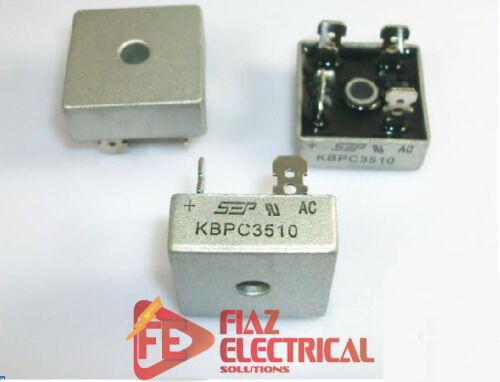
Bridge Rectifier KBPC3510 in Pakistan Everything You Need to Know
A bridge rectifier is an essential component in electronic circuits that converts alternating current (AC) into direct current (DC). It is widely used in various applications, including power supplies, motor drives, and battery chargers. In this comprehensive guide, we will delve into the details of the Bridge Rectifier KBPC3510 in Pakistan, its features, working principle, applications, and more. If you are based in Pakistan and looking for a reliable bridge rectifier, the KBPC3510 might be the perfect choice for your electronic projects.
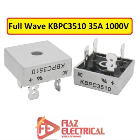
What is the KBPC3510 bridge rectifier?
The KBPC3510 is a bridge rectifier that belongs to the KBPC series. It is designed for high current, high voltage applications and can handle a maximum current of 35A and a maximum voltage of 1000V. The KBPC3510 is a single-phase, full-wave rectifier with four diodes connected in a bridge configuration. This configuration ensures that the output waveform is a full-wave rectified signal with minimal ripple. The KBPC3510 is widely used in power supplies, battery chargers, and other applications that require a reliable and efficient rectification process.
Features and specifications of the KBPC3510 bridge rectifier
The Bridge Rectifier KBPC3510 offers a range of features and specifications that make it a versatile component for electronic circuits. Some of the key features of the KBPC3510 include:
High Current and Voltage Rating: With a maximum current rating of 35A and maximum voltage rating of 1000V, the KBPC3510 can handle demanding applications with ease.
Low Forward Voltage Drop: The KBPC3510 has a low forward voltage drop, which ensures efficient power conversion and reduces power losses in the circuit.
Compact Design: The KBPC3510 is designed in a compact package, allowing for easy integration into various electronic projects.
High Surge Current Capability: The KBPC3510 is capable of handling high surge currents, making it suitable for applications with fluctuating loads.
Thermal Resistance: The KBPC3510 has a low thermal resistance, ensuring efficient heat dissipation and reliable operation even under high load conditions.
Understanding the working principle of the KBPC3510 bridge rectifier
The Bridge Rectifier KBPC3510 follows the working principle of a full-wave rectifier. During the positive half-cycle of the input AC waveform, diodes D1 and D3 conduct current, while diodes D2 and D4 are reverse-biased and do not conduct. This allows the positive half-cycle of the AC waveform to appear across the load resistor, resulting in a positive half-cycle of the output waveform.
During the negative half-cycle of the input AC waveform, diodes D2 and D4 conduct current, while diodes D1 and D3 are reverse-biased. This allows the negative half-cycle of the AC waveform to appear across the load resistor, resulting in a negative half-cycle of the output waveform. As a result, the Bridge Rectifier KBPC3510 produces a full-wave rectified output waveform with minimal ripple.
Applications of the KBPC3510 bridge rectifier in Pakistan
The Bridge Rectifier KBPC3510 finds wide applications in various industries and electronic projects in Pakistan. Some of the key applications of the KBPC3510 in Pakistan include:
Power Supplies: The KBPC3510 is commonly used in power supply circuits to convert AC voltage into DC voltage. It ensures a stable and reliable power source for electronic devices.
Battery Chargers: The KBPC3510 is used in battery charger circuits to convert AC power into DC power for charging batteries. It provides efficient and controlled charging for different types of batteries.
Motor Drives: The KBPC3510 is utilized in motor drive circuits to convert AC power into DC power for controlling the speed and direction of motors. It enables precise control and efficient operation of motors in various industrial applications.
Welding Equipment: The KBPC3510 is employed in welding equipment to convert AC power into DC power for welding operations. It ensures a stable and consistent power supply for high-quality welding.
How to choose the right Bridge Rectifier KBPC3510 for your needs
Selecting the right Bridge Rectifier KBPC3510 in Pakistan for your specific needs is crucial to ensure optimal performance and reliability. Here are some factors to consider when choosing the right KBPC3510 bridge rectifier:
Current and Voltage Requirements: Determine the maximum current and voltage requirements of your application to ensure the KBPC3510 can handle the load. It is important to choose a bridge rectifier with a current and voltage rating higher than your application's requirements to avoid overloading.
Package Type: Consider the package type of the KBPC3510 that suits your specific application. The KBPC3510 is available in various package types, such as through-hole and surface mount, allowing you to choose the one that best fits your circuit design.
Temperature Range: Evaluate the operating temperature range of your application and choose a KBPC3510 bridge rectifier that can withstand the temperature variations.
Manufacturer Reputation: Opt for a reputable manufacturer when purchasing the KBPC3510 bridge rectifier. A reliable manufacturer will ensure the highest quality and performance standards, providing you with a durable and long-lasting component.
Final thoughts on the KBPC3510 bridge rectifier in Pakistan
The Bridge Rectifier KBPC3510 is a versatile and reliable component for various electronic applications in Pakistan. Its high current and voltage ratings, low forward voltage drop, and compact design make it an excellent choice for power supplies, battery chargers, motor drives, and more. By understanding the working principle, applications, and selection criteria of the KBPC3510, you can make an informed decision when integrating it into your electronic projects. Remember to purchase the KBPC3510 from reputable suppliers and follow proper troubleshooting techniques in case of any issues. With the Bridge Rectifier KBPC3510 in Pakistan, you can ensure efficient and stable power conversion for your electronic circuits in Pakistan.

1 note
·
View note
Text
Safe and Reliable: The Advantages of Sealed Lead Acid Batteries for Home Backup Power
Lead Acid Battery
Introduction
Lead acid batteries are a type of rechargeable battery that have been widely used for several decades. These batteries are known for their reliability and durability, making them suitable for various applications ranging from automobiles to backup power systems. In this article, we will explore the key aspects of lead acid batteries, including their types, working principle, advantages, disadvantages, and maintenance tips.
Understanding Lead Acid Batteries
Lead acid batteries are a type of electrochemical storage device that converts chemical energy into electrical energy through reversible reactions. These batteries consist of two lead plates immersed in a sulfuric acid electrolyte. The plates are typically made of lead (Pb) and lead dioxide (PbO2), while the electrolyte is a diluted solution of sulfuric acid (H2SO4).
Types of Lead Acid Batteries
Lead acid batteries come in various types, each designed for specific applications. The most common types include:
Flooded Lead Acid Batteries: These are the traditional lead acid batteries with liquid electrolyte. They require regular maintenance to check the electrolyte level and may emit gas during charging.
Sealed Lead Acid Batteries: Sealed lead acid batteries, also known as valve-regulated lead acid (VRLA) batteries, are maintenance-free. They utilize a valve mechanism to control gas release, making them safer and suitable for applications where maintenance is difficult.
Gel Batteries: Gel batteries are a type of VRLA battery that use a gel electrolyte, which immobilizes the sulfuric acid. This design offers improved safety, longer cycle life, and better resistance to vibration.
Working Principle of Lead Acid Batteries
Lead acid batteries operate based on a chemical reaction that occurs between the lead plates and the electrolyte. During discharge, the lead (Pb) plate combines with sulfuric acid (H2SO4) to form lead sulfate (PbSO4), releasing electrons. When the battery is charged, the lead sulfate is converted back into lead and lead dioxide.
Advantages and Disadvantages of Lead Acid Batteries
Lead acid batteries offer several advantages, such as:
Relatively low cost compared to other battery technologies.
High surge current capability, making them suitable for applications that require a sudden burst of power.
Wide availability and established infrastructure for recycling.
However, lead acid batteries also have some disadvantages, including:
Relatively low energy density compared to newer battery technologies.
Limited depth of discharge and shorter cycle life compared to some other types of batteries.
Environmental concerns due to the presence of lead and sulfuric acid, requiring proper recycling and disposal procedures.
Maintenance and Safety Tips for Lead Acid Batteries
To ensure the longevity and optimal performance of lead acid batteries, it's essential to follow some maintenance and safety tips:
Regular Inspection: Check the battery terminals, cables, and overall condition of the battery regularly.
Keep the Battery Clean: Remove any dirt or corrosion from the terminals and clean them with a mixture of baking soda and water.
Proper Charging: Follow the manufacturer's recommendations for charging voltage and current to avoid overcharging or undercharging the battery.
Avoid Deep Discharge: Try to avoid fully discharging the battery, as it can lead to sulfation and reduce the battery's capacity.
Safety Precautions: When handling lead acid batteries, always wear protective gloves, goggles, and clothing to prevent contact with sulfuric acid. Follow proper recycling procedures to dispose of old batteries.
Conclusion
Lead acid batteries have been a reliable and cost-effective energy storage solution for many applications. Their ability to deliver high surge currents and established recycling infrastructure makes them a popular choice in various industries. However, advancements in battery technology continue to offer alternatives with higher energy density and longer cycle life. Understanding the advantages, disadvantages, and maintenance tips of lead acid batteries can help users make informed decisions about their energy storage needs.
FAQs
How long do lead acid batteries last? Lead acid battery lifespan depends on several factors, including usage, maintenance, and operating conditions. Generally, well-maintained lead acid batteries can last anywhere from 3 to 5 years.
Can lead acid batteries be recycled? Yes, lead acid batteries are highly recyclable. The lead and other materials used in these batteries can be reclaimed and used to manufacture new batteries.
Are lead acid batteries suitable for solar power systems? Lead acid batteries are commonly used in solar power systems due to their ability to handle high surge currents and relatively low cost compared to other battery technologies.
What is the recommended charging voltage for lead acid batteries? The recommended charging voltage for lead acid batteries is typically around 2.4 to 2.45 volts per cell, or approximately 14.4 to 14.7 volts for a 12-volt battery.
Can lead acid batteries leak acid? Yes, if a lead acid battery is damaged or improperly maintained, it can leak sulfuric acid. It is important to handle and store lead acid batteries properly to avoid any acid leakage.
0 notes
Text
https://www.futureelectronics.com/c/semiconductors/discretes--diodes--ultrafast-rectifiers/products
Ultrafast rectifiers can directly reduce switching loss and improve overall power efficiency due to a good combination between reverse recovery time and forward voltage. Some features and benefits include high reverse voltage surge capability, high thermal cycling performance, low thermal resistance, and very low on-state loss.
#Diodes#Ultrafast Rectifiers#ES1D#Surge#Vishay#US1J-E3/61T#Diodes Ultrafast Rectifiers#Single Ultra Fast Rectifier#high reverse voltage surge capability#Super Fast Rectifier#Utrafast rectifiers minimizes power#power supplies
1 note
·
View note
Link
Ultrafast rectifiers can directly reduce switching loss and improve overall power efficiency due to a good combination between reverse recovery time and forward voltage. Some features and benefits include high reverse voltage surge capability, high thermal cycling performance, low thermal resistance and very low on-state loss.
1 note
·
View note
Text
Southwire Surge Guard Portable 30-Amp 120-Volt Wireless Communication-Capable Surge Protector
Southwire Surge Guard Portable 30-Amp 120-Volt Wireless Communication-Capable Surge Protector
The Surge Guard 34931 provides total electrical protection for your 30-amp RV, including protection against wiring issues; reverse polarity, open neutral and open ground. Also protects against low/high voltage, low/high frequency and elevated ground line current. Ten-second start-up sequence and 128 second fault delay sequence protect compressor motors against damage. Works with Surge Guard…

View On WordPress
0 notes
Link
0 notes
Photo

MITSUBISHI PS11034-Y1 Https://www.slw-ele.com; Email: [email protected]
#PS11034-Y1 Mitsubishi PS11034-Y1 New PS11034-Y1 FLAT-base TYPE INSULATED TYPE 450V-500V/15A-30A , PS11034-Y1 pictures, PS11034-Y1 price, #PS11034-Y1 supplier ------------------------------------------------------------------- Email: [email protected]
https://www.slw-ele.com/ps11034-y1.html
-------------------------------------------------------------------
INTEGRATED FUNCTIONS AND FEATURES
• Converter bridge for 3 phase AC-to-DC power conversion.
• 3 phase IGBT inverter bridge configured by the latest 3rd.
generation IGBT and Diode technology.
• Inverter output current capability IO (Note 1):
(Note 1) : The inverter output current is assumed to be sinusoidal and the peak current value of each of the above loading cases is defined as : IOP = IO × √2, TC
INTEGRATED DRIVE, PROTECTION AND SYSTEM CONTROL FUNCTIONS:
• P-Side IGBTs : Drive circuit, high-level-shift circuit, bootstrap circuit supply scheme for Single Control-Power-Source drive, and under voltage (UV) protection.
• N-Side IGBTs : Drive circuit, DC-Link current sense and Amplifier circuits for overcurrent protection, control-supply under-voltage
protection (UV), and fault output (FO) signaling circuit.
• Fault Output : N-side IGBT short circuit (SC), over-current (OC), and control supply under-voltage (UV).
• Inverter analog Current Sense : N-Side IGBT DC-Link Current Sense.
• Input Interface : 5V CMOS/TTL compatible, Schmitt Trigger input, and Arm-Shoot-Through interlock protective function.
Supply voltage VCC 450V
Supply voltage (surge) VCC(surge) 500V
Each IGBT collector current ±Ic(±Icp) ±15 (±30) A
Repetitive peak reverse voltage VRRM 800V
Recommended AC input voltage Ea 220 Vrms
DC output current IO 15A
Surge (non-repetitive) forward current IFSM 150A
Supply voltage VD, VDB –0.5 ~ 20V
Input signal voltage VCIN –0.5 ~ +7.5 V
Fault output current IFO 15mA
PS11034-Y1 FLAT-base TYPE INSULATED TYPE 450V-500V/15A-30A
Shunlongwei Inspected Every PS11034-Y1 Before Ship, All PS11034-Y1 with 6 months warranty.
0 notes
Text
Global Power Electronics Market
Global Power Electronics Market Size, Share, Growth, Industry Trends and Forecast 2020-2030
The global power electronics market size was accounted at USD 24.5 billion in 2020, and is expected to reach USD 40.6 billion by 2030, registering a CAGR of 5.2%.Power electronics is an area that includes the study, analysis, and designing of various circuits that are capable of controlling and converting electrical energy from one form to another with the help of semiconductor devices. It helps in power management in order to enhance energy conservation in numerous uses such as industrial systems, electric vehicles, and consumer electronics. Power electronics devices have certain advantages including optimum forward and reverse backing capabilities, simplified circuits, and compact designs. Furthermore, other applications of power electronics devices include connection of renewable energy resources to power grids, transportation in electric locomotives, motor drives and illumination. The major use of power electronics devices is heat sinking as well as soft starting of equipment deploying power electronics devices. The various power electronics devices include insulated-gate bipolar transistor (IGBT), power metal oxide semiconductor field-effect transistor (MOSFET), diodes, thyristors, and silicon controlled rectifiers. The global power electronics market size was accounted at USD 24.5 billion in 2020, and is expected to reach USD 40.6 billion by 2030, registering a CAGR of 5.2%.
Download Sample Copy of the Report to understand the structure of the complete report (Including Full TOC, Table & Figures) @ https://www.decisionforesight.com/request-sample/DFS020281
Market Dynamics and Factors:
Rapid growth in the use of renewable energy, increase in the adoption of electric vehicles, and the surge in industries like automotive, industrial, consumer electronics, and ICT are the major factors driving the market across the globe. Additionally, the rising focus on enhancing the power infrastructure and the growing trend of energy harvesting technologies is also augmenting the market growth of power electronic during the forecast period. However, current leakage at high temperatures and high infrastructure deployment cost are hampering the market growth of power electronics devices. Furthermore, proactive government initiatives to establish high voltage direct current (HVDC) and smart grid utilizing power devices for power conversation are expected to provide lucrative opportunities for the market to grow in the coming future. The increasing demand for HVDC grids in countries like China and India and the adoption of Greenfield projects for generating energy from renewable sources are anticipated to further drive the growth of the power electronics market.
Market Segmentation:
Global Power Electronics Market – By Material
Silicon
Sapphire
Silicon Carbide
Gallium Nitride
Others
Global Power Electronics Market – By Device Type
Power IC
Power Module
Power Discrete
Global Power Electronics Market – By Applications
Power
ICT
Consumer Electronic
Industrial
Automotive
Aerospace & Defence
Others
Global Power Electronics Market – By Geography
North America
U.S.
Canada
Mexico
Europe
U.K.
France
Germany
Italy
Rest of Europe
Asia-Pacific
Japan
China
India
Australia
Rest of Asia Pacific
ROW
Latin America
Middle East
Africa
New Business Strategies, Challenges & Policies are mentioned in Table of Content, Request TOC at @ https://www.decisionforesight.com/toc-request/DFS020281
Geographic Analysis:
Asia Pacific is expected to dominate the global power electronics market in terms of market share during the forecast period followed by North America. The growth of the market in APAC is mainly attributed to technological advancements and increased focus towards the use of renewable energy sources across various industrial verticals across the region. For instance, in 2016, the government of India announced the construction of solar power projects with 4,000 MW worth capacity under the National Solar Mission. This was mainly due to the government’s interest in providing low cost renewable power to the rural and underserved population. Moreover, the rise of the consumer electronics, ICT, automotive, and industrial sector in various APAC countries like China, India, Japan, and South Korea has also contributed significantly to the market growth of the power electronics devices in the region. Power electronics plays a crucial role in electric vehicles in speed control at high voltages and enhancing efficiency. For instance, the U.S. has the largest consumer base of electric cars, because of strict emission rules in the region. In 2015, about 400,000 electric cars were in stock in the nation. This is a major factor attributing to the market growth of power electronics in the North American region.
Competitive Scenario:
The key players operating in the global power electronics industry are –
Texas Instruments, Qualcomm Inc., Mitsubishi Electric Corp., Toshiba, Hitachi, Fuji Electric, Renesas Electronic Corporation, ON Semiconductor, STMicroelectronics, Microsemi Corporation, and ABB Ltd.
Connect to Analyst @ https://www.decisionforesight.com/speak-analyst/DFS020281
How will this Market Intelligence Report Benefit You?
The report offers statistical data in terms of value (US$) as well as Volume (units) till 2030.
Exclusive insight into the key trends affecting the Global Power Electronics industry, although key threats, opportunities and disruptive technologies that could shape the Global Power Electronics Market supply and demand.
The report tracks the leading market players that will shape and impact the Global Power Electronics Market most.
The data analysis present in the Global Power Electronics Market report is based on the combination of both primary and secondary resources.
The report helps you to understand the real effects of key market drivers or retainers on Global Power Electronics Market business.
The 2021 Annual Global Power Electronics Market offers:
100+ charts exploring and analysing the Global Power Electronics Market from critical angles including retail forecasts, consumer demand, production and more
15+ profiles of top producing states, with highlights of market conditions and retail trends
Regulatory outlook, best practices, and future considerations for manufacturers and industry players seeking to meet consumer demand
Benchmark wholesale prices, market position, plus prices for raw materials involved in Global Power Electronics Market type
Buy This Premium Research Report@ https://www.decisionforesight.com/checkout/DFS020281
About Us:
Decision Foresight is a market research organization known for its reliable and genuine content, market estimation and the best analysis which is designed to deliver state-of-the-art quality syndicate reports to our customers. Apart from syndicate reports, you will find the best market insights, strategies that will help in taking better business decisions on subjects that may require you to develop and grow your business-like health, science, technology and many more. At Decision Foresight, we truly believe in disseminating the right piece of knowledge to a large section of the audience and cover the in-depth insights of market leaders across various verticals and horizontals.
Contact:
Email: [email protected]
For Latest Update Follow Us:
https://www.facebook.com/Decision-Foresight-110793387201935
https://twitter.com/DecisionFs
https://www.linkedin.com/company/decision-foresight/
0 notes
Text
The Mysterious Case of the Missing 250-Ton Chinese Power Transformer
In May, the Trump administration seized a 250-ton, $3 million Chinese high-voltage transformer that was on its way to Colorado. It was taken to Sandia National Labs in New Mexico for reasons unknown. What happened to it still remains a mystery.
On May 1, the Trump Administration issued a surprise Executive Order (EO), “Securing the United States Bulk Power System.” The directive aims to keep critical equipment supplied by foreign adversaries out of the nation’s power grid due to supposed supply chain security threats. It requires the Secretary of Energy to work with other agencies in identifying the specific equipment from adversarial suppliers, particularly Chinese suppliers, that the government should bar from the bulk-power system.
The Department of Energy (DOE) has to issue relevant rules on the matter within 150 days, or by September 28. Shortly after the EO’s release came the surprising revelation that a federally owned utility managed by DOE, the Western Area Power Administration (WAPA), hijacked a nearly $3 million Chinese-manufactured transformer initially intended for one of its substations in Colorado. WAPA instead diverted it to one of DOE’s national laboratories, Sandia National Labs, in New Mexico.
The manufacturer of the high-voltage 500,000-pound transformer was Chinese company JiangSu HuaPeng Transformer Co., Ltd., or JSHP, which shipped the transformer from Shanghai to the Port of Houston in August 2019.JSHP’s North American representative Jim Cai told Motherboard his company planned to spend a couple of hundred thousand dollars to transport the high-grade steel using a particular kind of railroad car to WAPA’s Ault substation in Colorado, where JSHP would then install it. Like all electric substations, the Ault facility’s main purpose is to “step down” high-voltage electricity, typically above 1,000 volts, to lower, more manageable levels that can be distributed safely to homes and businesses.
Before the ship docked in Texas, WAPA told JSHP to cancel its plans to transport and install the transformer and to forget about selling a warranty on the equipment, which is almost always mandatory for highly specialized, expensive electrical system equipment. The utility then transported the transformer itself to Sandia. Since then, WAPA and DOE have been silent on this odd development, which has sparked confusion and concerns among utilities and industrial control system (ICS) security specialists.
Motherboard has spent the past two months delving into possible reasons why WAPA hijacked its own transformer and why DOE—and practically everybody else—isn’t talking about it. We also investigated whether DOE asked another company to build a replacement transformer for the Ault substation. Here’s what we discovered regarding what industrial control security specialist Dale Peterson has dubbed “transformergate.”

Another JSHP transformer, at a Shanghai port
Did DOE Suspect the JSHP Transformer Contained Hidden, Destructive Backdoor Weapons?
One industrial control security expert published a controversial piece in May that said the discovery of a hidden backdoor capable of causing a catastrophic-level event in a high-voltage transformer supplied by a Chinese company is what spurred the EO. Although most ICS specialists ignored this unverified assertion, some prominent ICS security experts were outraged when it surfaced in news reports connected to the missing transformer. They saw undocumented fear-mongering and sensationalism by an unreliable source, which often occurs when it comes to alleged threats to the electric grid.
In early July, Robert M. Lee, founder and CEO of top ICS security consulting firm Dragos, and an adviser to DOE, issued a 20-page paper along with colleagues from the information security training organization SANS Institute dismantling the validity of the backdoor claims. He assigned them a credibility score of zero because the individual making those claims offers no substantiating information to back them up, nor is he in any position to have first-hand knowledge of them.
Moreover, no one has produced any evidence to back up those kinds of claims, the paper’s authors report. “The position of the SANS ICS team is that currently there is not enough information provided to validate the claims nor is there actionable steps to take for defenders who may wish to address the claims regardless of credibility or accuracy.”
JSHP’s Cai denies the presence of a backdoor in his company’s equipment but says he believes that DOE suspects China of booby-trapping its power grid gear. Cai points to early 2019 press reports in which DOE officials talk about the risks of Chinese equipment in electric facilities.
The Trump administration has launched a number of actions to bar Chinese technology in the U.S. communications infrastructure, including an executive order primarily aimed at telecom tech giant Huawei. In May, the Commerce Department made it difficult for Huawei to acquire U.S.-made semiconductors. In June, the Federal Communications Commission designated Huawei and its peer ZTE as supply chain threats and ordered the mostly rural telcos to replace that kit as soon as possible. Finally, the administration’s latest Chinese target is video app TikTok, which has presumably calmed supply chain fears by working out a “trusted tech” partnership of sorts with Silicon Valley giant Oracle.
Based on phone calls Cai says he received in early 2019 from industry analysts and consultants, he thinks that DOE suspects one of his company’s transformers installed at the Bayonne (NJ) Energy Center, a generating facility now owned by Scottish company Ethos Energy, was responsible for the so-called “blue sky” incident in New York in late-December 2018. In that widely reported “arcing” incident, an explosion at ConEd’s Astoria substation caused the New York skyline to shine bright blue for a brief period.
Although the technical details are intricate, utility engineers say that it’s virtually impossible for a generating plant’s transformer, in this case the high-voltage transformer supplied by JSHP in Bayonne, to cause a downstream incident in a substation transformer receiving electricity, such as the device in Astoria.
The only way that could happen, according to Richard Shiflett, electrical engineer and senior security consultant at ICS consulting firm Archer Security, is for the Bayonne transformer to send an abnormal surge of electricity to Astoria, and even then, the odds are vanishingly small anything would happen. “It’s unlikely that voltage going up or down by virtue of that output would cause this kind of event,” he told Motherboard. “There would have to be other kinds of contributing factors with that tap change to result in a phase-to-phase or phase-to-ground fault [that occurred in the Blue Sky] incident.”

Other JSHP units.
Patrick Miller, head of Archer Security and founder of energy industry consortium EnergySec, is blunter. “The requirements to get a transformer to do that are insanely challenging from a physics perspective. It’s profoundly improbable. Especially when there are so many other ways to get a much higher reach for an attack. It doesn’t fit China’s mentality. They’re not a full-frontal attack kind of country.”
ConEd, which never publicly explained the blue-sky incident, sent Motherboard a statement saying, “on December 27, 2018, an electrical fault on a section of 138-kV equipment in an Astoria substation caused a transmission disturbance. The equipment that malfunctioned was associated with voltage monitoring within the substation. We have concluded our review and are not aware of any further investigation into the matter.”
Is DOE Reverse-Engineering the Transformer?
The U.S. once was the chief supplier of high-voltage electrical transformers, but today few, if any, high-voltage transformers are made by American companies on U.S. soil. One theory is that DOE transported the JSHP transformer to Sandia to break it down and reverse engineer it. The goal of this breakdown would be to help the U.S. decipher manufacturing methods that may help the country take back some market share.
Most experts say that’s not the style of U.S. industrial efforts, even as China routinely engages in reverse engineering for economic espionage purposes. Joe Slowik, Principal Adversary Hunter at Dragos, wrote in a paper regarding why DOE hijacked its transformer, “one item that can likely be ruled out, despite the evisceration of the US transformer manufacturing market, is potential economic espionage. While occasional stories emerge of US government resources used to conduct economic espionage, the sourcing is poor and typically when taking place such operations are directly related to national security items and not for the benefit of private companies.”
“We absolutely do not do that,” Bryson Bort, CEO of industrial security firm Scythe and co-founder of the hacking conference DEF CON’s ICS Village, told Motherboard. “This is kind of what makes us different from [China]. The U.S. government does not do corporate espionage, which is essentially what the accusation is here.”
Did DOE Want the Chinese Equipment for an Experimental Transformer Program?
One theory floated by JSHP’s Jim Cai is that DOE might have needed the transformer to boost its hybrid transformer development program currently underway at Sandia Labs. That program seeks to merge transformer technologies to improve performance and reliability.
Most energy experts say that’s not possible. “The thing about transformers is that most of the time they’re custom-built,” Archer’s Miller says. “They’re not like Legos where you can just pop them in, and they’ll work. They’re a custom-made object. Otherwise, we could just go down to Home Depot and go and buy a transformer.”
Where Did WAPA Find a Replacement Transformer?
Whatever may have happened to the JSHP transformer after it arrived in the U.S., WAPA initially and ostensibly ordered it because it needed the equipment to help run its Ault substation in Colorado. According to public documents related to the DOE-JSHP contract, the utility ordered the transformer on September 26, 2017, 15 months before the Blue Sky incident and far ahead of when the Trump administration’s concerns over China’s supply chain threats reached their apex in the 2020 Executive Order.
According to publicly available documents, about a month after WAPA transported the JSHP transformer to Sandia, the utility issued a $6.1 million sole-source contract to an 8-A firm in the San Antonio, TX area called Taurean General Services. That contract, dated September 25, 2019, required delivery of a transformer for the Ault substation, along with a transformer for another WAPA facility called North Cody and equipment called a shunt reactor for WAPA’s Badwater facility. The location of this contract performance in public records is listed as “Croatia.”
Jeff Jaime, the CEO, and Founder of Taurean, who is a former Air Force IT security specialist who primarily fulfills orders for the military, told Motherboard his job was simply to find the transformers and shunt reactor for WAPA. He’s not aware of any of the background related to the JSHP contract. “In a high level, we receive general requirements, and we find manufacturers of the products that the government is looking for with very specific technical specs,” he says.
When asked whether he purchased the transformers and shunt reactor from a manufacturer in Croatia, he said he would have to get WAPA’s permission to tell Motherboard. When informed that “Croatia” is written on documents in the public record, he said, “if it’s public record, you don’t have to ask me.”
Representatives of KonKar, the only manufacturer in Croatia capable of producing a high-voltage transformer, did not respond to requests for comment.
How Can DOE Keep the Whereabouts and Status of a 250-Ton Transformer Secret?
Motherboard has asked WAPA in various forms about the fate of the JSHP transformer and its possible replacement. WAPA CEO Mark Gabriel repeatedly told Motherboard in an interview that the information is “critical electric infrastructure information” or CEII. Effective as of May 30, 2020, CEII is a new designation for the DOE that exempts the department from making public information that, among other things, could be useful to someone planning an attack on critical infrastructure.
Although the Federal Energy Regulatory Commission (FERC), which, unlike DOE, is an independent regulatory agency, has long had CEII rules in place related to the bulk power grid, DOE’s CEII rules are currently being challenged in the courts by a coalition of public interest groups as being illegal and overly broad. The alliance challenging DOE’s rules includes the Union of Concerned Scientists, Public Citizen’s Energy Program, and Earthjustice. These critics say that DOE exceeds its statutory authority in a way that could allow it to designate almost any piece of information submitted to the Department as CEII.
The DOE’s challengers argue that there is a legitimate role for CEII designations in order to protect the U.S. electric grid. And they also stress that they are unfamiliar with the situation involving the Ault transformer. Still, they argue that DOE’s job is to follow FERC’s blueprints, which they believe are less political and better balanced when it comes to weighing critical infrastructure protection against the public’s right to know. “What DOE is supposed to be doing is following the regulations that FERC has established,” Cassandra McCrae, an associate attorney at environmental law non-profit organization Earthjustice, tells Motherboard.
Kim Smaczniak, Managing Attorney of the Clean Energy Program at Earthjustice, says, “FERC is very cognizant that there are important public uses for information. There are legitimate concerns about DOE under its rules that it is unlawfully setting forth here, whether it’s going to take the same kind of approach that FERC has.”
Even if too restrictive from a public interest perspective, the DOE’s CEII rules fit right in with the culture of the electric utility industry, which has long been press-shy about technical information. Many if not most utility engineers are required to sign NDAs.
Virtually no representative of a utility or DOE we contacted for this story would talk on the record, despite repeated requests. Ethos Energy, which owns the Bayonne facility, also did not respond to a request for comment. ICS security firm Dragos declined comment.
DOE’s silence on the fate of the transformer and its unexplained diversion to Sandia Labs has left the U.S. power industry puzzled, opening the door for a lot of theories but no answers. As of today, for all but a handful of people at DOE who presumably know what’s going on, the JSHP transformer is still missing in action.
The Mysterious Case of the Missing 250-Ton Chinese Power Transformer syndicated from https://triviaqaweb.wordpress.com/feed/
0 notes
Text
The Lighting Product EMC Problem and Testing Technology
LEDs and LED luminaires with high light efficiency, longer lifetime, better energy saving and environmental friendly advantages to achieve top position on the lighting industry, like indoor and outdoor lighting application. With the introduction of various national support policies, there appeared many LED lighting products manufacturer, but the quality of LED lighting products is not good well which influence the LED lighting product’s marketing promoting more or less. According to market quality checking, the failure rate of LED lighting product reach to 39%, most of failure products related with harmonic currents, surge impact, harassment voltage electromagnetic compatibility test items. Electromagnetic compatibility (EMC) is an important factor affecting the reliability of LED lighting products.
1. EMC Test Standards: There haven’t LED special standards focus on EMC test, the current practice is based on the field of LED lighting products, refer to the implementation of the relevant standards. Such as automotive LED lighting products should refer to CISPR25<Limits and test methods of protect vehicle receiver from radio disturbance characteristics>, ISO7637-2< Road vehicles – Transient conduction from conduction and coupling of electrical disturbances along supply lines> and ISO11452< EMI electromagnetic energy – Component test methods for road vehicles narrowband radiated> etc EMC standards, this article will not discuss them here. The point need discuss is general purpose LED lighting products (except automotive lighting, aircraft lighting, photocopiers and other special LED lighting equipment) EMC test standards, as shown in Table 1 below:

The Lighting Product EMC Problem and Testing Technology
2. EMC Test Item: LED lighting product’s EMC test item included EMI and MES. EMI mean electromagnetic interference, test LED lighting products may cause performance degradation or damage to generate electromagnetic disturbance of other things (including equipment, systems, people and animals and plants). EMS mean electromagnetic susceptibility( immunity test), test LED lighting product’s immunity ability for electromagnetic disturbances such as lightning, ESD static test and the fight against ringing waves immunity.

The Lighting Product EMC Problem and Testing Technology

The Lighting Product EMC Problem and Testing Technology
The table 2 list EMC test items of LED lighting products which inlcuded main test intem, main test equipment, test environmental. The following will focus on the EMI test, electrostatic discharge and surge test.2.1. EMI Test:EMI(Electromagnetic Interference) included conducted interference and radiated interference. Conducted interference refers to the signal coupling through a conductive medium (interference) on an electric power network to another network; Radiated interference is the source of interference to its signal coupling through space (interference) to another radio network. In high-speed PCB and system design, the high-frequency signal line, the integrated circuit pins, various types of connectors so may become a source of interference with the antenna radiation characteristics, capable of emitting electromagnetic waves and affect other systems or to other subsystems within the system normal operation. As we know, the test object for EMC is electronic and electric device, among them, lighting is an important part which should do the EMC test naturally. Like FCC from America and CE from European Union, both of them request EMC measurement of LED lighting device. When talk about electromagnetic disturbance, generally it indicates two disturbance sources, one is conductive interference, it means that the disturbance signal will affect the EUT by conducting medium or public power supply; according to FCC, the LED lighting should do the conductive interference test at the frequency of 0.15MHz to 30MHz; but according to CE, it requests to do the test at the frequency of 9KHz to 30MHz. The other is radio disturbance, it means the disturbance signal will pass to electric network or device by the way of space coupling; according to FCC, the LED lighting should do the radio disturbance test at the frequency of 30MHz to 1GHz; but according to CE, it requests to do the test at the frequency of 30KHz to 300MHz.
In the lighting industry, when testing EMI frequency range at 9KHz~30MHz, there have two ways: The first is use Antenna and EMI Receiver which according to CISPR15, EN55015 and GB17743. For the low-frequency magnetic fields equipment which may produced by lighting luminaries, it need to adopt the provisions of tricyclic CISPR16-1-4 low frequency magnetic field antenna measurement radiation harassment. This need use three Loop Antenna and EMI receiver working together to measure it, and the testing must operate at inside of shielded room. Note: the three loop antenna made X direction, Y direction and Z direction’s low frequency magnetic field component converted to RF signal, and supplied to a receiver via three channels of EMI coaxial switch; The second way is use LISN, the testing system include EMI Receiver, Artificial Network Power, LISN and software. Conduction disturbance test system for measuring normal working lighting and lighting equipment’s harassmen which produced by power port. LISN achieve isolation RF signal, sampling, impedance matching, and provide electricity for EUT channel, EMI receiver for RF signal measurements and finally analyzed by EMI testing software, processing and sentenced limit. The testing must operate at inside of shielded room.
At the meantime, the testing EMI frequency range at 9KHz-300MHz will be use CDN. The CISPR15,EN55015 and GB17743 standards are also mentioned another way to measuring lighting equipment’s radiation harassment electric. that’s CDN common-mode terminal voltage method. The CDN test method include EMI Receiver, CDN and Attenuator, the testing can operate at inside of shielded room.
Base on CISPR16, Lisun Group developed two EMI test systems. According to the standards for traditional Lightings and new LED lightings, the frequency scanning range is different. The scanning frequency for EMI-9KB is 9 KHz to 300MHz, which is applied to LED and traditional lighting test; the scanning frequency for EMI-9KA is 9 KHz to 30MHz, which is applied to traditional lighting test. Both of them input three data to judge if the EUT can pass the test or not, that is PK, QP and AV. And user is freely to setup the standards (like GB17743, FCC, EN55015, GB4343) directly in the software.
2.2. Electrostatic Discharge Test:
LED is semiconductor device, under LED manufacturing, assembly, transportation, storage, production of equipment, materials and the operator all of these factors can bring static losses of LED which caused leakage current increases, the light fades increase, or even “dead lights” phenomenon. Electrostatic discharge will caused influence and damage for reverse leakage current, forward I-V characteristic and luminous flux of LED product. Electrostatic discharge is one of the important factors affecting the LED and LED lighting product reliability.
LED chip is key part of LED lighting product. For LED electrostatic discharge immunity testing should follow the relevant international standards such as the American National Standard ANSI / ESD STM5.1, ANSI / ESD STM5.2, the IEC(International Electrotechnical Commission) standard electronic JESD22-A114D, JESD22-A115-A, the US military Party standard MIL-STD-883 and so on. Lisun Electronic Shanghai office R & D designed and developed ESD61000-2 Electrostatic Discharge Simulator which is designed according to LEDs static-sensitive level and characteristics, it applied with Machine Model (MM) and Human Body Model (HBM) electrostatic discharge test, electrostatic discharge voltage maximum up 30KV; LED voltage and current measure accuracy can reach to 0.2%; LED forward voltage resolution 1mV; reverse leakage current resolution 0.01μA. For LED lighting product, it electrostatic discharge immunity test shall be in accordance with GB / T 17626.2 / IEC61000-4-2 conducted. Contact discharge is the preferred test method for each metal parts (excluding terminals) accessible on the cabinet LED lighting products for 20 consecutive discharge, polarity 10 times each. It can be use air contact discharge test if can’t use contact discharge test. Indirect discharges shall be applied to the horizontal or vertical coupling board in accordance with GB / T17626.2 of. To ensure consistency and repeatability of test results, electrostatic discharge test specification must be 7 chapters are arranged according to GB / T17626.2. ESD61000-2 ESD simulator calibration data are as follows:
Calibration Data:

The Lighting Product EMC Problem and Testing Technology
2.3. Surge Test:
Lightning is very common climate phenomenon, according to statistics, there are over 40,000 of the world thunderstorm centers, eight million lightning strikes a day, which means lightning about 100 times every second occurrence. Lightning struck near the ground or nearby objects which caused strong electromagnetic field around it, then induces a high voltage and high current on the line. On the other hand, the surge in the power system is a very common phenomenon. As the main power supply switch, short-circuit and arc fault or ground network grounding systems and so on.
LED lighting products, especially for outdoor lighting products if without pay attention to lightning surge protection, it will seriously affect product reliability. A large area of LED lights in case of damage after thunderstorms common; According to quality supervision that there around have 60% LED lighting products can not meet lightning surges requirement. To assess the impact of LED lighting products, surge immunity performance shall be in accordance with IEC / EN61000-4-5 and GB / T 17625.5 requirements were surges testing. Test principle shown in Figure 5, the coupling network of common mode and differential mode test is different, differential mode test mean line – line test, the coupling capacitance is 18μF, it used to simulate the actual capacitance between the clouds and the earth; Common mode test mean line test – to earth test, the coupled network consist of capacitor and resistor network in series, the capacitor is 9μF and resistance is 10Ω.

The Lighting Product EMC Problem and Testing Technology
Lisun Electronic Shanghai office R & D designed and devolped
SG61000-5 Surge Generator
which applied big LCD touch screen technology and it has built-in Windows CE operate syste. This surge generator can test maximum 12KV voltage output, the user can set up common mode test or differential mode test by themselves. Moreover, this device can automatic record the EUT test parameters after finished test, these parameters can give designer some reference.
0 notes