#fiberglass antenna tube
Explore tagged Tumblr posts
Visit Tumblr Blog
Explore Tumblr blogs with no restrictions, modern design and the best experience.
Last Seen Tumblr Blogs


Fun Fact
Tumblr.com rank in the US is 25.
Text
Custom Fiberglass Poles Are Lightweight, Durable and Corrosion-Resistant

Fiberglass poles are lightweight, durable and corrosion-resistant. They are used for a wide variety of applications. They can be used for poles, flagpoles, cable support rods, antenna poles and more. They are also commonly used in food processing equipment, duct rods and in the construction of retaining wall pins.
Rods made from fiberglass are manufactured by a process called pultrusion. This process uses molten glass and thermoplastic resin to create long threads that are shaped into the shape of a rod. The rods are then cured to make them strong and rigid.
The process produces very thin rods, typically 1/8” to 1/4” in diameter. They are usually round in shape. The rods are then drilled or carved to length by cutting the rod into sections.
These pultruded fiberglass rods are often used for a wide variety of fishing purposes including for catching bass, pike, catfish and other fish that require the strength of a rod to withstand the pressure of a fight. They are also very useful for tying rigs and rigging up bait, including tube and worm rigs.
They are available in a variety of colors and are made to withstand the harshest conditions. They are rust and moisture resistant, and can stand up to temperatures as low as -65 degrees Fahrenheit and as high as 110 degrees. They can withstand wind, water, insects and salt.
Fishing with a frp poles is an enjoyable experience, and it can be a great way to get the most out of your time on the water. They are relatively easy to transport and can be very inexpensive, especially compared to other types of rods like graphite or bamboo.
If you are looking for a fiberglass rod, you should choose one that is sensitive and has an action that you like. This will help you improve accuracy and have a more enjoyable time on the water.
A quality fiberglass rod is very durable and has a slow action that makes it ideal for tying rigs and catching small fish. The slower action helps the rod to flex more easily when you tangle with a fish. It can also be very helpful when tangling with a big fish because the added drag can help firmly set your hook and protect your rod from snapping.
You can also use a fiberglass rod for tying baits and rigging up lures. The smooth feel of a fiberglass rod makes it easier to tie on baits and can increase the effectiveness of your tying by reducing the chance of kinks in the line.
A fiberglass rod is a great option for anglers of all skill levels. It is a durable, flexible, and affordable fishing rod that can withstand the rigors of a hard-fighting fish. It is also a good choice for those who are new to fishing and want a rod that will give them confidence when they catch their first fish.Check out this website at https://www.youtube.com/watch?v=Ha3XnGHm7Wk for more info about fiberglass.
0 notes
Photo

C&T RF Antennas Inc - Outdoor White color fiberglass antenna for wifi router 802.11 long distance Omni dipole Wifi 2.4Ghz antenna
#C&T RF Antennas Inc#fiberglass antenna#fiberglass antenna mast#fiberglass antenna tube#fiberglass antenna mount#fiberglass antenna cover#fiberglass antenna support#fiberglass antenna mast base#fiberglass antenna amazon#fiberglass vs aluminum antenna#tuning a fiberglass cb antenna#fiberglass boat antenna#fiberglass base antenna#fiberglass cb base antenna#uhf fiberglass base antenna#vhf fiberglass base antenna#best fiberglass antenna
0 notes
Text
Buat Sendiri Antena 40 Meter Band Dari Tubing Aluminium
Membuat sigma4 sebernarnya tidak ada bedanya dengan membuat antena J pole, hanya untuk memcari impendasinya untuk Jpole menggunakan trapshort, Sigma pun bisa saja dengan cara trapshort disini kita menggunakan gamma match (capasitor variable matching), untuk radial 50cm (1/4Lamda) 4bh, lingkaran 1m (1/2lamda), untuk radiator awal 7/8lamda ( 300/f x 7/8) x 95%, kira2 1.7m, jika menggunakan. Membuat sigma4 sebernarnya tidak ada bedanya dengan membuat antena J pole, hanya untuk memcari impendasinya untuk Jpole menggunakan trapshort, Sigma pun bisa saja dengan cara trapshort disini kita menggunakan gamma match (capasitor variable matching), untuk radial 50cm (1/4Lamda) 4bh, lingkaran 1m (1/2lamda), untuk radiator awal 7/8lamda ( 300/f x 7/8) x 95%, kira2 1.7m, jika menggunakan. Untuk antena 10 meter, elemen dapat dibuat dari tubing diameter ½ inch dan ¾ inch, untuk 20 meter dengan diameter ¼, ½ h, ¾ dan 1 inch. Mengenai diameter tubing dapat dicoba coba sendiri oleh rekan rekan amatir sehingga didapatkan performance yang cukup baik, mengingat tersedianya tubing aluminium di pasaran pada masingmasing tempat. #AntenaDuameterbandMurah #AntenaDuameteranRakitan #TutorialBahan:. 2 Batang kuningan Panjang 52 CM. Pipa PVC. Kabel RG 58 70 cm. Konektor dan Sambungan Leter I.
Buat Sendiri Antena 40 Meter Band Dari Tubing Aluminium 1
Buat Sendiri Antena 40 Meter Band Dari Tubing Aluminium Air
Buat Sendiri Antena 40 Meter Band Dari Tubing Aluminium 2
For the PACC contest I need (several) antennas for every band. Up to 40 meters it’s possible to make these antennas rotatable looking at the size of the antennas (and my backyard). After using verticals for 40 meter and last year a delta loop this year I choose to make a rotatable dipole. The small crank up tower against the barn makes this possible.
The antenna is made from 2 fishing poles on a fiberglass pole in the center.
The antenna is:
Easy to make
Cheap
No traps
Light in weight
An easy antenna project
Great for field day use and as ‘extra’ antenna at home for additional bands (or contests).

Needed materials are:
2 fishing rods (of better) as long as possible (up to 10 meter length)
1 meter center support pole (to slide the fishing poles over)
Mast to boom support
Some tyraps and/or electrical tape
Feed point insulator with 1:1 balun/choke
Some cheap wire as antenna wire
Some tools
Construction The center support is a 1 meter fiberglass tube bought on a flea market. These poles most often come in a package of 5 for 25 Euro and are former military masts. The center support could also be a small aluminum pipe but this is what I had in the barn. The mast to boom clamp will attach the center support pole to the mast (above the rotor if available).
(Picture center support needed with only center support pole)
The two fiberglass (fishing) rods do slide over both ends of the sturdy center fiberglass pole. The center pole is thickened on the end and almost at the center with electrical tape (on 4 places) in such a way that the fishing poles have a snug fit on the center pole. Not shown in the picture is a rope from one fishing pole to the other to prevent them from sliding of the center fiberglass pole.
The fishing poles should be as long as possible. A 40 meter dipole is around 10.10 meters per side. As the fishing poles I had lying around were 8.70 meters this is what I used. Most of the mechanical construction is now ready.
Wire length and support The length of the fishing rods is 8.70 meters and yes, too short. There are several solutions to this.
use a longer center tube and do not slide the fishing poles up to the mast to boom clamp. In my case a 3 meter center support pole would have given me around 10 meters (with 50 cm room for the fishing rods to slide over the center support).
Use coils. Not easy to make and how much windings do you need. This depends a lot on the fysical place along the antenna wire.
Use linear loading. Easy to make, just wire. You have to sort out how long the linear loading should be, where to start and where to end.
The linear loading solution is what I choose and made.

The antenna wire starts in the center from the balun and goes over the fishing pole to around 6 meters, then goes back about 2 meters and then back again to the end of the fishing rod. The length from the center of the antenna and the start of the linear loading should be as long as possible (4.1 meters in my case). The linear loading part is 2 meters long (between 4 and 6 meters on the fishing rod). There are 3 wires on the fishing pole between 4 and 6 meters. The end of the antenna is again a single wire from 6 to 8.7 meters (tip of antenna).
The wires are each one piece with a length of 13 meters and taped (or use tyraps) to the fishing pole. The picture below shows the linear loading at around 7 meters on the fishing pole.
The distance between the wires was in my case only a few centimeters as I taped the wire on the fishing pole (so around 2 cm). Of course you could make the distance wider by using small PVC supports like I used for the multiband vertical but I saw no need for it.
The picture below shows the complete linear loading wires (before taping is all up.)
Feed point and Balun In the center I used a center connector bought on a flea market. This was before I had my baluns ready. The center pin of the coax is attached to one end of the antenna and the shield to the other end of the antenna. When I used the antenna a choke balun of type W1JR which was attached direct to the connector of the antenna.
Adjusting When all is done the final check is if the antenna is in the 40 meter band. Wow, it was just below it (around 6.8 MHz). This was 2 meters above ground. Once is was on 11 meters in the small tower the resonance frequency went up to 6.95 MHz. The total bandwidth is very wide and even at 7.2 the SWR is way below 1 on 2.
The place of the linear loading on the fishing rod and length (and distance between the wires) will influence the resonance frequency. So pruning the length of the linear loading and the place on the fishing rod will take some time to get the antenna in resonance on 40 meters. In my case it was just luck that I was that close and really needed no pruning at all.

Buat Sendiri Antena 40 Meter Band Dari Tubing Aluminium 1

Using this technique using different lengths of fishing rods, different lengths of wire and different lengths (size)of linear loading will make is possible to use it on other bands as well.
Conclusion The antenna was easy to put together and took about 2 hours in total. Placing it in the small tower was easy as the antenna is very light in weight. It is wide however and some room is needed. The picture below gives a view of the antenna on top of the small tower. During the PACC contest the antenna worked well. The height of course could have been better but this is what I have.
Buat Sendiri Antena 40 Meter Band Dari Tubing Aluminium Air
Note: Above the rotary 40 meter linear loaded dipole is a N6RK receive loop (which works very well).
Buat Sendiri Antena 40 Meter Band Dari Tubing Aluminium 2
73’ Thomas PA1M 8 august 2012
0 notes
Text
Circuit boards: so important, but so undervalued
Circuit boards are literally the basis of electronic products and systems. They connect and "wire" dozens, hundreds, and even thousands of active and passive components with tiny islands and thin tracks, while also providing physical support, mounting tabs, connectivity options, and more. Printed circuit boards are often referred to as PCBs or PC boards and a few years ago the IPC, a major organization that sets standards (formerly the Institute for Interconnecting and Packaging Electronic Circuits), tried to call them 'printed wiring boards' or PWBs, but they never succeeded.
We don't need to tell our readers how important the role of printed circuit boards is and how versatile and versatile they are. But in many conversations they are casually seen as an insignificant, if essential, passive part, but that is a simplified misconception.
The interesting history of the circuit board
PCB board assembly have undergone an interesting development. When they were first used some 50 years ago, they were seen by many designers as a necessary evil. They replaced the use of point-to-point wiring and manual soldering, a technique that could no longer meet the demand for products such as color televisions, with their 100+ vacuum tubes. Nevertheless, a major TV retailer at the time prided themselves on the fact that their televisions were handcrafted by craftsmen, rather than by means of an anonymous printed circuit board. We all know what's left of that marketing story.
The first printed circuit boards were single-sided and made of phenol or bakelite, instead of our modern fiberglass-epoxy composite. The holes for the components and wires were punched instead of drilled and they were still hand soldered (Figure 1). The track width varied from 3 to 6 millimeters (mm).
Simple, one-sided 'through-hole' printed circuit boards like this one were made from phenol and were the first widely used versions of printed circuit boards.
The reliability of these youthful printed circuit boards was marginal due to coating delamination, tolerance issues and soldering inconsistencies. But as they say, failure was not an option, as using printed circuit boards was the only viable method to handle the large numbers of components, ICs, smaller components and more pins. In addition, they were able to provide surface mount components with sufficient support. The current circuit boards have been improved many times over in terms of performance and capabilities compared to those first circuit boards.
Interestingly, single-sided phenolic boards are still used in some consumer devices with almost all components. Wire jumpers inserted at the top allow a very inexpensive, single-sided card to be used
Figure 2: This 2010 microwave oven phenolic circuit board contains the power supply (low and high voltage), transformer, switch components, and much of the rest of the circuitry. Pay particular attention to the use of jumpers on the top that allow for a low-cost single-sided circuit board.
The multitasking precision of a printed circuit board
Despite the casual way we often talk about printed circuit boards, today's copies are very precisely designed precision parts. So much is expected of them, much more than just component carrier and connection platform. A number of tasks are:
They conduct current through the exposed layers if it is a simple two-sided printed circuit board.
In multi-layer maps, such as the commonly used four-layer printed circuit board, one inner layer provides power for one or more busbars and the other inner layer provides ground functions. If necessary, these layers are connected using conductive vias (short for 'vertical interconnect access' and written in lower case).
The copper around or near a hot component acts as a heat sink or as a thermal conductor to conduct heat away to a discrete drain.
The PCB copper can be configured as an RF transmission line, filter, isolator or circulator using stripline or microstrip topologies.
The printed circuit board can also be designed as an antenna, often in multi-band format, rather than a single band antenna.
Passive RF components, such as capacitors and coils, can also be constructed using suitable copper cartridges.
Accurately dimensioned tracks can act as low value (several milliohm) resistors to measure current through the IR drop across the track.
The copper can also serve as a protective ring around sensitive, low-level analog sensor inputs to op amps.
Also, the copper of the PCB can act as an EMC shield to prevent incoming RF from affecting the circuits and to attenuate emissions from the PCB.
The plug-in connector for both solid and flexible pins that terminate individual wires in a cable harness.
Read more Cable and Wire Harness Assembly
And if that were not enough, we can add a new role to the list: act as a socket for an IDC ribbon cable connector (insulation displacement connector) from Würth Elektronik . Instead of the standard IDC connectors, one male with pin contacts (pins) and another with female contacts, the Würth uses the PCB as a partner for the male IDC.
Note that this is not the first time wires have been connected directly to a circuit board. Individual solid or flexible pins have been pushed through metalized holes in a printed circuit board for years. But these pins cannot be removed without damaging the pin and the PCB, so they are a one-time use only. In contrast, Würth 's REDFIT IDC SKEDD connectors can be inserted and removed up to ten times at specified hole size and coating, up to 25 times at lower tolerances.
Image 3: Thanks to the REDFIT IDC SKEDD connectors from Würth, the IDC connector no longer needs a male (s) IDC and flat cable. This saves costs, simplifies the bill of materials and reduces the number of wire-connector transitions and thus potential problems.
What does the future of the everyday and underappreciated PCB look like? It seems that the widely used FR-4 epoxy glass substrate does not remain as dominant as it is today. The inherent characteristics of this technology does not meet designs to the stringent requirements of multi-gigahertz (GHz), wherein subtle electrical and material factors such as dielectric constant (e r ), loss factor (tδ), moisture absorption, etc. are of crucial importance. These must not only meet the needs of GHz designs, but also have very low temperature coefficients, or tempco's. Something FR-4 doesn't have. In addition, the mechanical and dimensional tempco's become even more important as even minute shifts affect electronic performance at these frequencies.
The next time someone says the circuit board is nothing special, don't fall for that mindset or misconception. The success of a project depends as much on the PCB as on other components. The ability to maximize features, produce a multi-layer card with incredibly rigorous specifications, place components and solder well, directly impacts base performance, failure / reject rate, and field reliability.
Related post:
https://absolutepcb.blogspot.com/2020/12/how-to-add-simple-circuit-to-your.html
https://absolutepcb.hatenablog.com/entry/2020/12/10/000000
0 notes
Photo

2014 Itasca Sunova 33C
JUST RECENTLY LISTED 2014 ITASCA SUNOVA DIESEL PUSHER MOTOR HOME FOR SALE!!!
6.8L Triton® V10 SEFI engine, TorqShift™ 6-speed automatic transmission 25108 Miles w/tow/haul, Hydro-Max power brakes, 4-wheel ABS, 175-amp. alternator 7-pin trailer wiring Trailer Hitch6 5,000-lb. drawbar/500-lb. maximum vertical tongue weight Automatic hydraulic leveling jacks w/3-position controls, Radio/Rearview Monitor System DVD receiver with 6.2" LCD color touch screen, handheld remote, One Chassis/house battery radio power switch Power steering w/tilt wheel Cruise control Power mirrors w/defrost and sideview cameras Map lights MCD solar/blackout powered front shade Solar shades and privacy curtains for driver and passenger windows Defroster fans, Glide & Dine table/buffet/chairs w/retractable 48" HDTV, Amplified digital HDTV antenna system, Soft vinyl ceiling MCD solar/blackout roller shades, OnePlace® systems center Tinted, dual-pane windows, Powered roof vent (bath) Corian® solid-surface countertop, decorative backsplash, and sink covers Microwave/convection oven w/vented range fan, 3-burner range top w/cover and storage below Flip-up countertop extension, 4-door refrigerator/freezer w/icemaker, Flexible showerhead Textured glass shower door Skylight Porcelain toilet w/foot pedal and sprayer Water pump switch, Medicine cabinet Queen bed w/innerspring mattress and storage below, 28" HDTV Automatic entrance door steps Porch light, Lighted storage compartments,high-gloss fiberglass skin, Ladder, Powered patio awning w/LED lighting and metal wrap Entertainment Center 32" HDTV w/adjustable bracket, AM/FM stereo, CD player, remote, 2 speakers2 high-efficiency air conditioner heat pumps w/Energy Management System w/ChillGrille™ 35,000 BTU low-profile ducted furnace, AC/DC electrical distribution system 45-amp. converter/charger, 50-amp. power cord 5,500-watt Cummins Onan® Marquis Gold™ gas generator, Generator/shoreline automatic changeover switch 2 deep-cycle, Group 31 Marine/RV batteries, 4 deep-cycle, Battery disconnect systems (coach and chassis) PowerLine® Energy Management System Automatic dual-battery surge control Auxiliary start circuit Exterior antenna jack and AC duplex receptacle 1,000-watt inverter, Cable TV input, Service center color-coded labels, pressurized city water hookup w/diverter valve, drainage valves, 10' sewer hose, QuickPort® service connection hatch, exterior wash station w/lighted pump switch Permanent-mount LP tank w/gauge On-demand water pump TrueLevel™ holding tank monitoring system Winterization Package water heater bypass valve and siphon tube Heated holding tank compartment 10-gallon 110-volt/LP water heater w/motoraid/auto heater Gravity water tank fill w/lockable door Holding tank flushing system (black tank only) LPG accessory connection
FOR MORE INFORMATION CALL
913 647 9576
0 notes
Text
How to Choose Configure and Test a Marine Radio Antenna
How to Choose, Configure and Test a Marine Radio Antenna
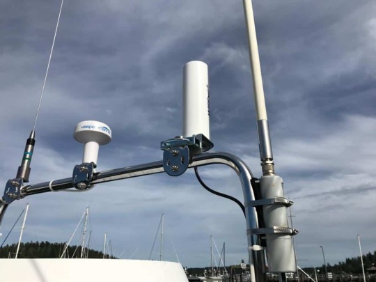
Most anglers know that your expensive and good quality boat will be useless when you are having a poor or a second-rate antenna. A quality radio antenna is definitely reliable and has a good performance in any marine radio. From the largest seagoing ships to the smallest ones, your antennas must be held up for years under the worst marine conditions. And it performs to their best and maximum design capabilities. In order to know how the VHF antennas work, I will show you how to choose, configure and test a marine radio antenna. How to Choose Marine Radio Antenna

Besides, a radio is the means of communication between the shore and the sea. Now, let me show you how to choose the right marine radio antenna for you! Antenna Length Length is one of the major factors you need to consider when choosing an antenna. Antennas can range from inches to over 20 feet. Because of many sizes made for your vessel, you can have a shorter antenna for convenience and portability for better communication. VHF radio only works on the line of sight principle. Two Kinds of Antenna Length Physical length refers to the measurement of the length of the “non-conducting” whip. The other one is the electrical length. Electrical length refers to the “operating” length of the antenna that is based on its electrical structure. When choosing the best marine radio antenna you’ll need to determine the range you need. If the VHF devices are a line of sight, the power of the signal depends on the length of the antenna. That is why length matters! Therefore, the taller the antenna, the better the signal you’ll gain and reach! Materials Used The internal and external components of the antenna are also important. It will affect the quality of transmission and reception. Antennas that will definitely give you the highest performance are made of stainless steel and fiberglass. There are also four main elemental cores used. These are brass tubing, copper wire, copper and brass tubing, and silver-plated brass tubing. Low Quality The low-cost antennas are made from stripped down coaxial cable that was held in place with foam inserts. This kind of antenna is non-metallic ferrules, less robust fiberglass housing ad crimped internal connections. They are also often made of nylon or plastic ferrules which are not durable. But this low-quality antenna will only reduce the performance of your VHF radio. Medium Quality Medium quality has a better quality antenna. It often comes with twin brass and copper radiators that will boost the performance of your device. They are moderately priced antennas that have often silver plated brass elements. They are also good for recreational boaters and anglers. High Quality These high-quality antennas have polyurethane coating which is more durable because they are polished with high-grade stainless steel ferrule. They are also popular and great to use for bigger ships and vessels that always and routinely go out. How to Configure a Marine Radio Antenna

The installation of a marine radio antenna is also important. You might need to consider the follows tips to make sure that your installation is right. As high as possible, mount the antenna because the number one rule is: the higher the antenna, the better the range.Make sure that the fiberglass is not vertically close to any metal object for it can change the radiation pattern of your antenna.You have to rout the coax exactly so it will not deform or pinch. Just keep it as far as possible from other metal, electronics, and cable. Keep it to at least 3 feet from the cable to the antenna is the best tip to do.A good connection to the radio is also important. You must check the antenna cable for any sign of damage or breakdown from sun exposure. The connectors must always be soldered to the end of the coaxial cable properly screwed into the radio’s antenna port.Do not also sue “antenna combiners”. They allow the same antenna to use on both AM and FM broadcast receiver.You can also cut the coax and support the antenna properly.Keep the antenna tuner close to the antenna.Use amplifiers when needed.High-quality coaxial cable and connectors are excellent to have consistent signal strength.If you want to clean the antenna, do not use cleaning solvents, adhesives, or other chemicals. Don’t let them near the antenna. This will definitely destroy the antennas finish. If you want to clean it, use a mild dish washing liquid. How to Test a Marine Radio Antenna

Buying those expensive antennas will be worthless if you do not know how to test it. Now, I will give you the following ideas and knowledge on how to test a marine radio antenna. It is also possible to make an on-the-air radio check by asking for a confirmation from another boat when you receive the message.Avoid using Channel 16. This is for mailing purposes only.You can also switch your radio power to low power which is basically 1 watt and monitor yourself on handheld VHF.Turn down the volume. And keep it as far as possible from the main radio and your antenna to avoid a loud feedback squeal from the portable set.Another way to test that your radio is transmitting is to watch your boat’s ampere meter when you are depressing your radio’s mike transmit button. Operation Tips There is a common operation error which is called miss-setting radio’s channel mode. All marine radios can operate to three different channel groups: Canada, United States of America and even International. The incorrect channel-mode setting can give you the inability to communicate on some channels. Check the icon on your radios’ screen which indicates your radio’s operation. Conclusion Remember, low-quality antennas could possibly lead you to nowhere. Choose a great quality antenna for your great VHF device. Choose the best VHF antenna for your boating needs. I hope that this article on how to choose, configure and test a marine radio antenna will help you gain more knowledge and awareness. So make sure to choose wisely!

Read the full article
0 notes
Link
For just $25.32 Amateur radio operators praise the Firestik’s 4 foot 2-meter mobile antenna (Model 2M-4) due to its outstanding performance. The radiating element is a 6dBi 5/8 wave design. The core material is 3/8″ solid fiberglass wound with 19 Guage heavy insulated copper wire. The radiating element is approximately 45″ long and Covered with white, UV stabilized PVC shrink tubing. The antenna base threads are 3/8″-24. A combination angle bracket, u-bolt, hub plate and antenna stud is Foundation of the base antenna. This assembly will mount to the top of any mast up to 1.5″ in diameter. The kit comes with four (4) structural aluminum (6061) radials that measure 1/8″x 1/2″x 20″. Each is pre-drilled to mount to the hub plate. The antenna stud utilizes a standard SO-239 base for easy hook-up with any UHF (PL-259) terminated coaxial cable.
0 notes
Text
Insulation Adhesive Tape Market– Overview on Key Innovations 2027
Insulation Adhesive Tape Market: Introduction
Insulating tape is a safety tape used to cover and insulate wires, cables, and other materials that conduct electricity. It consists of a backing material, which is relatively thin and coated with adhesives. Backing material can be made of plastics, rubber, silicone, PVC, polyamide, and fiberglass cloth. Vinyl tape is more popular for industrial uses, as it provides efficient and enduring insulation. It is available in various colors; however, black is the commonly preferred color.
Read report Overview-
https://www.transparencymarketresearch.com/insulation-adhesive-tape-market.html
Insulation tapes is available in various sizes and grades for different industrial applications
Electrical tapes are made of insulating material, which is used cover wire joints or cuts
Key Drivers of Insulation Adhesive Tape Market
According to the UN Sustainable Clean Energy Report, demand for electricity rose by 5% in 2018 compared to that in 2017 in developing countries such as India, Bangladesh, and Nepal; and various African countries. The power sector accounts for major share of the demand for electricity. The Government of India has launched a rural electrification scheme “Deen Dayal Upadhyay Gram Jyoti Yojana” and invested US$ 11 Bn to achieve the goal. Thus, strategies implemented to develop the power infrastructure is expected to boost the demand for wires and cables, thereby driving the electrical insulation adhesive tape market.
Under the Paris Agreement, majority of developed and developing countries have joined hands to reduce carbon emission and keep the increase in average global temperature to below 2°C. These countries are transforming and shifting toward electric vehicles and producing renewable energy. In line with this target, the Indian railways is likely to be fully electrified by 2023. France is anticipated to ban the sales of petrol and diesel vehicles by 2030. Demand for charging stations has surged by 44% in 2018 compared to that in 2017. These moves by countries such as India and France are collectively propelling the demand for electric battery charging stations, thereby augmenting the sales of electrical insulation adhesive tape market.
Are you a start-up willing to make it big in the business? Grab an exclusive PDF sample of this report
Key Restraints of Insulation Adhesive Tape Market
Various substitutes for electrical and thermal insulation, namely wire nuts and heat-shrink tubing, are available in the market
Wire nuts are used to connect two or more wires together. These are available at a competitive price in comparison to insulating adhesive tapes.
Insulation Adhesive Tape Market: Application Segment
Polyester insulation adhesives tapes are commonly used in the electrical & electronics industry due to their high dielectric strength, excellent electrical properties, and good chemical as well as solvent resistance. Insulation of wiring & cores, LT/HT installations of transformers, panel installation, and wiring are some of the applications of insulation adhesives tapes in the electrical Industry.
REQUEST FOR COVID19 IMPACT ANALYSIS –
https://www.transparencymarketresearch.com/sample/sample.php?flag=covid19&rep_id=76481
Production of electric vehicles rose by 68% in 2018 compared to that in 2017. Electric car battery generates heat and voltage. A special acrylic film insulating adhesives tape has been designed by TESA, a leading U.S.-based manufacturer of insulation adhesives tapes, in order to safeguard users from excessive power surges. This tape is predicted to become one of the key components of the automobile industry in the near future.
In the telecom Industry, rubber insulation tapes play an important role in lose attenuation for wave transmission antennas. These tapes are made up of rubber combined with some additives to increase elasticity. These tapes do not contain any harmful substance that can affect the environment or human health.
Key Manufacturers in Insulation Adhesive Tape Market
Key manufacturers operating in the global insulation adhesive tape market include:
Nitto Denko Corporation
Pidilite Industries Ltd.
Achem Technology Corporation
tesa SE
3M
H.Dottie Company
Plymouth Rubber Company Inc.
Scapa Group plc
Coroplast
Denka Company Limited
Saint Gobain
Garco Manufacturing Company Inc.
Nichiban Company Ltd.
Read our Case study at :
https://www.transparencymarketresearch.com/casestudies/chemicals-and-materials-case-study
0 notes
Text
How to Choose Configure and Test a Marine Radio Antenna

How to Choose, Configure and Test a Marine Radio Antenna
Most anglers know that your expensive and good quality boat will be useless when you are having a poor or a second-rate antenna. A quality radio antenna is definitely reliable and has a good performance in any marine radio. From the largest seagoing ships to the smallest ones, your antennas must be held up for years under the worst marine conditions. And it performs to their best and maximum design capabilities. In order to know how the VHF antennas work, I will show you how to choose, configure and test a marine radio antenna. How to Choose Marine Radio Antenna

Besides, a radio is the means of communication between the shore and the sea. Now, let me show you how to choose the right marine radio antenna for you! Antenna Length Length is one of the major factors you need to consider when choosing an antenna. Antennas can range from inches to over 20 feet. Because of many sizes made for your vessel, you can have a shorter antenna for convenience and portability for better communication. VHF radio only works on the line of sight principle. Two Kinds of Antenna Length Physical length refers to the measurement of the length of the “non-conducting” whip. The other one is the electrical length. Electrical length refers to the “operating” length of the antenna that is based on its electrical structure. When choosing the best marine radio antenna you’ll need to determine the range you need. If the VHF devices are a line of sight, the power of the signal depends on the length of the antenna. That is why length matters! Therefore, the taller the antenna, the better the signal you��ll gain and reach! Materials Used The internal and external components of the antenna are also important. It will affect the quality of transmission and reception. Antennas that will definitely give you the highest performance are made of stainless steel and fiberglass. There are also four main elemental cores used. These are brass tubing, copper wire, copper and brass tubing, and silver-plated brass tubing. Low Quality The low-cost antennas are made from stripped down coaxial cable that was held in place with foam inserts. This kind of antenna is non-metallic ferrules, less robust fiberglass housing ad crimped internal connections. They are also often made of nylon or plastic ferrules which are not durable. But this low-quality antenna will only reduce the performance of your VHF radio. Medium Quality Medium quality has a better quality antenna. It often comes with twin brass and copper radiators that will boost the performance of your device. They are moderately priced antennas that have often silver plated brass elements. They are also good for recreational boaters and anglers. High Quality These high-quality antennas have polyurethane coating which is more durable because they are polished with high-grade stainless steel ferrule. They are also popular and great to use for bigger ships and vessels that always and routinely go out. How to Configure a Marine Radio Antenna

The installation of a marine radio antenna is also important. You might need to consider the follows tips to make sure that your installation is right. As high as possible, mount the antenna because the number one rule is: the higher the antenna, the better the range.Make sure that the fiberglass is not vertically close to any metal object for it can change the radiation pattern of your antenna.You have to rout the coax exactly so it will not deform or pinch. Just keep it as far as possible from other metal, electronics, and cable. Keep it to at least 3 feet from the cable to the antenna is the best tip to do.A good connection to the radio is also important. You must check the antenna cable for any sign of damage or breakdown from sun exposure. The connectors must always be soldered to the end of the coaxial cable properly screwed into the radio’s antenna port.Do not also sue “antenna combiners”. They allow the same antenna to use on both AM and FM broadcast receiver.You can also cut the coax and support the antenna properly.Keep the antenna tuner close to the antenna.Use amplifiers when needed.High-quality coaxial cable and connectors are excellent to have consistent signal strength.If you want to clean the antenna, do not use cleaning solvents, adhesives, or other chemicals. Don’t let them near the antenna. This will definitely destroy the antennas finish. If you want to clean it, use a mild dish washing liquid. How to Test a Marine Radio Antenna

Buying those expensive antennas will be worthless if you do not know how to test it. Now, I will give you the following ideas and knowledge on how to test a marine radio antenna. It is also possible to make an on-the-air radio check by asking for a confirmation from another boat when you receive the message.Avoid using Channel 16. This is for mailing purposes only.You can also switch your radio power to low power which is basically 1 watt and monitor yourself on handheld VHF.Turn down the volume. And keep it as far as possible from the main radio and your antenna to avoid a loud feedback squeal from the portable set.Another way to test that your radio is transmitting is to watch your boat’s ampere meter when you are depressing your radio’s mike transmit button. Operation Tips There is a common operation error which is called miss-setting radio’s channel mode. All marine radios can operate to three different channel groups: Canada, United States of America and even International. The incorrect channel-mode setting can give you the inability to communicate on some channels. Check the icon on your radios’ screen which indicates your radio’s operation. Conclusion Remember, low-quality antennas could possibly lead you to nowhere. Choose a great quality antenna for your great VHF device. Choose the best VHF antenna for your boating needs. I hope that this article on how to choose, configure and test a marine radio antenna will help you gain more knowledge and awareness. So make sure to choose wisely!

Read the full article
0 notes
Text
How to Choose Configure and Test a Marine Radio Antenna

How to Choose, Configure and Test a Marine Radio Antenna
Most anglers know that your expensive and good quality boat will be useless when you are having a poor or a second-rate antenna. A quality radio antenna is definitely reliable and has a good performance in any marine radio. From the largest seagoing ships to the smallest ones, your antennas must be held up for years under the worst marine conditions. And it performs to their best and maximum design capabilities. In order to know how the VHF antennas work, I will show you how to choose, configure and test a marine radio antenna. How to Choose Marine Radio Antenna

Besides, a radio is the means of communication between the shore and the sea. Now, let me show you how to choose the right marine radio antenna for you! Antenna Length Length is one of the major factors you need to consider when choosing an antenna. Antennas can range from inches to over 20 feet. Because of many sizes made for your vessel, you can have a shorter antenna for convenience and portability for better communication. VHF radio only works on the line of sight principle. Two Kinds of Antenna Length Physical length refers to the measurement of the length of the “non-conducting” whip. The other one is the electrical length. Electrical length refers to the “operating” length of the antenna that is based on its electrical structure. When choosing the best marine radio antenna you’ll need to determine the range you need. If the VHF devices are a line of sight, the power of the signal depends on the length of the antenna. That is why length matters! Therefore, the taller the antenna, the better the signal you’ll gain and reach! Materials Used The internal and external components of the antenna are also important. It will affect the quality of transmission and reception. Antennas that will definitely give you the highest performance are made of stainless steel and fiberglass. There are also four main elemental cores used. These are brass tubing, copper wire, copper and brass tubing, and silver-plated brass tubing. Low Quality The low-cost antennas are made from stripped down coaxial cable that was held in place with foam inserts. This kind of antenna is non-metallic ferrules, less robust fiberglass housing ad crimped internal connections. They are also often made of nylon or plastic ferrules which are not durable. But this low-quality antenna will only reduce the performance of your VHF radio. Medium Quality Medium quality has a better quality antenna. It often comes with twin brass and copper radiators that will boost the performance of your device. They are moderately priced antennas that have often silver plated brass elements. They are also good for recreational boaters and anglers. High Quality These high-quality antennas have polyurethane coating which is more durable because they are polished with high-grade stainless steel ferrule. They are also popular and great to use for bigger ships and vessels that always and routinely go out. How to Configure a Marine Radio Antenna

The installation of a marine radio antenna is also important. You might need to consider the follows tips to make sure that your installation is right. As high as possible, mount the antenna because the number one rule is: the higher the antenna, the better the range.Make sure that the fiberglass is not vertically close to any metal object for it can change the radiation pattern of your antenna.You have to rout the coax exactly so it will not deform or pinch. Just keep it as far as possible from other metal, electronics, and cable. Keep it to at least 3 feet from the cable to the antenna is the best tip to do.A good connection to the radio is also important. You must check the antenna cable for any sign of damage or breakdown from sun exposure. The connectors must always be soldered to the end of the coaxial cable properly screwed into the radio’s antenna port.Do not also sue “antenna combiners”. They allow the same antenna to use on both AM and FM broadcast receiver.You can also cut the coax and support the antenna properly.Keep the antenna tuner close to the antenna.Use amplifiers when needed.High-quality coaxial cable and connectors are excellent to have consistent signal strength.If you want to clean the antenna, do not use cleaning solvents, adhesives, or other chemicals. Don’t let them near the antenna. This will definitely destroy the antennas finish. If you want to clean it, use a mild dish washing liquid. How to Test a Marine Radio Antenna

Buying those expensive antennas will be worthless if you do not know how to test it. Now, I will give you the following ideas and knowledge on how to test a marine radio antenna. It is also possible to make an on-the-air radio check by asking for a confirmation from another boat when you receive the message.Avoid using Channel 16. This is for mailing purposes only.You can also switch your radio power to low power which is basically 1 watt and monitor yourself on handheld VHF.Turn down the volume. And keep it as far as possible from the main radio and your antenna to avoid a loud feedback squeal from the portable set.Another way to test that your radio is transmitting is to watch your boat’s ampere meter when you are depressing your radio’s mike transmit button. Operation Tips There is a common operation error which is called miss-setting radio’s channel mode. All marine radios can operate to three different channel groups: Canada, United States of America and even International. The incorrect channel-mode setting can give you the inability to communicate on some channels. Check the icon on your radios’ screen which indicates your radio’s operation. Conclusion Remember, low-quality antennas could possibly lead you to nowhere. Choose a great quality antenna for your great VHF device. Choose the best VHF antenna for your boating needs. I hope that this article on how to choose, configure and test a marine radio antenna will help you gain more knowledge and awareness. So make sure to choose wisely!

Read the full article
0 notes
Text
How to Choose Configure and Test a Marine Radio Antenna

How to Choose, Configure and Test a Marine Radio Antenna
Most anglers know that your expensive and good quality boat will be useless when you are having a poor or a second-rate antenna. A quality antenna is definitely reliable and has a good performance in any marine radio. From the largest seagoing ships to the smallest ones, your antennas must be held up for years under the worst marine conditions and performs to their best and maximum design capabilities. In order to know how the VHF antennas work, I will show you how to choose, configure and test a marine radio antenna. How to Choose Marine Radio Antenna

A radio is the means of communication between the shore and the sea. Now, let me show you how to choose the right marine radio antenna for you! Antenna Length Length is one of the major factors you need to consider when choosing an antenna. Antennas can range from inches to over 20 feet. Because of many sizes made for your vessel, you can have a shorter antenna for convenience and portability for a better communication. VHF radio only works on the line of sight principle. Two Kinds of Antenna Length Physical length refers to the measurement of the length of the “non-conducting” whip. The other one is the electrical length. Electrical length refers to the “operating” length of the antenna that is based on its electrical structure. When choosing the best marine radio antenna you’ll need to determine the range you need. If the VHF devices are a line of sight, the power of the signal depends on the length of the antenna. That is why length matters! Therefore, the taller the antenna, the better the signal you’ll gain and reach! Materials Used The internal and external components of the antenna are also important. It will affect the quality of transmission and reception. Antennas that will definitely give you the highest performance are made of stainless steel and fiberglass. There are also four main elemental cores used, these are brass tubing, copper wire, copper and brass tubing, and silver-plated brass tubing. Low Quality The low-cost antennas are made from stripped down coaxial cable that was held in place with foam inserts. This kind of antenna is non-metallic ferrules, less robust fiberglass housing ad crimped internal connections. They are also often made of nylon or plastic ferrules which are not durable. This low-quality antenna will only reduce the performance of your VHF radio. Medium Quality Medium quality has a better quality antenna. They often come with twin brass and copper radiators that will boost the performance of your device. They are moderately priced antennas that have often silver plated brass elements. They are also good for recreational boaters and anglers. High Quality These high-quality antennas have polyurethane coating which is more durable because they are polished with high-grade stainless steel ferrule. They are also popular and great to use for bigger ships and vessels that always and routinely go out. How to Configure a Marine Radio Antenna

The installation of a marine radio antenna is also important. You might need to consider the follows tips to make sure that your installation is right. As high as possible, mount the antenna because the number one rule is: the higher the antenna, the better the range. Make sure that the fiberglass is not vertically close to any metal object for it can change the radiation pattern of your antenna. You have to rout the coax exactly so it will not be deformed or pinched. Just keep it as far as possible from other metal, electronics, and cable. Keep it to at least 3 feet from the cable to the antenna is the best tip to do. A good connection to the radio is also important. You must check the antenna cable for any sign of damage or breakdown from sun exposure. The connectors must always be soldered to the end of the coaxial cable properly screwed into the radio’s antenna port. Do not also sue “antenna combiners”. They allow the same antenna to be used on both AM and FM broadcast receiver. You can also cut the coax and support the antenna properly. Keep the antenna tuner close to the antenna. Use amplifiers when needed. High-quality coaxial cable and connectors are excellent to have consistent signal strength. If you want to clean the antenna, do not use cleaning solvents, adhesives, or other chemicals. Don’t let them near the antenna. This will definitely destroy the antennas finish. If you want to clean it, use a mild dish washing liquid. How to Test a Marine Radio Antenna

Buying those expensive antennas will be worthless if you do not know how to test it. Now, I will give you the following ideas and knowledge on how to test a marine radio antenna. It is also possible to make an on-the-air radio check by asking for a confirmation from another boat when the message is received from you. Avoid using Channel 16. This is for mailing purposes only. You can also switch your radio power to low power which is basically 1 watt and monitor yourself on handheld VHF. Turn down the volume and keep it as far as possible from the main radio and your antenna to avoid a loud feedback squeal from the portable set. Another way to test that your radio is transmitting is to watch your boat’s ampere meter when you are depressing your radio’s mike transmit button. Operation Tips There is a common operation error which is called miss-setting radio’s channel mode. All marine radios can operate to three different channel groups: Canada, United States of America and even International. The incorrect channel-mode setting can give you the inability to communicate on some channels. Check the icon on your radios’ screen which indicates your radio’s operation. Conclusion Remember, low-quality antennas could possibly lead you to nowhere. Choose a great quality antenna for your great VHF device. Choose the best VHF antenna for your boating needs. I hope that this article on how to choose, configure and test a marine radio antenna will help you gain more knowledge and awareness and make sure to choose wisely! Facebook Twitter Instagram Pinterest Google-plus Android

Read the full article
0 notes
Text
How to Choose Configure and Test a Marine Radio Antenna

How to Choose, Configure and Test a Marine Radio Antenna
Most anglers know that your expensive and good quality boat will be useless when you are having a poor or a second-rate antenna. A quality antenna is definitely reliable and has a good performance in any marine radio. From the largest seagoing ships to the smallest ones, your antennas must be held up for years under the worst marine conditions and performs to their best and maximum design capabilities. In order to know how the VHF antennas work, I will show you how to choose, configure and test a marine radio antenna. How to Choose Marine Radio Antenna

A radio is the means of communication between the shore and the sea. Now, let me show you how to choose the right marine radio antenna for you! Antenna Length Length is one of the major factors you need to consider when choosing an antenna. Antennas can range from inches to over 20 feet. Because of many sizes made for your vessel, you can have a shorter antenna for convenience and portability for a better communication. VHF radio only works on the line of sight principle. Two Kinds of Antenna Length Physical length refers to the measurement of the length of the “non-conducting” whip. The other one is the electrical length. Electrical length refers to the “operating” length of the antenna that is based on its electrical structure. When choosing the best marine radio antenna you’ll need to determine the range you need. If the VHF devices are a line of sight, the power of the signal depends on the length of the antenna. That is why length matters! Therefore, the taller the antenna, the better the signal you’ll gain and reach! Materials Used The internal and external components of the antenna are also important. It will affect the quality of transmission and reception. Antennas that will definitely give you the highest performance are made of stainless steel and fiberglass. There are also four main elemental cores used, these are brass tubing, copper wire, copper and brass tubing, and silver-plated brass tubing. Low Quality The low-cost antennas are made from stripped down coaxial cable that was held in place with foam inserts. This kind of antenna is non-metallic ferrules, less robust fiberglass housing ad crimped internal connections. They are also often made of nylon or plastic ferrules which are not durable. This low-quality antenna will only reduce the performance of your VHF radio. Medium Quality Medium quality has a better quality antenna. They often come with twin brass and copper radiators that will boost the performance of your device. They are moderately priced antennas that have often silver plated brass elements. They are also good for recreational boaters and anglers. High Quality These high-quality antennas have polyurethane coating which is more durable because they are polished with high-grade stainless steel ferrule. They are also popular and great to use for bigger ships and vessels that always and routinely go out. How to Configure a Marine Radio Antenna

The installation of a marine radio antenna is also important. You might need to consider the follows tips to make sure that your installation is right. As high as possible, mount the antenna because the number one rule is: the higher the antenna, the better the range. Make sure that the fiberglass is not vertically close to any metal object for it can change the radiation pattern of your antenna. You have to rout the coax exactly so it will not be deformed or pinched. Just keep it as far as possible from other metal, electronics, and cable. Keep it to at least 3 feet from the cable to the antenna is the best tip to do. A good connection to the radio is also important. You must check the antenna cable for any sign of damage or breakdown from sun exposure. The connectors must always be soldered to the end of the coaxial cable properly screwed into the radio’s antenna port. Do not also sue “antenna combiners”. They allow the same antenna to be used on both AM and FM broadcast receiver. You can also cut the coax and support the antenna properly. Keep the antenna tuner close to the antenna. Use amplifiers when needed. High-quality coaxial cable and connectors are excellent to have consistent signal strength. If you want to clean the antenna, do not use cleaning solvents, adhesives, or other chemicals. Don’t let them near the antenna. This will definitely destroy the antennas finish. If you want to clean it, use a mild dish washing liquid. How to Test a Marine Radio Antenna

Buying those expensive antennas will be worthless if you do not know how to test it. Now, I will give you the following ideas and knowledge on how to test a marine radio antenna. It is also possible to make an on-the-air radio check by asking for a confirmation from another boat when the message is received from you. Avoid using Channel 16. This is for mailing purposes only. You can also switch your radio power to low power which is basically 1 watt and monitor yourself on handheld VHF. Turn down the volume and keep it as far as possible from the main radio and your antenna to avoid a loud feedback squeal from the portable set. Another way to test that your radio is transmitting is to watch your boat’s ampere meter when you are depressing your radio’s mike transmit button. Operation Tips There is a common operation error which is called miss-setting radio’s channel mode. All marine radios can operate to three different channel groups: Canada, United States of America and even International. The incorrect channel-mode setting can give you the inability to communicate on some channels. Check the icon on your radios’ screen which indicates your radio’s operation. Conclusion Remember, low-quality antennas could possibly lead you to nowhere. Choose a great quality antenna for your great VHF device. Choose the best VHF antenna for your boating needs. I hope that this article on how to choose, configure and test a marine radio antenna will help you gain more knowledge and awareness and make sure to choose wisely! Facebook Twitter Instagram Pinterest Google-plus

Read the full article
0 notes
Photo

C&T RF Antennas Inc - Gray color N Plug connector fiberglass antennas 2.4G & 5.8G frequency
#C&T RF Antennas Inc#fiberglass antenna cover#fiberglass antenna support#fiberglass antenna mast base#fiberglass antenna amazon#comet antenna gp-9#arrow antenna gp#gp antenna balun#are fiberglass cb antennas good#fiberglass rods for antennas#fiberglass tubing for antennas
0 notes