#esp32 wroom32
Explore tagged Tumblr posts
Text

Controller Area Network (CAN) Development with the ESP32
The ESP32 processor, including the various development kits, is perfect for Controller Area Network (CAN) and Internet of Things (IoT) prototyping applications. It provides multiple on-chip resources, including a CAN controller, WIFI, Bluetooth, BLE, UART, SPI, and more.
0 notes
Text

ESP32 Board, Wifi Bluetooth Integrated Dual Core Nodemcu ESP32 Development Board integrates antenna switch, RF balun, power amplifier, low noise amplifier, filter and power management module, and the whole solution takes up a small circuit board area. 2.4 GHz Wi-Fi plus Bluetooth dual-mode chip Using TSMC low-power 40nm technology, it has excellent power consumption performance and RF performance, is reliable, and can be easily expanded to various applications. USB Driver:CP2102 Core Chip:esp32 wroom32 Micro and Type-C interface available,same price Packing list of the esp32 board: ESD Packing. Welcome contact us to talk if your quantity is much more than online MOQ.Know more about our company business. Read the full article
0 notes
Text
Price: [price_with_discount] (as of [price_update_date] - Details) [ad_1] Product Description Product description ESP32 is already integrated antenna and rf balun, power amplifier, low-noise amplifiers, filters, and power management module. The entire solution takes up the least amount of printed circuit board area. This board is used with 2. 4 GHz dual-mode wi-fi and Bluetooth chips by tsmc 40nm low power technology, power and rf properties best, which is safe, reliable, and scalable to a variety of applications. Features performance ratio Small volume, easily embedded to other products Strong function with support lwip protocol, freertos supporting three modes: Ap, sta, and ap+sta supporting Lua program, easily to develop. ESP32 ESP-32 ESP-32S ESP 32 Development Board CP2102 WiFi Bluetooth Ultra-Low Power Consumption Dual Core (38 PIN). The development board combines a CPU with 2 Tensilica LX6 cores, clocked at up to 240 MHz, and 512 kilobytes SRAM in a single microcontroller chip. ESP32 Development board is based on the ESP WROOM32 WIFI + BLE Module. It's a low-footprint, minimal system development board powered by the latest ESP-WROOM-32 module and can be easily inserted into a solderless breadboard. It contains the entire basic support circuitry for the ESP-WROOM-32, including the USB-UART bridge, reset- and boot-mode buttons, LDO regulator, and a micro-USB connector. Every important GPIO is available to the developer. The entire solution takes up the least amount of printed circuit board area this board is used with 24 ghz dual-mode wi-fi and bluetooth chips by tsmc 40nm low power technology, power and rf properties best, which is safe, reliable, and scalable to a variety of applications Features: High performance-price ratio small volume, easily embeded to other products strong function with support lwip protocol, freertos supporting three modes: Ap, sta, and ap+sta supporting lua program, easily to develop [ad_2]
0 notes
Text
ESP32 mit RFID-RC522 (MFRC522) Modul
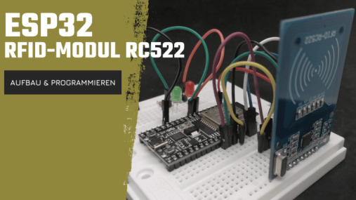
In diesem Beitrag möchte ich dir zeigen, wie du ein RFID Modul vom Typ MFRC522 am ESP32 per SPI programmierst, möchte ich dir hier zeigen.
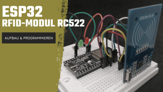
Programmieren & Anschluss eines RFID-Moduls am ESP32 Das RFID Modul habe ich dir bereits für die Mikrocontroller der Arduino-Familie in folgenden Beiträgen gezeigt: - Arduino Lektion 20 – Teil 1: RFID RC522 – Kartenleser - RFID Kartenleser RC522 am Arduino betreiben (Update 29.07.2021) - Arduino Projekt: PIR & RFID Alarmanlage
Benötigte Ressourcen für dieses Projekt
Wenn du das nachfolgende Beispiel nachbauen möchtest, dann benötigst du: - einen ESP32 zbsp. ESP32-WROOM-32*, - ein Micro-USB Datenkabel, - ein RFID Modul Typ MFRC522, - ein paar Breadboardkabel, - ein 170 Pin Breadboard * Leider hat nicht jeder ESP32 alle Pins nach außen geführt und somit empfehle ich dir den ESP32-WROOM-32 von - LILYGO® TTGO T-Call V1.4 ESP32 Wireless Module SIM Antenna SIM Card SIM800L Module - ESP32-WROOM-32, DevKit C4 WROOM32 Für die optische Signalisierung einer gültigen RFID Karte nutze ich zwei 5 mm LEDs (rot & grün). Diese beiden LEDs benötigen noch zusätzlich einen 220 Ohm Vorwiderstand und natürlich Breadboardkabel.
ESP32 auf einem Breadboard
Normalerweise verwende ich für die Schaltungen immer ein Breadboard (400 Pin oder 720 Pin), jedoch ist der ESP32 für das "normale" 400 Pin Breadboard zu breit und man kann lediglich nur eine Pinleiste mit Breadboardkabel abgreifen. Aus dem Conrad Adventskalender sowie einem Franzis Bausatz habe ich zwei 270 Pin Breadboards welche zusammengesteckt werden können und der ESP32 sehr gut darauf passt.

ESP32 auf 400 Pin Breadboard

ESP32 auf 2 gesteckte Breadboards Alternativ kannst du auch mit Breadboardkabel (männlich - weiblich) direkt an die Pins des ESPs gehen.
RFID-RC522 Modul als Set
Das in diesem Beitrag verwendete RFID-RC522 Modul erhältst du als Set mit einer Karte sowie einem Schlüsselanhänger.
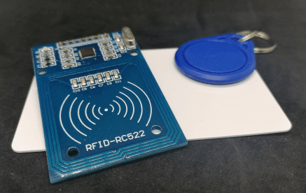
RFID-RC522 Modul mit Karte & Schlüsselanhänger
Aufbau der Schaltung
Das RFID Modul wird per SPI angeschlossen und die Schaltung sieht wie folgt aus:
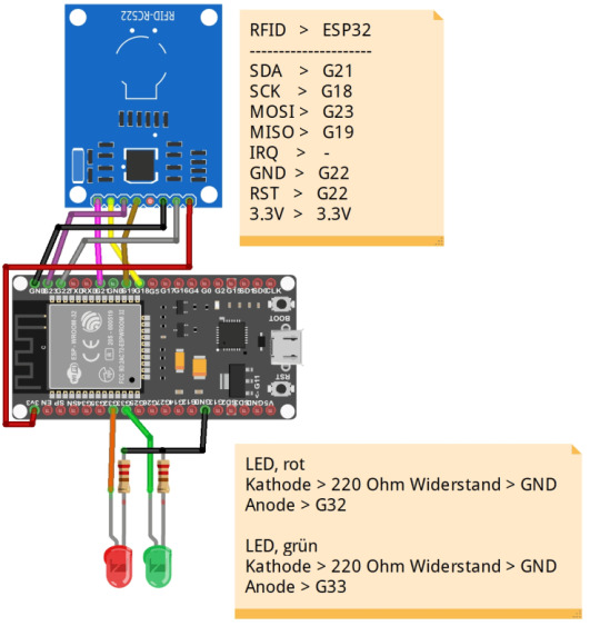
Schaltung - RFID Modul am ESP32 (inkl. LEDs) Wie bereits erwähnt habe ich den ESP32 auf zwei 270 Pin Breadboards gesteckt und kann die LEDs sowie das RFID Modul auf den freien Platz des Breadboard stecken.

Aufbau der Schaltung "ESP32 mit RFID-Modul Typ MFRC522 & LEDs"
Programmieren
Für die Programmierung des RFID Moduls verwende ich die Bibliothek "MFRC522 by GithubCommunity" welche du im Bibliotheksverwalter der Arduino IDE herunterladen kannst. Im Bibliotheksverwalter suchst du zunächst nach "rc522" und betätigst dann die Schaltfläche "Installieren" im Suchergebnis "MFRC522 by GithubCommunity".

Wenn die Installation abgeschlossen wurde, kann das Fenster über die Schaltfläche "Schließen" geschlossen werden und mit der Programmierung begonnen werden. In den folgenden Schritten werde ich dir zeigen, wie du ein kleines Programm erstellst, welches eine RFID-ID zulässt und eine nicht.
Schritt 1 - auslesen der RFID Karten
Damit wir eine RFID Karte einen Zugang gewähren können, müssen wir die IDs zunächst auslesen. Dazu können wir entweder das Beispielprogramm "Beispiele" > "MFRC522" > "DumpInfo" oder das nachfolgende kleine Programm. //einbinden der Bibliotheken für das //ansteuern des MFRC522 Moduls #include #include //definieren der Pins RST & SDA für den ESP32 #define RST_PIN 22 #define SS_PIN 21 //erzeugen einer Objektinstanz MFRC522 mfrc522(SS_PIN, RST_PIN); //Variable zum speichern der bereits gelesenen RFID-ID String lastRfid = ""; void setup() { //beginn der seriellen Kommunikation mit 115200 Baud Serial.begin(115200); //eine kleine Pause von 50ms. delay(50); //begin der SPI Kommunikation SPI.begin(); //initialisieren der Kommunikation mit dem RFID Modul mfrc522.PCD_Init(); } void loop() { //Wenn keine neue Karte vorgehalten wurde oder die serielle Kommunikation //nicht gegeben ist, dann... if ( ! mfrc522.PICC_IsNewCardPresent() || ! mfrc522.PICC_ReadCardSerial()) { return; } String newRfidId = ""; for (byte i = 0; i < mfrc522.uid.size; i++) { // !! Achtung es wird ein Leerzeichen vor der ID gesetzt !! newRfidId.concat(mfrc522.uid.uidByte < 0x10 ? " 0" : " "); newRfidId.concat(String(mfrc522.uid.uidByte, HEX)); } //alle Buchstaben in Großbuchstaben umwandeln newRfidId.toUpperCase(); //Wenn die neue gelesene RFID-ID ungleich der bereits zuvor gelesenen ist, //dann soll diese auf der seriellen Schnittstelle ausgegeben werden. if (!newRfidId.equals(lastRfid)) { //überschreiben der alten ID mit der neuen lastRfid = newRfidId; Serial.print(" gelesene RFID-ID :"); Serial.println(newRfidId); Serial.println(); } } Wenn man nun eine RFID-Karte vor das RFID-Modul hält, dann wird diese ID auf der seriellen Schnittstelle ausgegeben. Da im Programm die letzte, erfolgreich, gelesene ID zwischengespeichert wird, erfolgt bei erneutem Vorlegen der Karte keine neue Ausgabe.

Ausgabe des Programmes zum lesen einer RFID-ID am ESP32
Schritt 2 - erzeugen eines Arrays mit zulässigen RFID-IDs
Wie erwähnt liegen dem Set des RFID Moduls bereits zwei RFID Karten, bei welche wir im ersten Schritt ausgelesen haben. //Anzahl der zulässigen RFID-IDs im Array const int NUM_RFIDS = 1; //Array mit RFID-IDs welche zulässig sind String rfids = {"39 42 FF 97"}; void loop() { ... bool zugangOk = false; for (int i = 0; i < NUM_RFIDS; i++) { if (rfids.equals(newRfidId)) { zugangOk = true; break; } }
Schritt 3 - LEDs zum optischen Signalisieren einer zulässigen RFID-ID
Im nächsten Schritt wollen wir nun die rote LED blinken lassen, wenn der Zugang nicht gewährt wird, bzw. die RFID-ID nicht im Array vorhanden ist und die grüne LED soll blinken, wenn der Zugang gewährt werden soll. Des Weiteren soll auf der seriellen Schnittstelle eine entsprechende Ausgabe erfolgen. //einbinden der Bibliotheken für das //ansteuern des MFRC522 Moduls #include #include //definieren der Pins RST & SDA für den ESP32 #define RST_PIN 22 #define SS_PIN 21 #define ledRot 32 #define ledGruen 33 //erzeugen einer Objektinstanz MFRC522 mfrc522(SS_PIN, RST_PIN); //Variable zum speichern der bereits gelesenen RFID-ID String lastRfid = ""; //Anzahl der zulässigen RFID-IDs im Array const int NUM_RFIDS = 1; //Array mit RFID-IDs welche zulässig sind String rfids = {" 39 42 FF 97"}; void setup() { //beginn der seriellen Kommunikation mit 115200 Baud Serial.begin(115200); //eine kleine Pause von 50ms. delay(50); pinMode(ledRot, OUTPUT); pinMode(ledGruen, OUTPUT); //begin der SPI Kommunikation SPI.begin(); //initialisieren der Kommunikation mit dem RFID Modul mfrc522.PCD_Init(); } void loop() { //Wenn keine neue Karte vorgehalten wurde oder die serielle Kommunikation //nicht gegeben ist, dann... if ( !mfrc522.PICC_IsNewCardPresent()) { //Serial.println("!PICC_IsNewCardPresent"); return; } if (!mfrc522.PICC_ReadCardSerial()) { //Serial.println("!PICC_ReadCardSerial"); return; } String newRfidId = ""; for (byte i = 0; i < mfrc522.uid.size; i++) { newRfidId.concat(mfrc522.uid.uidByte < 0x10 ? " 0" : " "); newRfidId.concat(String(mfrc522.uid.uidByte, HEX)); } //alle Buchstaben in Großbuchstaben umwandeln newRfidId.toUpperCase(); //Wenn die neue gelesene RFID-ID ungleich der bereits zuvor gelesenen ist, //dann soll diese auf der seriellen Schnittstelle ausgegeben werden. if (!newRfidId.equals(lastRfid)) { //überschreiben der alten ID mit der neuen lastRfid = newRfidId; } bool zugangOk = false; //prüfen ob die gelesene RFID-ID im Array mit bereits gespeicherten IDs vorhanden ist for (int i = 0; i < NUM_RFIDS; i++) { //wenn die ID an der Stelle "i" im Array "rfids" mit dem gelesenen übereinstimmt, dann if (rfids.equals(newRfidId)) { zugangOk = true; //Schleife verlassen break; } } //Wenn die Variable "zugangOk" auf True ist, dann... if (zugangOk) { blinkLed(ledGruen); Serial.println("RFID-ID OK!, Zugang wird gewährt"); } else { //Wenn nicht dann... blinkLed(ledRot); Serial.println("RFID-ID nicht OK!, Zugang wird nicht gewährt"); } Serial.println(); } //Blinken einer LED am Pin "pin" void blinkLed(int pin) { //Schleife von 0 bis 5 for (int a = 0; a < 5; a++) { //LED aktivieren digitalWrite(pin, HIGH); //eine Pause von 125 ms. delay(125); //LED deaktivieren digitalWrite(pin, LOW); //eine Pause von 125 ms. delay(125); } }
Download des fertigen Programmes
Hier nun ein Link zum Herunterladen des fertigen Programmes. Read the full article
0 notes
Text
Invest in IoT Devices and Enjoy Their Amazing Quality
Buying the highest quality Arduino Data Logger Temperature is only a step away from you. Simply visit Norvi as it is a leading platform offering a wide range of products available at quite reasonable prices. Invest in Arduino Data Logger Temperature with confidence and be sure it is a great electronic device that can store a number of measurements.
Using a data logger allows people enjoy more accurate measurements.
They can be taken automatically and data logging will not be subject to human error.
Data loggers are needed for various reasons, especially for making sure compliance with industry specific regulations, as well as quality and environmental control procedures. Opt for this data logger and it will certainly help to save costs through energy efficiency/environmental management.
Other than real-time acquisition and pushing to an IoT platform, data loggers are one method of keeping track of values and analyzing. The industrial world is full of various types of data loggers and they are as follows. USB loggers which are used for Short-term trend logging with manual offload, Bluetooth (BLE) Loggers with Wireless data access via mobile devices, Web-based Systems with Long-range wireless internet access, as well as Wireless Sensors with Short-range centralized data collection.
Norvi is a top choice and this team is proud of working with the most outstanding enclosure manufacturers around the world, to provide you the best solutions for enclosing the product for protection. This company works based on the requirements of installation, and environments so that you will get the best product range such as:
NORVI Cema
Norvi IIOT
NORVI ENET
NORVI Arita
Agent 1
Agent 2
Expansion Modules
M11 E Series
M11 B Series
M12 B Series
M12 C Series
NORVI IIOT stands out due to many features:
ESP32-WROOM32 Module
Built-in 0.96 OLED Display
Built-in Button on front panel
Digital Inputs
Industrial Standard Analog Inputs
Relay Outputs
DIN-Rail mount
Supports Expansion port
NORVI ENET is another popular product offered by Norvi. Like NORVI IIOT, it also has its specific features:
ESP32-WROOM32 Module
W5500 Ethernet Connectivity
Built-in 0.96 OLED Display
Digital Inputs
Industrial Standard Analog Inputs
Relay Outputs
DIN-Rail mount
You can also get the needed technical support and have a successful project. Fast turn-around time is also guaranteed. The experts have ready to use products, which you can start your concept development on, while a device is being tailor made for you.
Norvi is a great destination where you can come across the highest quality data loggers and enjoy the best quality. All you need to visit the website and a wide range of products will be at your disposal. Look no further and choose Norvi because this is the most trustworthy source for buying affordable and the highest quality devices.
0 notes
Text
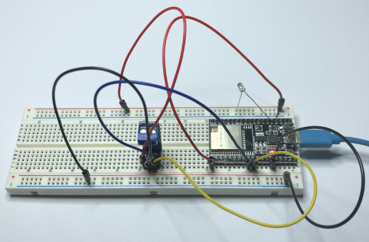
CAN Bus Development with ESP32-WROOM32 Development Board
The ESP32 WiFi, Bluetooth Classic, BLE, CAN Bus Module comes with an onboard ESP32 WROOM-32 WiFi, Bluetooth Classic, BLE Module, and a CAN Bus port with a transceiver. The programming is accomplished through the popular Arduino IDE connected to the USB-to-Serial converter with a USB-C connector, automatic bootloader, and reset.
#can bus#classic can#esp32#embedded programming#embedded systems#wroom32#wifi#ble#bluetooth#usb#gateway#iot
1 note
·
View note
Text
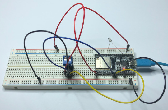
CAN Bus Development with ESP32-WROOM32 Development Board
The ESP32 integrates a CAN Bus controller compatible with the NXP SJA1000. Thus, it is CAN 2.0B specification compliant. As with the SJA1000, the ESP32 CAN Bus controller provides only the data link layer and the physical layer signaling sublayer. Therefore, an external transceiver module is required, which converts the CAN-RX and CAN-TX signals of the ESP32 into CAN_H and CAN_L bus signals. The transceiver, such as the MCP2551 or SN65HVD23X, provides compatibility with ISO 11898-2.
1 note
·
View note
Text
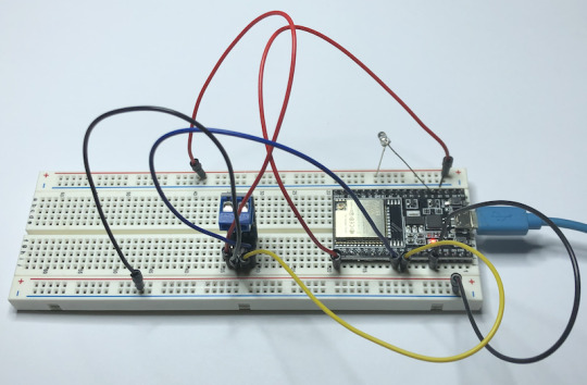
CAN Bus Development with ESP32-WROOM32 Development Board
This post will demonstrate how to add a CAN Bus port to the ESP32-WROOM32 development board, i.e., regarding hardware and software.
https://copperhilltech.com/blog/can-bus-development-with-esp32wroom32-development-board/
0 notes
Text

CAN Bus Development with ESP32-WROOM32 Development Board
The ESP32 WiFi, Bluetooth Classic, BLE, CAN Bus Module comes with an onboard ESP32 WROOM-32 WiFi, Bluetooth Classic, BLE Module, and a CAN Bus port with a transceiver. The programming is accomplished through the popular Arduino IDE connected to the USB-to-Serial converter with USB-C connector, automatic bootloader and reset.
0 notes
Text
Customized Product Development by Norvi
Visit Norvi and you will certainly receive the customized product development you deserve. Rely on this professional team and be sure to to enjoy a lot of benefits such as:
Lowered costs for scaled integration
Dedicated hardware for optimum performance
Support throughout the lifecycle
In-house prototyping
Manufacturing
The main step the experts identify is Input and Output requirements. What it should sense or actuate, decides the hardware we need to use within the device. Always count on this professional team that stands out due to the in-depth knowledge of the various types of actuators and sensors. This will make you go for the most cost effective and reliable solution. Reliable communication methods are also selected, with the power consumption, bandwidth, and cost limitations. Norvi prides itself on working with the most outstanding enclosure manufacturers around the world, to provide you the best solutions for enclosing the product for protection. This company works based on the requirements of installation, and environments so that you will get the best product range such as:
NORVI Cema
Norvi IIOT
NORVI ENET
NORVI Arita
Agent 1
Agent 2
Expansion Modules
M11 E Series
M11 B Series
M12 B Series
M12 C Series
NORVI IIOT stands out due to many features:
ESP32-WROOM32 Module
Built-in 0.96 OLED Display
Built-in Button on front panel
Digital Inputs
Industrial Standard Analog Inputs
Relay Outputs
DIN-Rail mount
Supports Expansion port
NORVI ENET is another popular product offered by Norvi. Like NORVI IIOT, it also has its specific fetaures:
ESP32-WROOM32 Module
W5500 Ethernet Connectivity
Built-in 0.96 OLED Display
Digital Inputs
Industrial Standard Analog Inputs
Relay Outputs
DIN-Rail mount
Norvi has a skilled team with excellent skills in every phase of IoT product development. Due to the in-house manufacturing and assembly, you will be able to save a lot of time. Besides, it will also add flexibility to the process. These experts are able to respond to design changes well and workout the best for the project. The best part is that they have already worked in many IoT Devices and software platforms which means that you can always trust this product developer. You can also get the needed technical support and have a successful project. Fast turn-around time is also guaranteed. The experts have ready to use products, which you can start your concept development on, while a device is being tailor made for you.
Norvi also offers you Esp32 Based Ethernet Device for you. Order now and take advantage of this USB Programmable Industrial ESP32 with OLED Display and din-rail mount. NORVI ENET Series comes with built-in Ethernet which expands its connectivity. NORVI ENET range is the idea choice for ESP32 Ethernet implementations, where industrial level I/O and voltages are present. ESP32 Ethernet provides both Wireless and wired connections to the network. It is designed for protection and reliability. Moreover, it also complies with 2014/30/EU- Electromagentic Compatibility (EMC) Annex III, Part B, Module C (Conformity to Type Based on Internal Production Control). If you need Esp32 Based Ethernet Device or other types of devices, simply visit Norvi today!
0 notes
Text

Adafruit HUZZAH32 – ESP32 Feather Board for IoT Applications
The HUZZAH32 is an ESP32-based Feather made with the official WROOM32 module. In addition, it comes with a built-in USB-to-Serial converter, automatic bootloader reset, Lithium Ion/Polymer charger, and all of the GPIOs brought out for use with any Feather Wings.
https://copperhilltech.com/adafruit-huzzah32-esp32-feather-board-for-iot-applications/
0 notes