#electromagnetic eddy current brake
Explore tagged Tumblr posts
Visit Tumblr Blog
Explore Tumblr blogs with no restrictions, modern design and the best experience.
Last Seen Tumblr Blogs


Fun Fact
Tumblr has been providing a Korean-language service since 2013.
Text
The Role of Eddy Currents in Renewable Energy Systems
In the quest for sustainable energy solutions, the role of eddy currents has emerged as a significant factor in enhancing the efficiency of renewable energy systems. This blog delves into the mechanics of eddy currents, their applications in various renewable energy technologies, and their impact on system performance. Additionally, we will explore the importance of Heat Exchanger Tube Cleaning in optimizing these systems, ensuring they operate at peak efficiency.

Understanding Eddy Currents
Eddy currents are loops of electric current that are induced within conductors by a changing magnetic field. When a conductor is exposed to a magnetic field that varies in strength or direction, it generates swirling currents that flow in closed loops. These currents are a byproduct of electromagnetic induction and can lead to energy losses in electrical systems. However, when harnessed correctly, eddy currents can be utilized to improve the efficiency of renewable energy systems.
Applications of Eddy Currents in Renewable Energy
Wind Energy
In wind turbines, eddy currents can be both a challenge and an opportunity. The rotating blades of a wind turbine create a changing magnetic field, which can induce eddy currents in nearby conductive materials. While these currents can lead to energy losses through heat generation, they can also be used in certain applications, such as in the design of magnetic brakes. These brakes utilize eddy currents to provide a smooth and controlled deceleration of the turbine, enhancing safety and operational efficiency.
Solar Energy
Eddy currents play a crucial role in the performance of solar panels, particularly in the context of photovoltaic (PV) systems. In PV cells, the presence of eddy currents can affect the overall efficiency of energy conversion. By optimizing the design of solar panels to minimize unwanted eddy current losses, manufacturers can significantly enhance the energy output of solar installations. Additionally, the use of advanced materials that reduce eddy current formation can lead to more efficient solar energy systems.
Hydroelectric Power
In hydroelectric power plants, eddy currents are often generated in the generator components due to the movement of water and the magnetic fields involved in electricity generation. While these currents can lead to energy losses, they can also be harnessed for various applications, such as in the design of more efficient generators. By understanding and managing eddy currents, engineers can improve the overall efficiency of hydroelectric systems, contributing to a more sustainable energy future.
The Importance of Heat Exchanger Tube Cleaning
Heat exchangers are critical components in many renewable energy systems, as they facilitate the transfer of heat between fluids. However, the efficiency of heat exchangers can be significantly impacted by the buildup of deposits and fouling on the heat transfer surfaces. This is where heat exchanger tube cleaning becomes essential.
Regular cleaning of heat exchanger tubes ensures that the system operates at optimal efficiency, reducing energy losses associated with fouling. By maintaining clean heat exchangers, renewable energy systems can maximize their performance and minimize the impact of Eddy Current that may arise from inefficient heat transfer.
Techniques for Heat Exchanger Tube Cleaning
There are several methods for cleaning heat exchanger tubes, each with its advantages and disadvantages. Some of the most common techniques include:
Chemical Cleaning: This method involves the use of chemical agents to dissolve and remove fouling deposits. It is effective for a wide range of contaminants but requires careful handling and disposal of chemicals.
Mechanical Cleaning: Mechanical methods, such as brushing or scraping, can effectively remove deposits from heat exchanger tubes. However, these techniques may not be suitable for all types of fouling and can risk damaging the tube surfaces.
Hydroblasting: High-pressure water jets can be used to dislodge and remove fouling from heat exchanger tubes. This method is highly effective and environmentally friendly, as it does not require the use of chemicals.
Eddy Current Testing: This non-destructive testing method can be employed to assess the condition of heat exchanger tubes and identify areas that require cleaning. By detecting fouling early, operators can schedule maintenance before significant efficiency losses occur.
The Synergy Between Eddy Currents and Heat Exchanger Efficiency
The relationship between eddy currents and heat exchanger efficiency is a critical aspect of optimizing renewable energy systems. By understanding how eddy currents can lead to energy losses, operators can implement strategies to mitigate these effects. Regular heat exchanger tube cleaning is one such strategy that can enhance the overall performance of renewable energy systems.
When heat exchangers are clean and functioning efficiently, the impact of eddy currents is minimized. This leads to improved energy transfer, reduced operational costs, and a more sustainable energy output. Companies like American Efficiency Services specialize in providing solutions that enhance the efficiency of renewable energy systems, including effective heat exchanger tube cleaning services.
Conclusion
Eddy currents play a dual role in renewable energy systems, presenting both challenges and opportunities. By understanding their mechanics and applications, we can harness their potential to improve system efficiency. Coupled with the importance of heat exchanger tube cleaning, these insights pave the way for more effective and sustainable renewable energy solutions. As we continue to innovate and optimize our energy systems, the role of eddy currents will remain a vital consideration in our pursuit of a greener future.
0 notes
Text
Uncover the Power of Eddy Current Inspection with Cossack Inspections in Perth
When it comes to ensuring the integrity and safety of critical infrastructure, the importance of advanced inspection techniques cannot be overstated. Eddy current testing (ECT) stands out as one of the most reliable methods for non-destructive testing (NDT) in industries such as aerospace, manufacturing, and energy. If you're in Perth and looking for top-tier eddy current inspection services, Cossack Inspections offers unmatched expertise and precision. Here’s why Cossack Inspections should be your go-to provider for all your eddy current testing near me.

What is Eddy Current Inspection?
Eddy current inspection is a non-destructive testing technique that uses electromagnetic induction to detect flaws in conductive materials. This method is highly effective in identifying surface cracks, corrosion, and other structural issues that could compromise the safety and performance of critical equipment. Eddy current testing is especially valuable for inspecting materials like metals and alloys, making it ideal for aerospace, automotive, and power generation industries.
Why Choose Eddy Current Testing for Your Inspection Needs?
Precision and Accuracy Eddy current testing provides highly accurate results, allowing inspectors to detect even the smallest surface flaws or discontinuities in materials. Whether you're dealing with a high-stress component like an aircraft wing or a power plant turbine, the precision of eddy current inspection can ensure the part's integrity is maintained.
Fast and Efficient Unlike traditional inspection methods that can be time-consuming, eddy current testing delivers quick results. It is capable of detecting surface flaws in real-time, making it an ideal choice for inspections that require a fast turnaround. Cossack Inspections ensures minimal disruption to your operations while providing accurate and timely reports.
Cost-Effective By preventing costly failures and prolonging the lifespan of critical equipment, eddy current testing proves to be a cost-effective method for proactive maintenance. Investing in regular eddy current inspections can help reduce repair costs and minimize downtime, ultimately saving you money in the long term.
Minimal Disruption Eddy current inspection is a non-invasive technique, meaning there is no need to dismantle or disassemble equipment for testing. This reduces downtime and allows operations to continue without major interruptions, which is especially crucial in industries where production schedules are tight.
Industries That Benefit from Eddy Current Testing
Aerospace: Inspecting aircraft components for cracks or corrosion that can affect flight safety.
Oil and Gas: Ensuring pipeline integrity and detecting wear and tear in key infrastructure.
Energy: Testing power plant turbines, generators, and heat exchangers for signs of damage or stress.
Automotive: Checking engine parts, brakes, and other components for structural integrity.
Manufacturing: Assessing machinery and production tools for early signs of failure to avoid costly repairs.
Why Cossack Inspections Stands Out in Perth
When choosing an eddy current testing service provider, experience and expertise matter. Cossack Inspections brings a wealth of knowledge and cutting-edge technology to the table. Here’s why you should trust Cossack Inspections for your eddy current inspection needs:
Certified Technicians: Cossack Inspections employs highly trained and certified technicians who are well-versed in the latest eddy current testing techniques. Their expertise ensures accurate and reliable results every time.
State-of-the-Art Equipment: At Cossack Inspections, we invest in the latest eddy current testing equipment to ensure our clients receive the most precise and detailed inspections available.
Tailored Solutions: We understand that each industry and project is unique. That’s why Cossack Inspections offers customized testing solutions designed to meet your specific needs, ensuring you get the most value from our services.
Comprehensive Reporting: After every inspection, Cossack Inspections provides detailed, easy-to-understand reports, allowing you to make informed decisions about the maintenance or replacement of parts.
The Cossack Inspections Advantage
Eddy current testing by Cossack Inspections offers you the peace of mind that comes with knowing your equipment and infrastructure are in peak condition. Our team works closely with clients to deliver results that are both timely and accurate, without compromising on quality or safety.
Ready for Reliable Eddy Current Testing in Perth?
If you are seeking professional and reliable eddy current inspection Perth, look no further than Cossack Inspections. Whether it’s for routine maintenance or urgent testing, we are committed to delivering top-notch results that will enhance the safety and efficiency of your operations. Contact us today to learn more about how our advanced eddy current testing services can benefit your business.
0 notes
Text
The Science Behind Electromagnetic Brakes: A Deep Dive

In the world of braking systems, electromagnetic brakes stand out for their unique operating principles and advantages. Unlike traditional friction-based brakes, electromagnetic brakes harness the power of electromagnetism to provide efficient, reliable braking. This article explores the science, applications, and benefits of electromagnetic brakes.
What Are Electromagnetic Brakes?
Electromagnetic brakes, also known as electro-mechanical brakes or EM brakes, use magnetic fields to create resistance and stop motion. These brakes are widely used in various applications, from trains and industrial machinery to electric vehicles and robotics.
How Do Electromagnetic Brakes Work?
The basic principle behind electromagnetic brakes is the conversion of electrical energy into mechanical energy. Here’s a step-by-step breakdown of how they work:
Electromagnetic Coil Activation: When the brake is activated, an electric current passes through an electromagnetic coil, creating a magnetic field.
Magnetic Field Interaction: This magnetic field interacts with a metallic disc or drum attached to the rotating part of the machine.
Eddy Current Generation: The interaction generates eddy currents in the metallic component, which produce an opposing magnetic field.
Resistance and Heat: The opposing magnetic fields create resistance to the rotation, generating heat in the process. This resistance slows down and eventually stops the motion.
Types of Electromagnetic Brakes
Electromagnetic brakes come in various forms, each suited for different applications:
Spring-Applied Brakes: These brakes use a spring to apply pressure and the electromagnetic force to release the brake. They are commonly used in safety-critical applications where fail-safe operation is essential.
Permanent Magnet Brakes: Utilizing permanent magnets, these brakes maintain their magnetic field without a continuous power supply, making them energy-efficient and reliable.
Hysteresis Brakes: These brakes rely on the hysteresis effect, where the magnetic material retains magnetization, providing smooth and precise braking suitable for delicate applications.
Applications of Electromagnetic Brakes
Electromagnetic brakes are versatile and find applications in numerous industries:
Railway Systems: They are extensively used in trains for their ability to provide smooth and controlled braking, reducing wear and tear on mechanical components.
Electric and Hybrid Vehicles: These brakes enhance the efficiency of regenerative braking systems, converting kinetic energy into electrical energy.
Industrial Machinery: Electromagnetic brakes offer precise control in machines like conveyor systems, printing presses, and robotic arms.
Elevators and Escalators: They ensure safe and reliable operation, providing quick response times in emergency situations.
Advantages of Electromagnetic Brakes
Reduced Wear and Tear: Since there is no direct contact between moving parts, electromagnetic brakes experience less wear and tear compared to friction-based brakes.
Smooth Operation: They offer smooth and precise braking, making them ideal for applications requiring fine control.
Energy Efficiency: Electromagnetic brakes can be integrated with energy recovery systems, improving overall efficiency.
Low Maintenance: With fewer mechanical parts, these brakes require less maintenance, reducing downtime and operational costs.
Challenges and Considerations
Despite their advantages, electromagnetic brakes also come with challenges:
Initial Cost: The initial setup cost can be higher than traditional braking systems.
Heat Dissipation: Efficient heat dissipation is crucial to prevent overheating and ensure optimal performance.
Power Dependency: Continuous operation requires a reliable power source, which might be a limitation in some scenarios.
Future of Electromagnetic Brakes
With advancements in materials science and electrical engineering, the future of electromagnetic brakes looks promising. Innovations like high-temperature superconductors and advanced control systems are expected to enhance the performance and efficiency of these brakes, expanding their applications even further.
Conclusion
Electromagnetic brakes represent a significant leap forward in braking technology, offering numerous benefits over traditional systems. Their ability to provide smooth, efficient, and reliable braking makes them indispensable in various industries. As technology continues to evolve, we can expect even greater advancements in the capabilities and applications of electromagnetic brakes, paving the way for safer and more efficient braking solutions.
0 notes
Text
An Introduction to Frameless Motor Technology!
The majority of the time, electric motors are viewed as separate parts. For instance, a brushless motor from a standard cordless drill is a self-contained device that can be held in your palm and is approximately the size of a lemon. Typically, it consists of a rotor and a stator that is put together in a housing. These are typically bolted into larger machinery to give the system a rotating motion. A frameless torque motor is devoid of the casing found in conventional electric motors. However, using a frameless electric motor may be helpful in some situations. The rotor and the stator are the two principal pieces that frameless motors have in common with their conventional counterparts. The rotor and stator are mounted directly into the machine assembly in a system using a frameless motor.

What is a Frameless Torque Motor?
A frameless motor's rotor and stator components are integrated into a machine assembly to impart torque to a load. In order to complete the servo system, it is often integrated with additional parts such as bearings, feedback devices, housing, shaft, and other elements.
Pros of Frameless Torque Motor
Although frameless motors have some specific advantages for some applications, they nonetheless perform the same function as conventional electric motors.
Efficiency
Since frameless motors are directly incorporated into a machine's construction, they frequently have high efficiency. In a conventional motor, the bearings or mountings may result in energy loss. Frameless motors remove the sources of these inefficiencies.
Stability
Compared to machines powered by regular motors, frameless machines are typically more stable and durable. Furthermore, they frequently have a somewhat superior balance because of the direct integration of motor components.
Quiet Function
In general, each extra system component increases the potential for noise. Frameless motors are almost always quieter because they do not have some of the parts that are present in conventional motors.
Less Maintenance Required
Similar to the previous point, any new component that is added to a system increases complexity and necessitates maintenance. Aside from using significantly fewer parts than conventional motors, frameless motors also require substantially less maintenance.
Applications of Frameless Motors
When very high efficiency and minimal maintenance are necessary, frameless torque motor is frequently utilized in machine tools, centrifuges, and mixers. Robots used in collaboration are an intriguing application. A subclass of robotics called collaborative robots aids human operators in completing jobs without the need for constrictive safety barriers. Frameless motors can be utilized in the joints of a collaborative robot in place of conventional motors and gearboxes due to their strength and small size. They are unnoticeable to the operator and permit the "limbs" to move normally.
Speak with an expert at BMC Motor about different motor options for your company's requirements, and they will assist you with the best possible option that will fulfill all your needs.
#frameless torque motor#high efficiency brushless motor#brushless dc motor#electromagnetic eddy current brake#dc motors
0 notes
Text
Electromagnetic Clutch Types
Electromagnetic Clutch Types MIC Electromagnetic Clutch Torque Range: 0.226 to 0.79 Nm / 2 to 7 in-lbs. Small clutches for use in copy machines, printers, and other peripheral devices. This one-piece assembly features a custom-molded gear or timing pulley designed to your specifications. Most clutches use a permanent magnet to disengage the armature when it is not in use. All clutches are…

View On WordPress
#AC motors#DC motors#eddy current brakes#Electromagnetic#electromagnetic brakes#Electromagnetic Clutches#Electromagnetic fields#hysteresis magnetic couplings#Mag-Particle Clutch#Magnetic Applications#magnetic brakes#magnetic particles#Permanent magnet hysteresis units#Torque Magnet
0 notes
Text
characteristics of eddy current New England
Eddy Current New England in quasi impedance materials create both heat and electromagnetism forces. Solenoid heating may be done using the heat. Electrostatic forces can be employed for levitation, movement, or to provide a powerful braking effect.
Liquid Penetrant Massachusetts is a quasi substance testing procedure that employs capillary forces to detect and see surface cracks or holes. It can identify surface faults including cracks, laps, and porosity.
0 notes
Text
KNOWLEDGE OF ENERGY METERS
Energy Meter Detection Bench is one of our products. Let's share some knowledge about energy meters!
Electric energy meter, commonly known as watt-hour meter, is an instrument that measures the electric energy consumed by electrical appliances.
Divided by principle: Electric energy meters are divided into two categories: induction type and electronic type;
Power phase classification: there are single-phase electricity meters, three-phase electricity meters. The mechanical electric energy meter uses the eddy current generated by the voltage and current coil on the aluminum disk to interact with the alternating magnetic flux to generate electromagnetic force, which makes the aluminum disk rotate, and at the same time introduces the braking torque, so that the speed of the aluminum disk is proportional to the load power. Axial gear transmission, the electric energy is measured by accumulating the number of revolutions of the turntable by the counter. Therefore, the main structure of the watt-hour meter is composed of a voltage coil, a current coil, a turntable, a rotating shaft, a braking magnet, a gear, and a meter. The electronic energy meter is composed of a current transformer, an integrated metering chip, a microprocessor, a temperature compensation real-time clock, a data interface device and a man-machine interface device. The integrated metering chip converts the analog signal from the voltage divider and the current transformer into a digital signal, and performs digital integral operation on it, so as to obtain the active power and reactive power accurately. The data is requested to be processed. The result is stored in the data memory, and provides information and data exchange to the external interface at any time.
We have many other products, such as Water Meter Measurement Bench, welcome to our website!
0 notes
Text
Eddy Current Testing Equipment
http://www.bkneddy.com/eddy-current-testing-equipment/
ECT Eddy current testing is a non-contact testing method, which mainly uses the electromagnetic field and electromagnetic induction between metals to detect. It is one of the NDT non-destructive testing methods in the industry.
The principle of eddy current testing machine is that the coil with alternating current is placed on the metal plate to be measured or outside the metal, tube to be measured (see figure). The alternating magnetic field will be generated inside and near the coil, which makes the induced alternating current in the sample appear to be eddy, which is called eddy current. Under certain conditions, the current through the coil is invariable. If the coil is close to the workpiece under test, like a ship in the water, the eddy current will be induced in the workpiece. Under the influence of the eddy current, the coil current will change. Because the size of the eddy current varies with the defect in the workpiece, the change of coil current can reflect the defect in the workpiece.
Eddy Current Testing Equipment for Tube, Bar and Wire
Eddy current testing is a non-contact testing method, which mainly uses electromagnetic field and electromagnetic induction between metals to detect.
ECT For Automotive And Aerosapce
Eddy current testing technology has been widely used in the detection of metal components in the aerospace and aerospace fields.
Eddy current testing equipments are our flagship products, it contains eddy current testing equipment for tube, bar and wire & eddy current testing equipment for automotive parts and aerospace. Eddy current testing equipment for tube, bar and wire including BKNET-999/H Copper Tube Eddy Current Flaw Detector, GSET-551steel wire eddy current testing, BKNET-101 Automatic Eddy Current Flaw Detector, Rod Tube Rotary Eddy Current Flaw Detector ET-R-15/40/65/90, BKNET-01\02 Welded Pipe Eddy Current Flaw Detector, LGET-553 Aluminum Tube Eddy Current Flaw Detector.
Eddy current testing equipment for automotive parts and aerospace including BKNFX Pre-Multi-Frequency Eddy Current Hardness Separator, BKNET Series Multi-frequency and Multi-filter Eddy Current Flaw Detector, ET-F1 Engine Cylinder Bore Eddy Current Flaw Detector, GTET-02 Cylinder Liner Eddy Current Flaw Testing Machine, Steel Ball Hardness eddy current separator GQYDFX-01, GZET-01 Roller Automatic Eddy Current Flaw Testing Machine, Roller Hardness eddy current Separator GZYDFX-01, Piston Rod Eddy Current Flaw Detector HSGET-04, HSXET-02 Piston Pin Eddy Current Tester, Precision Axis Eddy Current Flaw Detector JMZET-04, Connecting Rod Hardness eddy current Sorting Machine LGYDFX-01, Hub Bearing Eddy Current Flaw Detector LGTSET-A/B, Bolt Vortex Sorter BKNFX-11, Flame Quenching Valve Rod End Hardness Eddy Current Sorter QMYDFX-01, QTXET-01 Ball Socket Eddy Current Sorter, QTXFX-01Ball Socket Hardness Eddy Current Sorter, SCPET-04 Brake Disc Eddy Current Flaw Detector, TLET-04 Camshaft Eddy Current Flaw Detector, TLZET-99 Camshaft Eddy Current Flaw Detector, Tapered Roller Online Eddy Current Flaw Detector YZGZET-01, Ring Crack and Hardness Combination Flaw Detector TQJC-02.
As an eddy current equipment manufacturer and supplier, we have been committed to developing and manufacturing high-quality and high-performance NDT equipment to provide customers with the best quality service.

0 notes
Text
300+ TOP Single Phase Induction Motors Multiple Choice Questions & Answers
SINGLE PHASE INDUCTION MOTORS Multiple Choice Questions :-
1. In a split phase motor, the running winding should have (a) high resistance and low inductance (b) low resistance and high inductance (c) high resistance as well as high inductance (d) low resistance as well as low inductiance Ans: b 2. If the capacitor of a single-phase motor is short-circuited (a) the motor will not start (b) the motor will run (c) the motor will run in reverse direction (d) the motor will run in the same direction at reduced r.p.m. Ans: a 3. In capacitor start single-phase motors (a) current in the starting winding leads the voltage (b) current in the starting winding lags the voltage (c) current in the starting winding is in phase with voltage in running winding (d) none of the above Ans: a 4. In a capacitor start and run motors the function of the running capacitor in series with the auxiliary winding is to (a) improve power factor (b) increase overload capacity (c) reduce fluctuations in torque (d) to improve torque Ans: a 5. In a capacitor start motor, the phase displacement between starting and running winding can be nearly (a) 10° (b) 30° (c) 60° (d) 90° Ans: d 6. In a split phase motor (a) the starting winding is connected through a centrifugal switch (b) the running winding is connected through a centrifugal switch (c) both starting and running windings are connected through a centrifugal switch (d) centrifugal switch is used to control supply voltage Ans: a 7. The rotor developed by a single-phase motor at starting is (a) more than i.he rated torque (b) rated torque (c) less than the rated torque (d) zero Ans: d 8. Which of the following motor will give relatively high starting torque ? (a) Capacitor start motor (b) Capacitor run motor (c) Split phase motor (d) Shaded pole motor Ans: a 9. Which of the following motor will have relatively higher power factor ? (a) Capacitor run motor (b) Shaded pole motor (c) Capacitor start motor (d) Split phase motor Ans: a 10. In a shaded pole motor, the shading coil usually consist of (a) a single turn of heavy wire which is in parallel with running winding (b) a single turn of heavy copper wire which is short-circuited and carries only induced current (c) a multilayer fine gauge copper wire in parallel with running winding (d) none of the above Ans: b 11. In a shaded pole single-phase motor, the revolving field is produced by the use of (a) inductor (b) capacitor (c) resistor (d) shading coils Ans: d 12. A centrifugal switch is used to dis- connect 'starting winding when motor has (a) run for about 1 minute (b) run for about 5 minutes (c) picked up about 50 to 70 per cent of rated speed (d) picked up about 10 to 25 per cent of rated speed Ans: c 13. If a particular application needs high speed and high starting torque, then which of the following motor will be preferred ? (a) Universal motor (b) Shaded pole type motor (c) Capacitor start motor (d) Capacitor start and run motor Ans: a 14. The value of starting capacitor of a fractional horse power motor will be (a) 100 uF (6) 200 uF (c) 300 uF (d) 400 uF Ans: c 15. In repulsion motor direction of rotation of motor (a) is opposite to that of brush shift (b) is the same as that of brush shift (c) is independent of brush shift Ans: b 16. In a single phase motor the centrifugal switch (a) disconnects auxiliary winding of the motor (b) disconnects main winding of the motor (c) reconnects the main winding the motor (d) reconnects the auxiliary winding of the motor Ans: a 17. The running winding of a single phase motor on testing with meggar is found to be ground. Most probable location of the ground will be (a) at the end connections (b) at the end terminals (c) anywhere on the winding inside a slot (d) at the slot edge where coil enters or comes out of the slot Ans: d 18. A capacitor-start single phase induction motor is switched on to supply with its capacitor replaced by an inductor of equivalent reactance value. It will (a) start and then stop (b) start and run slowly (c) start and run at rated speed (d) not start at all Ans: d 19. Which of the following motors is used in mixies ? (a) Repulsion motor (b) Reluctance motor (c) Hysteresis motor (d) Universal motor Ans: d 20. Which of the following motors is inherently self starting ? (a) Split motor (b) Shaded-pole motor (c) Reluctance motor (d) None of these Ans: b 21. The direction of rotation of an hysteresis motor is determined by (a) interchanging the supply leads (b) position of shaded pole with respect to main pole (c) retentivity of the rotor material (d) none of these Ans: b 22. Burning out of winding is due to (a) short circuited capacitor (b) capacitor value hiving changed (c) open circuiting of capacitor (d) none of the above Ans: a 23. Direction of rotation of a split phase motor can be reversed by reversing the connection of (a) running winding only (b) starting winding only (c) either (a) or (b) (d) both (a) and (b) Ans: c 24. Short-circuiter is used in (a) repulsion induction motor (b) repulsion motor (c) repulsion start induction run motor (d) none of the above Ans: c 25. The range of efficiency for shaded pole motors is (a) 95% to 99% (b) 80% to 90% (c) 50% to 75% (d) 5% to 35% Ans: d 26. In a capacitor start single-phase motor, when capacitor is replaced by a resistance (a) torque will increase (b) the motor will consume less power (c) motor will run in reverse direction (d) motor will continue to run in same direction Ans: d 27. The power factor of a single-phase induction motor is usually (a) lagging (b) always leading (c) unity (d) unity to 0.8 leading Ans: a 28. A shaded pole motor can be used for (a) toys (b) hair dryers (c) circulators (d) any of the above Ans: d 29. A hysteresis motor works on the principle of (a) hysteresis loss (b) magnetisation of rotor (c) eddy current loss (d) electromagnetic induction Ans: a 30. Which of the following motor will give the highest starting torque ? (a) D.C. shunt motor (b) Schrage motor (c) Repulsion start and induction run motor (d) Universal motor Ans: b 31. For which of the applications a reluctance motor is preferred ? (a) Electric shavers (b) Refrigerators (c) Signalling and timing devices (d) Lifts and hoists Ans: c 32. The motor used on small lathes is usually (a) universal motor (b) D.C. shunt motor (c) single-phase capacitor run motor (d) 3-phase synchronous motor Ans: c 33. Which of the following motors is preferred for tape-recorders ? (a) Shaded pole motor (b) Hysteresis motor (c) Two value capacitor motor (d) Universal motor Ans: b 34. A single-phase induction motor is (a) inherently self-starting with high torque (b) inherently self-starting with low torque (c) inherently non-self-starting with low torque (d) inherently non-self-starting with high torque Ans: c 35. A schrage motor can run on (a) zero slip (b) negative slip (c) positive slip (d) all of the above Ans: d 36. A universal motor can run on (a) A.C. only (6) D.C. only (c) either A.C. or D.C. (d) none of the above Ans: c 37. Which of the following single-phase motors is suitable for timing and control purposes ? (a) Reluctance motor (b) Series motor (c) Repulsion motor (d) Universal motor Ans: a 38. Single phase induction motor usually operates on (a) 0.6 power factor lagging (b) 0.8 power factor lagging (c) 0.8 power factor leading (d) unity power factor Ans: a 39. In split-phase motor auxiliary winding is of (a) thick wire placed at the bottom of the slots (b) thick wire placed at the top of the slots (c) thin wire placed at the top of the slots (d) thin wire placed at the bottom of the slots Ans: c 40. Which of the following motors will operate at high power factor ? (a) Shaped pole motor (b) Split phase motor (c) Capacitor start motor (d) Capacitor run motor Ans: d 41. In a two value capacitor motor, the capacitor used for running purposes is (a) air capacitor (b) paper spaced oil filled type (c) ceramic type (d) a.c. electrolytic type Ans: b 42. Which of the following motors can be run on AC. as well as D.C. supply ? (a) Universal motor (b) Repulsion motor (c) Synchronous motor (d) Reluctance motor Ans: a 43. In A.C. series motor compensating winding is employed to (a) reduce the effects of armature reaction (b) increase the torque (c) reduce sparking at the brushes (d) none of the above Ans: c 44. Which of the following single-phase induction motors is generally used in time phonographs ? (a) Resistance start (b) Capacitor start capacitor run (c) Shaded pole (d) Universal Ans: c 45. Which of the following motors has highest starting torque ? (a) Repulsion motor (b) Shaped pole motor (c) Capacitor-start motor (d) Split-phase motor Ans: c 46. The repulsion-start induction-run motor is used because of (a) good power factor (b) high efficiency (c) minimum cost (d) high starting torque Ans: d 47. In case of a shaded pole motor the direction of rotation of the motor is (a) from main pole to shaded pole (b) from shaded pole to main pole (c) either of the above depending on voltage (d) either of the above depending on power factor Ans: a 48. In case of high speed universal motor which of the following needs more attention ? (a) End play (b) Air gap (c) Insulation in rotor (d) Balancing of rotor Ans: d 49. The wattage rating for a ceiling fan motor will be in the range (a) 200 to 250 W (b) 250 to 500 W (c) 50 to 150 W (d) 10 to 20 W Ans: c 50. The wattage of motor for driving domestic sewing machine will be around (a) 100 to 150 W (b) 40 to 75 W (c) 10 to 30 W (d) 5 to 10 W Ans: a 51. Which of the following single-phase motors has relatively poor starting torque ? (a) Universal motor (b) Repulsion motor (c) Capacitor motor (d) All single phase motors have zero starting torque Ans: c 52. Which type of load is offered by cranes and hoists ? (a) Gradually varying load (b) Non-reversing, no-load start (c) Reversing, light start (d) Reversing, heavy start Ans: d 53. The speed of a universal motor is generally reduced by using (a) gear trains (b) V-belts (c) brakes (d) chains Ans: a 54. Which of the following motors can be used for unity power factor ? (a) Capacitor run motor (b) Shaded pole motor (c) Hysteresis motor (d) Schrage motor Ans: d 55. When a D.C. series motor is connected to A.C. supply, the power factor will be low because of (a) high inductance of field and armature circuits (b) induced current in rotor due to variations of flux (c) fine copper wire winding (d) none of the above Ans: a 56. The direction of rotation of universal motor can be reversed the by reversing the flow of current through (a) armature winding (b) field winding (c) either armature winding or field winding (d) none of the above Ans: c 57. In which single-phase motor, the rotor has no teeth or winding ? (a) Split phase motor (b) Reluctance motor (c) Hysteresis motor (d) Universal motor Ans: c 58. Which motor is normally free from mechanical and magnetic vibrations ? (a) Split phase motor (b) Universal motor (c) Hysteresis motor (d) Shaded pole motor Ans: c 59. As hysteresis motors are free from mechanical and magnetic vibrations therefore these are considered as suitable for (a) fans (b) blowers (c) sound equipment (d) mixer grinders Ans: c 60. A reluctance motor (a) is self-starting (b) is constant speed motor (c) needs no D.C. excitation (d) all of the above Ans: d 61. In a hysteresis motor, the rotor must have (a) retentivity (b) resistivity (c) susceptibility (d) none of the above Ans: a 62. The rotor of a hysteresis motor is made of (a) aluminium (b) cast iron (c) chrome steel (d) copper Ans: c 63. The electric motor used in portable drills is (a) capacitor run motor (b) hysteresis motor (c) universal motor (d) repulsion motor Ans: c 64. Which of the following applications always have some load whenever switched on ? (a) Vacuum cleaners (b) Fan motors (c) Pistol drills (d) All of the above Ans: c 65. The speed control of universal motor used for sewing machines is by (a) friction (b) varying the resistance (c) tapping the field (d) centrifugal mechanism Ans: b 66. Torque developed by a single phase induction motor at starting is (a) pulsating (b) uniform (c) none of the above (d) nil Ans: d 67. In split phase motor main winding is of (a) thin wire placed at the top of the slots (b) thin wire placed at the bottom of the slots (c) thick wire placed at the bottom of the slots (d) thick wire placed at the top of the" slots Ans: c 68. In repulsion motor, maximum torque is developed when (a) brush axis is at 45° electrical to the field axis (b) brush axis coincides with the field axis (c) brush axis is at 90° electrical to the field axis (d) none of the above Ans: a 69. If the centrifugal switch does not open at 70 to 80 percent of synchronous speed of motor, it would result in (a) damage to the starting winding (b) damage to the centrifugal switch (c) overloading of running winding (d) none of the above Ans: a 70. Speed torque characteristic of a repulsion induction motor is similar to that of a D.C. (a) shunt motor (b) series motor (c) compound motor (d) separately excited motor Ans: c 71. In a ceilingfan employing capacitor run motor (a) secondary winding surrounds the primary winding (b) primary winding surrounds the secondary winding (c) both are usual arrangements (d) none of the above Ans: a 72. The shaded pole motor is used for (a) high starting torque (b) low starting torque (c) medium starting torque (d) very high starting torque Ans: b 73. The rotor slots, in an induction motor, are usually not quite parallel to the shaft because it (a) improves the efficiency (b) helps the rotor teeth to remain under the stator teeth (c) helps in reducing the tendency of the rotor teeth to remain under the stator teeth (d) improves the power factor Ans: c 74. The speed/load characteristics of a universal motor is same as that of (a) A.C. motor (b) D.C. shunt motor (c) D.C. series motor (d) none of the above Ans: c 75. The purpose of stator winding in the compensated repulsion motor is to (a) provide mechanical balance (b) improve power factor and provide better speed regulation (c) prevent hunting in the motor (d) eliminate armature reaction Ans: b 76. Which of the following motors is used for unity power factor ? (a) Hysteresis motor (b) Schrage motor (c) Universal motor (d) Reluctance motor Ans: b 77. The motor used for the compressors is (a) d.c. series motor (b) shaded pole motor (c) capacitor-start capacitor-run motor (d) reluctance motor Ans: c 78. Which of the following motors is used in a situation where load increases with speed ? (a) Induction motor (b) Three-phase series motor (c) Schrage motor (d) Hysteresis motor Ans: b 79. In repulsion motor, zero torque is developed when (a) brush axis is 45° electrical to field axis (b) brush axis coincides with the field axis (c) brush axis is 90° electrical to field axis (d) both (b) and (c) Ans: d 80. Centrifugal switch disconnects the auxiliary winding of the motor at about ____ percent of synchronous speed (a) 30 to 40 (b) 70 to 80 (c) 80 to 90 (d) 100 Ans: b 81. Starting winding of a single phase motor of a refrigerator is disconnected from the circuit by means of a (a) magnetic relay (b) thermal relay (c) centrifugal switch (d) none of the above Ans: a 82. If a single phase induction motor runs slower than normal, the most likely defect is (a) worn bearings (b) short-circuit in the winding (c) open-circuit in the winding (d) none of the above Ans: a 83. Which of the following motors is used in tape-recorders ? (a) Hysteresis motor (b) Reluctance motor (c) Capacitor-run motor (d) Universal motor Ans: a 84. Which of the following statements regarding two value capacitor motor is incorrect ? (a) It is a reversing motor (b) It is preferred to permanent-split single-value capacitor motor where frequent reversals are required (c) It has low starting as well as rushing currents (d) It has high starting torque Ans: b 85. Two-value capacitor motor finds increased application as compressor motor in small home air-conditioners because (a) it is comparatively cheaper (b) it has almost non-destructible capacitor (c) it has low starting as well as running currents at relatively high power factor (d) it is quiet in operation Ans: c 86. If the centrifugal switch of a two-value capacitor motor using two capacitors fails to open then (a) motor will not come up to speed (b) motor will not carry the load (c) current drawn by the motor will be excessively high (d) electrolytic capacitor will, in all probability, suffer break down Ans: d 87. In a universal motor, the most common cause of brush sparking is (a) open armature winding (b) shorted armature winding (c) shorted field winding" (d) high commutator mica (e) all of the above Ans: e 88. If starting winding of a single-phase induction motor is left in the circuit, it will (a) run faster (b) spark at light loads (c) draw excessive current and overheat (d) run slower Ans: c 89. Most of the fractional horsepower motors have either (a) hard and annealed bearings (b) ball or roller bearings (c) soft and porous bearings (d) plain or sleeve bearings Ans: d 90. Which of the following statements regarding reluctance-start motor is incorrect ? (a) It is similar to reluctance motor (b) It is basically an induction motor and not a synchronous one (c) So far as its basic working principle is concerned, it is similar to shaded pole motor (d) the air-gap between rotor and salient poles is non- uniform Ans: a 91. To reverse the direction of rotation of acapacitor start motor while it is running we should (a) disconnect motor from the supply till it stops then reconnect it to supply with reversed connection of main or auxiliary winding (b) disconnect motor from supply and immediately reconnect it to supply with reversed connections of the main winding (c) reverse the direction of connection of the auxiliary winding and after motor comes to rest then connect auxiliary winding to the supply (d) reverse the direction of connections of the auxiliary winding and immediately connect it to supply Ans: a 92. In case of a reluctance motor, when the load is increased so that it cannot maintain synchronous speed the motor will (a) become unstable (b) draw excessive armature current and may burn out (c) fall out of synchronism and come to stand still (d) run as induction motor Ans: d 93. Which of the following motors has two separate windings on the motor ? (a) Repulsion motor (b) Repulsion induction motor (c) Repulsion start induction run motor (d) None of the above Ans: b 94. A shaded pole motor does not possess (a) centrifugal switch (b) capacitor (c) commutator (d) all of the above Ans: d 95. In a A.C. series motor armature coils are usually connected to commutator (a) through resistance (b) through reactances (c) through capacitors (d) solidly Ans: a 96. Which of the following statements regarding a reluctance motor is incorrect ? (a) It cannot be reversed, ordinarily (b) It requires no D.C. field excitation for its operation (c) It is nothing else but a single-phase, salient pole synchronous-induction motor (d) Its squirrel cage-rotor is of unsym-metrical magnetic construction in order to vary reluctance path between stator and rotor Ans: a 97. A universal motor is one which (a) can be operated either on D.C. or A.C. supply at approximately the same speed and output (b) can be marketed internationally (c) runs at dangerously high speed on no-load Ans: a 98. A repulsion motor is equipped with (a) slip rings (b) commutator (c) both (a) and (b) (d) none of the above Ans: b 99. The capacitors used in single-phase capacitor motors have no (a) voltage rating (b) dielectric medium (c) polarity marking (d) definite value Ans: c 100. If a D.C. series motor is operated on A.C. supply, it will (a) spark excessively (b) have poor efficiency (c) have poor power factor (d) all of the above Ans: d 101. After the starting winding of a single phase induction motor is disconnected from supply, it continues to run only on (a) running winding (b) rotor winding (c) field winding (d) compensating winding Ans: a 102. Which of the following statements regarding repulsion-start induction motor is incorrect ? (a) It requires more maintenance of commutator and other mechanical devices (b) It makes quite a bit of noise on starting (c) In fractional horse power motors, it has replaced the capacitor motors (d) It is not easily reversed Ans: c 103. A.C. series motor as compared to D.C. series motor has (a) smaller brush width (b) less number of field turns (c) more number of armature turns (d) less air gap (e) all of the above Ans: e 104. Locked rotor current of a shaded pole motor is (a) equal to full load current (b) less than full load current (c) slightly more than full load current (d) several times the full load current Ans: c 105. Speed control of a universal motor is achieved by (a) varying field flux with tapped field windings (b) connecting rheostat in series (c) applying variable voltage by means of silicon controlled rectifier (d) applying variable voltage by means of variable auto-transformer (e) all of the above methods Ans: e 116. Hysteresis motor is particularly useful for high-quality record players and tape-recorders because (a) it revolves synchronously (b) it is not subject to any magnetic or mechanical vibrations (c) it can be easily manufactured in extremely small sizes of up to 1 W output (d) it develops hysteresis torque which is extremely steady both in amplitude and phase Ans: d 117. Which of the following statements regarding hysteresis motor is in incorrect ? (a) It is extremely sensitive to fluctuations in supply voltage (b) Its high starting torque is due to its high rotor hysteresis loss (c) It is extremely quiet in operation (d) It accelerates from rest to full-speed almost instantaneously Ans: a 118. Which of the following statements regarding single-phase induction motoris correct ? (a) It requires only one winding (b) It can rotate in one direction only (c) It is self-starting (d) It is not self-starting Ans: d 119. The starting winding of a single-phase motor is placed in (a) armature (b) field (c) rotor (d) stator Ans: d 120. The speed of a universal motor is usually reduced by using (a) gearing (b) belts (c) brakes (d) chains Ans: a Read the full article
0 notes
Text
load cell
Ron-crane-scales.com
Dynamometers can be used to determine virtual road loading of engines and full power train and are capable of testing for a variety of engine development activities, including:
Calibration of engine management controllers
Detailed investigations into combustion behavior
Power and torque measurements
Dynamometers: Functionality
Each dynamometer is designed to measure the following characteristics:
Torque
Rotational speed
Power output of a combustion engine, electric motor or other power source.
A myriad of companies provide various solutions to measure these characteristics, but the commonality is that all dynamometers function in a similar fashion.
Dynamometers: Two Types
In addition to classification as absorption, motoring or universal, most dynamometers are classified in one of two categories:
1. Engine dynamometers are designed for coupling directly to the driveshaft of an engine under test.
2. Chassis dynamometers measure the power output of a drive train by using rollers turned by the tires of a vehicle under test.
In addition to the two traditional dynamometer, select companies offer portable dynamometers that attach directly to the flywheel of an engine. This allows accurate measurement of engine output without removal of an engine from its drive train.
Dynamometer Designs
From simple power display systems with manual control to completely automated testing solutions, there is an electronic motor testing system to meet your testing requirements.
Eddy current dynamometers: harness the magnetic flux between fixed and rotating electromagnets spun by the engine under test.
Powder dynamometers: create flux through the application of a fine magnetic powder between the rotor and coil.
Electric Motor Testing Systems: Electric Motor Testing Systems are designed to provide maximum reliability, excellent durability and performance; available for testing electric motors from 5 to 4,250 hp.
Fan, hydraulic and water brakes: use air, water or hydraulic fluid to provide an indication of the power applied to the system
Chassis Dynamometers
Chassis dynamometers serve to quickly identify service issues such as low horsepower, overheating, emissions compliance and speedometer accuracy. Once identified and repaired, the chassis dynamometer will verify the problem is corrected and can be used to perform engine break-in after rebuild.
Accessories
Exhaust Systems
Guard Rail Stone
Guard Wheel
Chocks Cooling Fan
Calibration Weights
Engine Dynamometers - The Complete Diagnostic System
Engine dynamometers offer the most innovative engine diagnostic tools today, supplying solutions to troubleshoot problems such as low horsepower, insufficient torque, and leaks. Engine dynamometers are also capable of indicating and verifying:
Repair is complete
Engine is operating according to specifications
Ready to break-in engines before installation
Engine dynamometer product lines include: Water Brake Style Engine Dynamometers, Portable Dynamometers, Eddy Current Dynamometers, and AC Dynamometers.
Towing
Dynamometers
From light passenger cars to heavy commercial truck vehicles, power is transmitted through a drive shaft to a two speed transfer case with a neutral clutch. Four electric brake retarders are attached to the output shaft of the transfer case which is controlled by in-cab instrumentation inside of the testing
environment. Power on the retarders is converted into a DC voltage through the power controllers located in the control cabinet.
Water Recirculating System
It can be used with any style engine dynamometer or chassis dynamometer. One system can serve several engine dynamometer or chassis dynamometer systems if sufficient capacity is designed into the system. Water Recirculating Systems are custom engineered for moderate to high volume engine dynamometer or chassis dynamometer users, and require a below grade sump or an above ground tank.
Benefits of Using a Water Recirculating System with your Dynamometer:
Reduced dynamometer operating costs through water conservation
Reduced dynamometer maintenance costs with controlled, high-quality water supply
Easier clean-up: materials discharged by evaporation as opposed to drainage
Ensure proper dynamometer performance by maintaining water pressure, volume, and cooling
0 notes
Text
Best Hoverboards Or Self Balancing Scooters
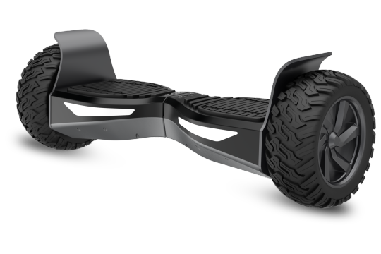
it's a intelligent mode of this transporter from 1 area to another with elastic batteries and electric motor costs. Here will we attributes the best hoverboards for 2018.
There are two wheels in the corner, and in its centre, there's a platform where both foots are placed. It functions on the gravitational force when you move your body to the front it goes ahead in the event you would like to go backward then lean little bit precisely the same for right and left direction.
Very best Self Balancing Scooters 2018
To find the top 10 hoverboards list check below or scroll down today.
Self balancing scooters was invented and started in China, but afterwards it was a massive success in usa. It had been discovered for the middle-class individuals who can not afford luxurious cars.
The principal purpose is to reduce traffic and air pollution since our humanity had made a hole in the ozone layer. So, the Chinese invented this Pollutionless automobile.
Just 1 man can travel in hoverboard and there were several devices appeared in Japan however 2014 it became famous for all of us.
The electrical hoverboard runs at the rate of 20 mph it can carry up to 220 pounds weight it typically varies weights rate depending upon their models.In 1985 it had been introduced in the film called back into the future there'll stunt arrangement for more than fifteen minutes.
There's different kinds electric scooters electric battery hoverboard where you could control the hoverboard 1 hour and ready to roll. Double wheel and hand grip rod this is also one form of electric scooter operate on precisely the identical mechanism except on one condition you may set both hands to the hand control in this situation your hand controls the whole machine.
It's a fantastic selection of transport..next ten years that the future will be a self-balancing scooter in every corner of the world'the science behind the electric bicycle is the electromagnetic induction magnetic field, electromagnetism, physics, it levitates.
How self balancing scooter operates?
Major Areas of the self balancing scooter:
Two heavy duty motors
detectors
a battery backup
double sensors( LED and infra)
chargeable port
led lighting
foot pressure pads
logic boards
eddy current
start button
Working Principle of Self Balancing Scooters
Eddy current is generated into the cheap hoverboard brakes; the wheel consists of direct current motors by default,the wheels also comprises the split sensor where the speed and rotation of the hoverboard brakes are calculated and its controlled by the speed control systems.
To be quite simple guides and monitors the angular velocity change in the unit of time.
Thus the revolutions per minute of these wheels are sent to the gyroscope. 2 gyro sensors are provided close to each of balancing scooter
There are two detectors in the logic board LED detector and infrared sensor..this detector plays a substantial part in riding the hoverboard. When you step into the pressure pads and then lean forwards it the very small plastic button infrared detector as long as the LED infrared monitors the detector beams it has a tendency to continue moving your hoverboard. If it stops detecting, it stops.
EPIKGO Sport Balance Board is among the best selling hoverboards by epikgo brand, and the top speed is 10mph, and it's water resistance and certified by IP56, and charging 3-4 hours , it is possible to ride it for an entire day. It's constructed with the incredibly powered set of motors i.e400Watt and operates in most streets conditions and composed of high durable metal. In regards to security, it has attained most top grades(UL 2272 Accredited ).
Halo rover hoverboard the newest from Los Angels that has won every child's heart and rated"EVERY KIDS DREAMED HOVERBOARD." 2018. This hoverboard comes with unique specifications that no other manufacturers has like Bluetooth sensors and mobile program to operate it. Its also (UL 2272) Certified product It's easy to carry but Bulit with exceptionally strengthen aluminum guards.
Also Check the ihawk board reviews for 2018
0 notes
Text
Self balancing Scooter or hoverboard

it's a intelligent mode of this transporter from 1 area to another with elastic batteries and electric motor costs. Here will we attributes the best hoverboards for 2018.
There are two wheels in the corner, and in its centre, there's a platform where both foots are placed. It functions on the gravitational force when you move your body to the front it goes ahead in the event you would like to go backward then lean little bit precisely the same for right and left direction.
Very best Self Balancing Scooters 2018
To find the top 10 hoverboards list check below or scroll down today.
Self balancing scooters was invented and started in China, but afterwards it was a massive success in usa. It had been discovered for the middle-class individuals who can not afford luxurious cars.
The principal purpose is to reduce traffic and air pollution since our humanity had made a hole in the ozone layer. So, the Chinese invented this Pollutionless automobile.
Just 1 man can travel in hoverboard and there were several devices appeared in Japan however 2014 it became famous for all of us.
The electrical hoverboard runs at the rate of 20 mph it can carry up to 220 pounds weight it typically varies weights rate depending upon their models.In 1985 it had been introduced in the film called back into the future there'll stunt arrangement for more than fifteen minutes.
There's different kinds electric scooters electric battery hoverboard where you could control the hoverboard 1 hour and ready to roll. Double wheel and hand grip rod this is also one form of electric scooter operate on precisely the identical mechanism except on one condition you may set both hands to the hand control in this situation your hand controls the whole machine.
It's a fantastic selection of transport..next ten years that the future will be a self-balancing scooter in every corner of the world'the science behind the electric bicycle is the electromagnetic induction magnetic field, electromagnetism, physics, it levitates.
How self balancing scooter operates?
Major Areas of the self balancing scooter:
Two heavy duty motors
detectors
a battery backup
double sensors( LED and infra)
chargeable port
led lighting
foot pressure pads
logic boards
eddy current
start button
Working Principle of Self Balancing Scooters
Eddy current is generated into the cheap hoverboard brakes; the wheel consists of direct current motors by default,the wheels also comprises the split sensor where the speed and rotation of the hoverboard brakes are calculated and its controlled by the speed control systems.
To be quite simple guides and monitors the angular velocity change in the unit of time.
Thus the revolutions per minute of these wheels are sent to the gyroscope. 2 gyro sensors are provided close to each of balancing scooter
There are two detectors in the logic board LED detector and infrared sensor..this detector plays a substantial part in riding the hoverboard. When you step into the pressure pads and then lean forwards it the very small plastic button infrared detector as long as the LED infrared monitors the detector beams it has a tendency to continue moving your hoverboard. If it stops detecting, it stops.
EPIKGO Sport Balance Board is among the best selling hoverboards by epikgo brand, and the top speed is 10mph, and it's water resistance and certified by IP56, and charging 3-4 hours , it is possible to ride it for an entire day. It's constructed with the incredibly powered set of motors i.e400Watt and operates in most streets conditions and composed of high durable metal. In regards to security, it has attained most top grades(UL 2272 Accredited ).
Halo rover hoverboard the newest from Los Angels that has won every child's heart and rated"EVERY KIDS DREAMED HOVERBOARD." 2018. This hoverboard comes with unique specifications that no other manufacturers has like Bluetooth sensors and mobile program to operate it. Its also (UL 2272) Certified product It's easy to carry but Bulit with exceptionally strengthen aluminum guards.
Also Check the ihawk board reviews for 2018
0 notes
Text

Electromagnetic braking systems use electronic and magnetic power to apply wheel brakes. Our system utilizes the concept of electromagnetism in order to achieve braking without friction. For know more information about the Electromagnetic Eddy Current Brake. Visit at BMC Motor.
#Electromagnetic Eddy Current Brake#brushless dc motors market#brushless dc motors#frameless torque motor#high efficiency brushless motor
0 notes
Text
Electromagnetic Clutches
Electromagnetic Clutches Advantages of use: » Electrically remotely actuated. » Reduced power consumption from engine. » Extended pump life. » Lower operator cost. » Simple installation. » Operator convenience/safety. » Cold weather starting. General description of electromagnetic clutches These are flange mounted, normally a two piece construction clutch typically mounted directly on to the…

View On WordPress
#AC motors#DC motors#eddy current brakes#Electromagnetic#electromagnetic brakes#Electromagnetic Clutches#Electromagnetic fields#hysteresis magnetic couplings#Magnetic Applications#magnetic brakes#magnetic particles
1 note
·
View note
Text
Characteristics of eddy current New England
Eddy Current New England in quasi impedance materials create both heat and electromagnetism forces. Solenoid heating may be done using the heat. Electrostatic forces can be employed for levitation, movement, or to provide a powerful braking effect.
Liquid Penetrant Massachusetts is a quasi substance testing procedure that employs capillary forces to detect and see surface cracks or holes. It can identify surface faults including cracks, laps, and porosity.
0 notes
Text
Engine Dyno Technique, Gen III Gasket Help, Weird AMC Engine Trivia
Chicken or Egg: Dyno Style
Peter Stanwicks; Haddam, CT: I don’t have any muscle cars or hot rods, but really admire the technology and craftsmanship. I mostly do old sports cars and boats. My most recent project was building a Bristol 100D cross-pushrod engine. What is the procedure for an engine dyno test? Is a load put on the engine gradually as the throttle is opened to wide-open throttle (WOT)? Is the load then reduced to allow the engine to gain rpm? Another way to ask the question: Is the entire dyno test done at WOT and the load varied to produce the rpm?
Steve Magnante: Interesting question, and one with a couple of answers. In the old days, dynos were manually operated and had two control levers: one connected to the carburetor and the other to the dyno to manipulate load. The results could be influenced by the operator and the technique used. Dyno operators had to be well trained or damage could result.
But today’s dynos are mostly automated and have one handle (or dial) that controls the throttle. Outfits like Superflow, Dynamic Test Systems (DTS), and Land & Sea manufacture a range of affordable dyno units, helping the practice of dyno testing and tuning spread throughout the land. Before this, dynos were the sole province of Detroit automakers and only the most well-funded professional race teams and engine shops.
During a test on a modern commercial unit, the operator generally pushes the handle from idle to full open (WOT) in a steady move that takes just a couple of seconds. From there, the handle is maxed and the computer controller takes over as long as the operator keeps the handle buried (pulling the handle back aborts the run in an emergency). To answer your question, the carburetor/EFI throttle blades are wide open throughout the test, which usually takes place over 15 to 20 seconds. Of course, without a load, revs would shoot to the moon and parts would scatter. But because the crank is attached to a power-absorption unit, it’s safely harnessed and protected from destruction. And it is the power-absorption unit that is discussed next.
Most affordable dynos found in small shops are of the water-brake variety. Here, a rotational element (affixed to the crankshaft) churns inside a stationary housing (stator). It’s quite similar to a torque converter, but with the converter held still and using water instead of ATF. The amount of drag on the crank/engine is controlled automatically by the dyno computer.
A strain gauge connected between the non-moving stator and its rigid mount determines how much torque the crankshaft is spitting out. Then, since horsepower is a mathematical equation derived from torque, the horsepower curve/chart is calculated by the dyno’s computer—as well as torque. Other sensors monitor, record, and print out information pertaining to A/F ratio, brake-specific fuel consumption, fluid temperatures, and more.
More expensive eddy-current dynos rely on an electrical current instead of water. Here, a steel rotating element (affixed to the crank) spins through an electromagnetic field. Increasing the magnetism adds load against the crank, which is then measured as torque. The eddy-current dynos are far more costly, but offer greater load-control precision. They can hold an engine within 1 or 2 rpm versus the less precise water-brake’s 5 to 10 rpm capability.
The cream of the crop is alternating-current dynos, which use (essentially) a huge AC electric motor. These dynos can measure engine output (by absorbing power), but also have the ability to reverse the situation, bully the engine, and power the crankshaft. This is useful in replicating real-world, on-track conditions where downshifting, upshifting, and coasting are part of the horsepower-delivery picture. In these modes, the rear tires of a moving car can actually “motor” the engine due to vehicle momentum. While water-brake and eddy-current dynos are passive, AC dynos can be active and copy this sort of condition.
To further answer your question about the relationship between the engine and dyno during testing, every dyno is calibrated to keep a firm grip on the crankshaft as they arm-wrestle each other. If this grip was iron-tight, the engine wouldn’t be able to accelerate and no data would be gathered. So dyno power-absorption units must be set to allow the engine to creep up to the preset redline. This is called the acceleration rate and is generally measured in rpm per second. Most commercial dynos let the engine rpm rise at the rate of 300 to 600 rpm per second, but this can be manipulated. Hopefully, this sheds some light on the dyno situation for you. As for your Bristol, there’s no law that says every car has to have a V8 to be quick and fun.
Hardly bigger than a 5-pound coffee can, the power-absorption unit—aka water-brake—is exactly that. Fairly inexpensive, water-brake test stands brought dyno testing to the common man.
Reader Peter Stanwick’s Bristol mill has hemispherical chambers, but every other pushrod is horizontal! You gotta Google “1938 BMW 328 engine” to see how it works!
In-Car, LS Cam-Swap Advice
Dave Conant; via CarCraft.com: I have an LS3 in a 1969 Nova, and I’m thinking about swapping cams. I really don’t want to go through the hassle of pulling the engine and want to do the swap in the car. I’m worried about the harmonic damper and front cover. I know Gen III engines don’t use alignment pins or dowels anywhere but the heads and transmission. How do I install the front cover so the seal is centered before the damper goes back on?
Steve Magnante: Being a total, clean-sheet design, the Gen III small-block gave Chevrolet engineers a rare opportunity to eliminate some to the previous small- and big-block’s more frustrating traits. Back in 1955 when Harry Barr, Ed Cole, and the guys whipped up the original 265ci mouse V8, many competing American V8 engine-block designs featured bulk-adding, deep-skirt crankcase extensions. By slashing the block down to the crankcase centerline, more than 50 pounds of dead weight was eliminated from the block alone. Then by making the intake manifold do double duty as the tappet valley cover, even more weight was saved.
But the resulting oil pan rail/timing cover was a sealing nightmare. With its dual cork side gaskets and semicircle end seals (one-piece by 1986), achieving a leak-free assembly was rare. By contrast, the Gen III takes sealing to a whole new level. All mating surfaces are flat and uninterrupted, and a new wave of gaskets—with integral silicone beads and foolproof, anti-crush shims—are the norm. They’re easy to seal up and rarely leak a drop of fluid.
That said, your observation regarding the Gen III’s lack of front cover-alignment pins is correct. The goal is to position the timing cover so there is equal distance all around the crank snout and seal before tightening it down. It’s not a big deal—if the engine is on a stand and out of the car. There, you can eyeball things and get by. But with the engine in the car, unless you’re a giraffe, it’s about impossible.
Predicting this hassle, GM service departments were issued special tools and fixtures to aid in-car servicing. Tool subcontractor Kent Moore Tools offers what you need. Get the front and rear cover-alignment tool set (PN J41476) and harmonic-damper installation kit (PN J41665). These tools and fixtures are easy to use and yield a leak-free job.
Speaking of yield, don’t forget that the factory damper bolt; like all fasteners on the Gen III V8, it’s a one-time-use, torque-to-yield item. The factory guide says to use the Kent Moore damper-installation tool to seat the damper after your cam swap. Then it says to take the old bolt and use it to crank down the damper to 240 ft-lb. Then you’re supposed to remove the old bolt and replace it with a fresh one. This bolt gets tightened to 37 ft-lb and a second pass with a rotational-angle-type torque wrench spins it another 140 degrees past the 37–ft-lb mark. Doing all of this in the car is a hassle. You can skip it by switching to an old-fashioned bolt from ARP (PN 234-2503). It’s even reusable!
More Info ARP Fasteners; 800/826-3045; ARP-bolts.com Kent Moore Tools; 888/220-8350; ToolSource.com
Some AMC Weirdness
Steve Magnante: Nobody asked for this one, but the aluminum-block construction seen in this month’s Bristol and LS3 engine discussions reminded me of some cool AMC engine history. Did you know AMC offered an optional aluminum-block, six-cylinder engine in 1961–1964? Manufactured for AMC by the Doehler-Jarvis division of the National Lead Company, it was essentially an aluminum-block version of Rambler’s iron 195.6ci OHV six. The alloy mill saved 50 pounds and was only offered in the midsize Rambler Classic—never the compact American (bummer).
AMC also toyed with an all-aluminum V8 that never saw mass production. Based on Rambler’s first 250, 287, 327 V8 family (1956–1967), only prototypes were made. Alcoa (the Aluminum Company of America) was in charge of casting the T356 sandcast blocks and heads. I discovered a 327ci version (in parts) in the hands of hardcore Rambler historian and collector Larry Daum.
One final bit of AMC engine trivia concerns the 1983 2.5L Jeep inline-four-cylinder engine. A replacement for the Pontiac-sourced 2.5 four used previously, the new 2.5 was expanded into the 4.0L inline-six in 1988. At AMC’s Kenosha, Wisconsin, engine plant, the four- and six-cylinder heads were machined on the same line for efficiency. But since the four-banger head was shorter than the six, it was cast with a dummy extension that allowed it to fit onto the same drilling, decking, tapping, and so on stations as the longer 4.0 head. After the final machining operation was completed, the stub was simply sawed off. The circular shaved area that accepts the thermostat housing on the 2.5 is where the stub used to exist. If only engines could talk—the stories they’d tell!
More than 100,000 aluminum-block sixes were installed in early 1960s Rambler Classics. I found this one in a Massachusetts boneyard.
Rambler’s version of an LS1, this lightweight 327 was produced in 1957 by Alcoa as a feasibility study.
The post Engine Dyno Technique, Gen III Gasket Help, Weird AMC Engine Trivia appeared first on Hot Rod Network.
from Hot Rod Network http://www.hotrod.com/articles/engine-dyno-technique-gen-iii-gasket-help-weird-amc-engine-trivia/ via IFTTT
0 notes