#centerline woodworking
Explore tagged Tumblr posts
Text
Master Your Craft with the Help of Spirit Levels - Your Ultimate Guide
Are you looking for the right tool to help you become a master craftsman? The spirit level is one of the most popular and versatile tools that can help you take your craft to the next level. This guide will provide you with everything you need to know about how to select the right spirit level and make the most of it while crafting.
What is a Spirit Level?
A spirit level is a tool typically used by woodworkers, craftsmen and home renovators to accurately measure the degree of tilt in two dimensions. Spirit levels usually have at least one bubble tube containing a liquid that helps indicate the angle. The spirit level uses a transverse gravity gradient to display the tilt.
How Do They Work?
When a spirit level is held horizontally, the liquid in the bubble tube will move to the middle of the tube. This is because liquid is always pulled towards the bottom of its container due to the force of gravity. When the spirit level is turned, the liquid will move towards the side. The degree of tilt can then be determined by looking at where the bubble is compared to the centerline of the tube.
What Features Should I Look For in a Spirit Level?
High-quality materials: The quality of the materials used in a spirit level is important to ensure accuracy and durability. Look for aluminum or steel spirit levels that won’t warp or corrode.
Accurate measurements: Make sure the spirit level has markings that accurately measure the angle of tilt.
Shock resistant level vials: This ensures that the level vials won’t be damaged by drops or knocks when you are using the spirit level in difficult conditions.
Ergonomic design: Look for a spirit level with a comfortable grip and raised edges that make it easy to hold.
Non-slip base: Make sure the spirit level has a non-slip base that prevents it from slipping when you are using it.
Using a Spirit Level for Crafts
Once you have found a good-quality spirit level, you are ready to start improving your craft. Here are some tips for getting the most out of your spirit level:
Measure angles: Use the spirit level to help you accurately measure angles while working with wood or other materials.
Check walls: Use the spirit level to check whether walls in your home are perfectly vertical or not.
Laser points: Spirit levels come with laser points that make it easier to check whether two points are aligned or not.
Mark off points: Use the spirit level to quickly and accurately mark off points for drilling or cutting.
By using a spirit level, you will be able to craft with greater precision and accuracy than ever before. So if you want to take your craft to the next level, consider investing in a spirit level and you will soon be making perfect creations.
Questions and Answers
Q: What type of tool is a spirit level?
A: A spirit level is a tool typically used by woodworkers, craftsmen and home renovators to accurately measure the degree of tilt in two dimensions. Spirit levels usually have at least one bubble tube containing a liquid that helps indicate the angle.
Q: What should I look for in a spirit level?
A: Look for a spirit level that is made from high-quality materials, has accurate measurements, is shock-resistant, has an ergonomic design, and has a non-slip base.
Q: How can I use a spirit level for crafts?
A: You can use a spirit level to measure angles, check walls, use laser points, and mark off points for drilling or cutting.
0 notes
Text

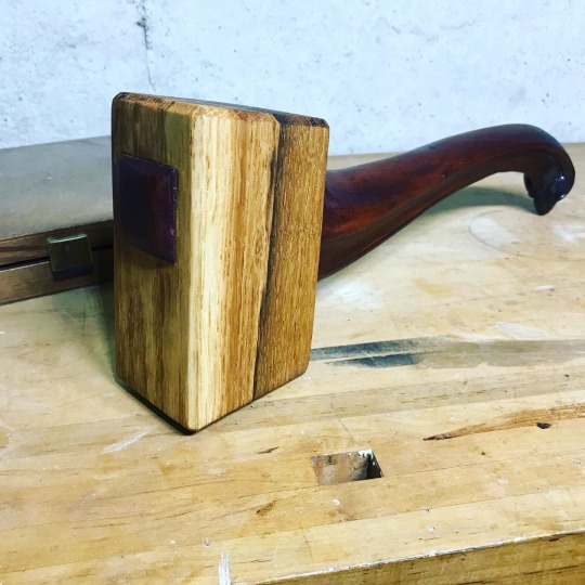
Wooden mallet from an oak crane mat and an old chair leg.
0 notes
Text
The advantages of double fisting
There’s a stunt I’ve started doing when I teach in-person classes about Japanese saws. (In-person classes. Remember that?) For this demonstration, I ask for a volunteer, and I specifically ask for a volunteer who doesn’t consider them very good with a Japanese saw. I put a board in a vise, strike a line, and ask the volunteer to saw to that line. Almost always, the saw cut starts well, but then there’s a drift away from the line.
Then I strike a second line, and ask them to make one modification to their technique, which is to start the cut, and then to hold the saw with two hands. Almost always, they nail the cut. You can see that in the photo below.

One clear difference between Japanese and western saws that is often overlooked is the handle. Japanese saws have a long, straight handle that allows them to be used either one-handed or two-handed. The vast majority of the time, I use one hand for a saw cut, with the other hand holding my workpiece. I’ve found it best to hold the handle at the very end, because any error because of minor movements of my hand will be minimized at where the saw is cutting, as opposed to if I was choking up on the handle.

Sometimes, however, I’ll be making a cut, usually a longer cut, where I really want to be as accurate as possible. In these cases, I’ll use a holdfast or clamp to hold the workpiece in place, start the cut one-handed, and switch to two hands as soon as I can. This by itself will make the cut more accurate.

Why does this work? The advantage of a two-handed stance is that you line up the center of your body with the cut almost automatically, which by itself makes making an accurate cut easier.
Some years ago, there was a lot of discussion regarding being right or left-eyed, and how this affected your sawing if you were right or left-handed. When sawing with one hand, almost all woodworkers will line up their dominant eye with the cut, which is inherently off-balance. And if you are right-handed but left-eyed, or the other way around, that made things even more difficult. This takes the whole right/left eyed issue out of the equation.
In this photo, you can see how I line up just my right eye with the saw when sawing one-handed. (I don’t ever saw a board this way in my shop, but it was the only way I could get the right camera angle.)

When I saw with both hands, the centerline of my body lines up with the saw and the cut, and I’m using both eyes to see what I’m doing.

This also works if you are sawing a board using sawhorses. It looks like my head is tilted slightly in this picture, but that’s because my body is slightly off-center because I have my left foot up on the sawhorse. The cut line is still in line with the center of my body, and I’m using both eyes to look at the cut.

I’ve done the one-handed/two-handed demonstration enough times now that I’m confident it will work every time. I’m convinced it’s the lining up of the centerline of the body with the cut that almost makes it difficult to saw off-line.
Again, this is something that I don’t do most of the time. But for longer cuts, this is a technique I’ll use. If you’re having trouble sawing to the line, I’d highly recommend giving it a try.
20 notes
·
View notes
Text
20 Best Circular Saw Reviews [ 2021 Buyers Guide ]
This Milwaukee worm pressure noticed closes our listing these days, however it nonetheless ranks a few of the first-class. The saw comes in heavier at 15lbs, however that doesn’t suggest that it is not consumer-friendly. So sure, it's far a bit heavier than different saws that weigh round 11lbs, but you received’t enjoy plenty exhaustion while working with it.
This noticed is manufactured from magnesium construction that continues it robust for long. Also, you get a hardened steel computer virus gearing that gives most toque for coping with even the toughest tasks. There is a 15amp motor that gives pinnacle speeds of four,400RPM to help you along with your workpieces. We noticed that the motor doesn’t bog down, even when managing the heavy masses.
Along with that, you enjoy a heavy-responsibility composite shoe that doesn’t bend, warp or kick up a burr whilst running. You will have an easy time operating with this unit, specifically since it comes with an different oil website online glass and an instantly gauge present day oil level.
By the manner, we observed the lower guard became barely loose, which may not be appropriate for an extended-hour job. One element to note about the computer virus force saw is that it comes with an introduced torque and weight. Therefore, they're the best select for slicing stacks of lumber and knotted wooden.

Its tremendous electricity permits the saw no longer best to reduce through knotty woods but additionally for plunge cuts. Furthermore, bug pressure saws will usually be utilized in woodworking and construction fields. They don’t possess a slender profile for the reason that centerline of the motor is parallel to the plane of the blade. In different phrases, it implies that worm pressure saws are perfect to be used in restricted spaces.
The huge gear teeth of worm pressure saws also allow them to have a more load-wearing ability. With a unique gearing gadget, the exceptional bug power round saw can produce more torque than a fashionable circular saw. And this is what you want whilst your woodworking jobs require a touch more energy.
However, those saws are first-rate desirable to professionals and severe DIYers. And don’t expect it because the equal sidewinder-style models you might be thinking.
Among the masses of exceptional ones, this computer virus power circular saw reviews will really assist you to find out the satisfactory one which applicable your interest and assignment. Let’s begin scrolling beneath to read our sincere buying guide, checking out method and our editor’s pick out decided on computer virus pressure noticed critiques.
In the last century, a man from Louisiana first invented the malicious program drive noticed. The intention of that invention changed into to help workers who have been having an trouble whilst cutting down sugar cane. Only a saw that got here with higher torque would have saved them, and this tool clearly came to ease their work at that time.
This kind of saw has a blade that takes area on the front aspect of the motor. Therefore, the blade role over there permits the threaded computer virus pressure to move right down to the shaft. The bug’s thread gears are the most critical part that connects with the blade arbor in the front of the motor. The above placement and functionalities permit the blade benefit better torque abilties, enabling it to reduce tough and dense materials.
1 note
·
View note
Photo

Blueboi made from Green Ash (fraxinus pennsylvanica) with full draw specs of about 40# @ 27". A gentle deflex/recurve profile, centerline at the top of the handle (asym and a bit of positive tiller), a heat treated belly, a whipped hemp cordage handle, some blue paint on the back, black ram horn tips wrapped with sinew, and walnut oil/beeswax sealant. . . . . . . #bushcraft #wildernessskills #primitiveskills #traditionalskills #selfreliance #selftaught #artisan #woodworking #handmade #handcrafted #handtools #woodcraft #naturalmaterials #bowmaking #bowmaker #bowyer #archery #traditionalarchery #traditionalbowyer #primitivearchery #primitivebowyer #bowsnarrows #longbow #selfbow #recurvebow #custombow #woodenbow #handmadebow #woodenarrows #handmadearrows https://www.instagram.com/p/B85CjPSD9AO/?igshid=bszj6z5mbwz1
#bushcraft#wildernessskills#primitiveskills#traditionalskills#selfreliance#selftaught#artisan#woodworking#handmade#handcrafted#handtools#woodcraft#naturalmaterials#bowmaking#bowmaker#bowyer#archery#traditionalarchery#traditionalbowyer#primitivearchery#primitivebowyer#bowsnarrows#longbow#selfbow#recurvebow#custombow#woodenbow#handmadebow#woodenarrows#handmadearrows
26 notes
·
View notes
Photo

While I’m waiting in between stages of 2 projects I figured I’d whip together a scrap cedar chisel holder I’ve had in my head for like 2 years. These poor chisels have been hanging in a cardboard box since I got them. They’re too nice for that, so it’s time for a nicer and more functional home on the hand tool cabinet. Second picture is showing how awesome the @woodpeckers_tools DelVesquare is (again). I’m using the offset base to mark the centerline in this 3/4” cedar board so I can resaw it. Super handy, no measuring. 👍🏻👍🏻 . . . . . . . . #wood #woodwork #woodworker #woodworking #finewoodworking #maker #cedar #handmade #handcrafted #maker #diy #doityourself #accessories #DelVe #summer #chisel #fancy #rustic #display #thejawnshop https://www.instagram.com/p/BncRSTggBRT/?utm_source=ig_tumblr_share&igshid=7wvf21lmpzc5
#wood#woodwork#woodworker#woodworking#finewoodworking#maker#cedar#handmade#handcrafted#diy#doityourself#accessories#delve#summer#chisel#fancy#rustic#display#thejawnshop
3 notes
·
View notes
Text
How to Build a Garden Gate
The white picket fence may be what we all dream of, but who says you need the whole thing? A crisp white garden gate provides the same feel. Install it at the head of a path, leading to a garden or your front door, and flank the posts with tall plantings. Though there are more styles than we care to count, choosing one could be as easy as researching historic designs. In fact, it may be necessary; some localities enforce historical accuracy, which is how we landed on this design in Bellport, New York. Luckily, This Old House senior technical editor Mark Powers’s approach applies to a variety of styles. Follow along to see how to build a gate that won’t get you pilloried by the locals.
Shown: Devonshire Twisted Ring Gate Latch, about $49, and 16-inch Old Fashioned Heavy Reversible strap hinges, about $110 a pair; Walpole Woodworkers
You're reading: How to Build a Garden Gate
How to Build a Garden Gate Overview

Illustration by Gregory Nemec
Day-to-day timeline
PREP DAY: Install the posts (Steps 1 & 2).
SATURDAY: Cut the parts and build the gate (Steps 3-11).
SUNDAY: Attach the hardware and install the gate and post caps (Steps 12-16).
Size your gate to the width of your path, allowing room for the postholes on either side. Our gate is unusually wide, at four feet, but you can easily adapt the cut list to a narrower size by adjusting the width of the horizontal pieces.
Garden Gate Cut List
Stiles: 2 @ 35 inches
Top rail: 1 @ 47½ inches
Bottom rail: 1 @ 42½ inches
Crosspiece: 1; trace to fit
Filler block: Rip 1×3 to fit between pales; ours was 2 inches
Rip 2 ½-inch-wide stiles from 5/4 decking.
1×5 cedar brace: 1 @ rip to 4 inches wide, length cut to fit
Using a circular saw, rip edges at opposing 30-degree angles.
1×3 cedar pale: 4 @ 38 inches
1×3 cedar pale: 4 @ 39 inches
1×3 cedar pale: 2 @ 40 inches
1×3 cedar pale: 1 @ 41 inches
Shape the tips of the pales, then cut them to length.
Apron board: Rip one to 4 inches wide by 47½ inches long.
Apron strip: Rip one to 1½ inches wide by 47½ inches long.
Using a circular saw set to a 5-degree bevel, rip a 5/4 deck board into two pieces to create both the apron board and strip.
6×6 treated post: Cut two to the desired height while maintaining a portion that’s at least one-third the total height of the post that will be buried. For our design, we used 6-foot posts and left 4 feet above ground.
Step 1: Dig the Postholes

Photo by Kolin Smith
Use stakes and a mason line to plot two holes evenly on either side of the walkway so that, center to center, they create a line perpendicular to the path. Dig each hole 6 inches below the frost line or far enough to sink one-third of a post, whichever is deeper. Make the diameter three times the size of the post.
Step 2: Wrap and Set the Posts
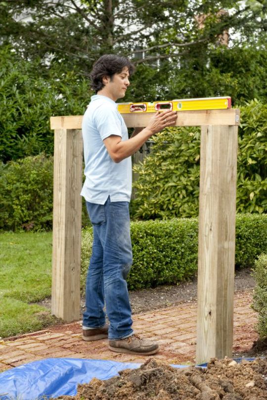
Photo by Kolin Smith
To prevent rot, wrap the sections of post to be buried with self-adhesive flashing, from near the bottom to just below ground level. Use the posts to tamp 6 inches of drainage stone into their holes; place them, and add another few inches of stone to hold them plumb. Pour dry concrete mix into one of the holes, filling it to just below the flashing. Add water until the mix is saturated, and stir it with a stick. Before setting the second post, use a board and a level to make sure the posts are the same height. Hold the board up to their faces to make sure they’re not twisted. Allow the posts to sit undisturbed overnight, then sand and prime them.
Read more: Eight Eggplant Recipes You’ll Love
Step 3: Assemble the Frame of the Gate

Photo by Kolin Smith
Rip the top and bottom rails to 4 inches and the stiles to 2½ inches. Cut the top rail 1 inch shorter than the span between the posts to get a ½-inch gap on each side. Cut the other three pieces to length, then prime all four. Once dry, align the stiles beneath the top rail, like legs. Drive 3-inch stainless-steel screws at an angle through the edges and up into the top rail. Fit the bottom rail between the stiles 5 inches from their lower ends. Drive screws through its edges and into the stiles, as shown.
Step 4: Mark the Crosspiece

Photo by Kolin Smith
Rip a 2½-inch-wide crosspiece from a 6-foot board and prime it. Mark a centerline at each end of the crosspiece, slip it under the frame running from the latch location to the lower opposite corner, and position the centerlines at the corners. Now simply trace the inside of each corner on the crosspiece, as shown.
Step 5: Cut the Crosspiece

Photo by Kolin Smith
Using the circular saw, cut along the corner marks. Prime the exposed ends. Fit the crosspiece into the frame and use a drill/driver to send 3-inch stainless-steel screws through its edges and into the frame.
Step 6: Bevel the Brace to Make the Gate’s Trim
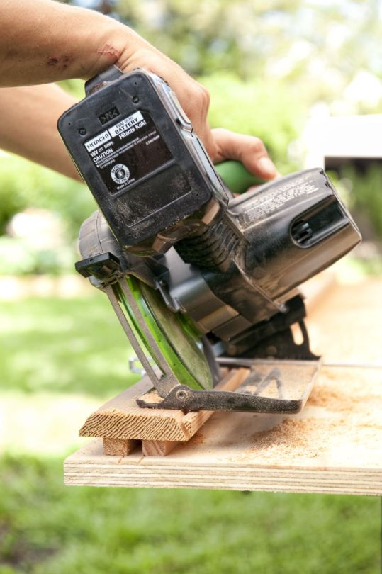
Photo by Kolin Smith
Set the circular saw to a 30-degree bevel and rip one edge of the brace. Now set the saw’s fence to 4 inches and rip the other edge at an opposing 30-degree bevel, as shown, to make the wider face 4 inches. Prime the brace.
Step 7: Install the Apron
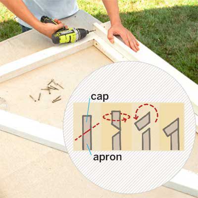
Photo by Kolin Smith
Cut the apron to the width of the frame. Set the circular-saw blade to 5 degrees and rip a 1½-inch strip off one edge. This cut produces the beveled apron and a slanted cap for it. Prime both. Position the apron on the front of the frame, flush with the bottom of the stiles, and drive 1 5/8-inch stainless-steel trim-head screws through it and into the frame. Position the cap with its beveled edge against the frame and its narrow edge against the apron’s bevel, as in the diagram at right. Screw it into the apron.
Step 8: Create the Pales
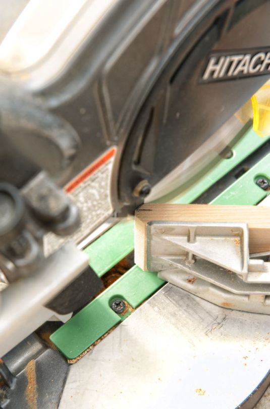
Photo by Kolin Smith
Cut the face bevels. You’ll bevel all four sides of the tips to shape the gate’s vertical slats, or pales. At the top, make a hash mark ¼ inch in from each edge. Set the miter-saw blade to 45 degrees and place a pale on edge against the fence. Align the blade with the mark and cut the bevel; flip the board and do the same on the opposite edge, as shown. Cut all the pales the same way.
Step 9: Cut the Edge Bevels
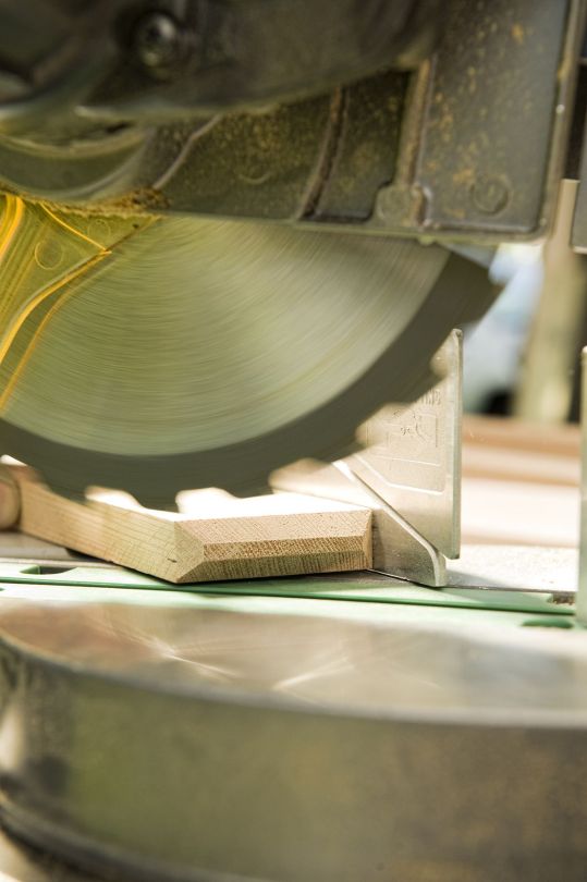
Photo by Kolin Smith
Lay each board flat on the saw. Keep the blade at 45 degrees, line it up with the point where the bevel meets the edge, and clip the corners, as shown. Once you’ve shaped all the tips, cut the pales to height by beveling the bottoms at 5 degrees, to match up with the slanted cap of the apron. Prime the pales.
TOH Tip: Use a combination square with the blade depth set to ¼ inch to quickly make accurate cut marks.
Step 10: Install the Pales
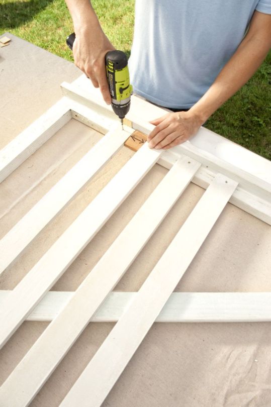
Photo by Kolin Smith
Center the tallest pale on the frame, with the bevel at the bottom mirroring that of the apron cap but not quite touching it. Leaving a tiny gap is critical to staving off end-grain rot; a paint stick makes a perfect spacer. Using a drill/driver and 1 5/8-inch stainless-steel trim-head screws, attach the center pale to the top and bottom rails. Then take two of the shortest pales and attach them flush at either end of the frame. Evenly space the remaining pales in descending order between the center pale and the ends. Cut a block equal to the width between pales and use it as a spacer. Attach the pales. Finally, screw a filler block between the first two pales for the latch.
Read more: Possum Security
Step 11: Finish the Gate: Secure the Brace
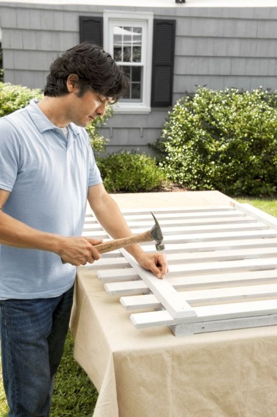
Photo by Kolin Smith
Lay the brace across the pales, beveled-side up, in line with the top rail. Use a hammer and 1 5/8-inch stainless-steel siding nails to attach it. Next, paint the gate, posts, and caps.
Step 12: Add and Secure the Post Caps

Photo by Kolin Smith
Using a caulk gun, apply adhesive to the post caps and press them in place on top of each post. If there’s any play, be sure to center the caps.
Step 13: Shim and Level the Gate in Place

Photo by Kolin Smith
Prop up the gate on scrap blocks between the posts, at least 2 inches above the highest point in its path, apron-side out. Shim it level, and use a level to check your work. Be sure to keep an even gap on each side. Center the gate on the posts, then shim it in place between them.
Step 14: Position the Hinges
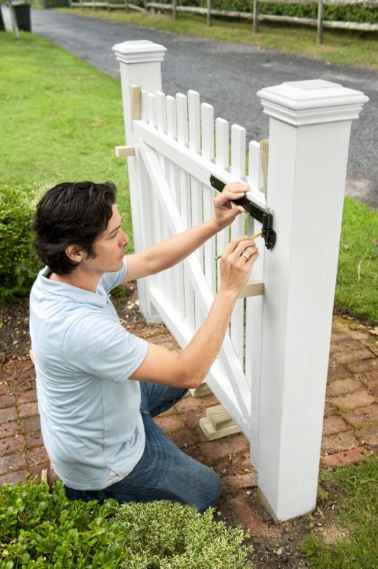
Photo by Kolin Smith
Hold the strap hinges and their lower pin cups up to the back of the gate, in line with the top and bottom rails. Mark their screw holes on the gate and post.
Step 15: Attach the Hinges

Photo by Kolin Smith
Lay the gate flat, and align the strap hinges with their marks. Drill pilot holes into the frame, and screw the straps in place with their included fasteners. Install the lower pin cups on the post and slip the pins into them to hang the gate. Check to see that it stays level through its swing; if it does, install the upper pin cups to lock it in place.
Step 16: Add the Latch and Stop

Photo by Kolin Smith
With the gate closed, position the stop on the post below the brace. Drill pilot holes and screw it to the post. Working from the back, position the latch assembly on the top rail and post, mark their hole locations, and drill a hole for the spindle and pilot holes for the fasteners. Finish by mounting the latch and corresponding hardware.
Source: https://livingcorner.com.au Category: Garden
source https://livingcorner.com.au/how-to-build-a-garden-gate/
0 notes
Photo

Centerline...for installing pulls. Pulls were one more thing the maker decided not to do 🤷🏼♂️The drawer still needs more work, but it’s better already. The pulls will make easier to judge when I’ve hit “enough”. . . . . . #fixingotherpeopleswork #woodwork #woodworking #whisperworkshop #scrubbing #scrubplane #bridgecitytools #bridgecitytoolworks
#bridgecitytoolworks#whisperworkshop#scrubbing#bridgecitytools#scrubplane#fixingotherpeopleswork#woodworking#woodwork
2 notes
·
View notes
Photo

The top pivots for the french doors I'm finishing up are simply a split pivot assembly with the receiving piece mortised into the top of the door. It's a simple piece, but it has to be plumb and in the same centerline as the spring pivot on the bottom of the door....so,.... time to bust out the @incra_tools tiny-t. Perfect for a situation such as this. I should have included the instruction pdf for these hinges, so everyone could get a good laugh. But at the end if the day, I've got a new skill so that's always cool. #knotty_woodcraft #makehomematter #pantrydoor #traditionaldecor #architectural #architecturalsalvage #salvage #antique #repurposed #door #port #porte #porta #homedecor #diy #interiordesign #renovation #kitchenmakeover #doorsofinstagram #woodwork #woodworker #maker #woodfinish #kitchendesign #shaker #frenchdoors #pocketdoors #double doors #slidingdoors (at Knotty WoodCraft) https://www.instagram.com/p/CByyREMj0qk/?igshid=100y99riyqzra
#knotty_woodcraft#makehomematter#pantrydoor#traditionaldecor#architectural#architecturalsalvage#salvage#antique#repurposed#door#port#porte#porta#homedecor#diy#interiordesign#renovation#kitchenmakeover#doorsofinstagram#woodwork#woodworker#maker#woodfinish#kitchendesign#shaker#frenchdoors#pocketdoors#double#slidingdoors
0 notes
Photo

youtube
0 notes
Text
On the Eave of Construction (II)
With weather remaining endlessly cold, my shop remains under that 40˚F threshold, a mark which I have decided is my cut off for working in there. I’ve been continuing on therefore, with my work at home to draw a certain type of Japanese residential roof, with an aim to cementing my knowledge of how to learn RhinoCad and work out some long-standing carpentry drawing issues which I couldn’t resolve with the previous drawing software.
I’ve put a lot of hours in, and things have been going well generally with the drawing work, at least as far as the CAD aspect is concerned. Essentially, I find that one has to flail away for a certain amount of time, have certain things not work out for some reason or another, and then try a ‘plan b’ and do it all again, and probably again, until eventually you can produce what you want. By one’s own mistakes in modeling, one learns better ways to model.
The reason for this is that with many given tasks in Rhino, there is more than one way to do it. Certain habit patterns in how I go about modeling parts I bring over from sketchup prove to not work so well sometimes in Rhino. In SketchUp you produce solids a lot of the time and then push, pull and intersect them to obtain the finished part you want. In Rhino, one can do all those same sort of techniques, but they may lead to a part which is a collection of faces that will not weld together to make a solid or some such outcome.
As an example to show the variety of potential approaches to a given objective there is the task of ‘creating a surface’, one of the most basic in modeling:
One could opt to draw 4 lines to produce the outline of the surface, then join them together with a separate command, then patch that outline with a surface.
Or, one could use the rectangle tool to produce the outline, then patch.
Or, one could draw the rectangle with a ‘polyline’ tool and then patch.
Or, one could use the ‘surface’ tool and in one move it’s done.
One could alternatively have previously created a cube, from which one can extract the desired surface, or copy that surface, or explode the cube and subtract everything you don’t need to obtain the surface you want.
One can take a set of lines comprising the surface one wants to model and then use a tool to loft a surface over that outline.
One can take the lines comprising the surface and then use a tool called ‘curve network’ to create the surface.
One could take a larger surface and then use a ‘wire cut’ tool to slice out the portion of surface in the shape desired.
I could go on as the above list is hardly exhaustive, but I’m sure the above list is enough. it’s the same for a lot of modeling tasks, with various ways to approach a thing presenting themselves. And when you are new at it there is a tendency to stick with a the one tool you got a mental grasp on, and use that exclusively, until you find one time it isn’t working for some reason. And thus you must learn other ways to do the task, and eventually one comes to understand why one chooses one tool over another to get a certain job done efficiently and well. It’s no different than woodworking really, save for the fact that the drawing work is virtual.
As a concrete example, here I’ll show a curved hip rafter. In cases like this one, where the curve is not of continuous radius, the ‘backed’ top of a curved hip has a shape which changes shape as it moves along. Thus the surfaces of the backed cut on each side are twisted planes:
This kind of twisted surface is a modeling task which was all but hopeless in SketchUp. In Rhino, there are several ways to do it. In the above I used a tool which produced quite a busy surface, but it was mathematically precise.
Later, working on a similar task on the ‘field’ hip rafter, I was able to obtain the same result with a much less busy surface, which is certainly easier to look at:
I’m very much at the early learning stage with some of these tools, so a lot of stumbles still lay ahead I’m sure.
The problem of learning which tool to use and why, is one aspect that has been another. A second point of struggle relates to the layout manuals which I use. My favorite ones are by Togashi, and they are certainly comprehensive. I thought they were essentially flawless, however I have recently discovered that he makes mistakes too.
All of my drawings for roofs and such are performed much as if I were doing the task in my shop- sketching first in 2D to produce the required shapes and then using those shapes as templates to make the parts. Here’s one of the developed views I sketched of this roof model:
Towards the bottom right is where one projects lines from the view of the eave timber build-up over to the hip rafter:
I followed Togashi’s methods, however because I am able to create the parts afterwards as 3D solids and then superimpose those solids back into the 2D drawing portion, I am able to check whether the 2D method is producing parts which are shaped and positioned correctly. And that’s where I found problems with Togashi’s book:
It’s a problem I actually discovered previously and had forgotten about. As you can see I do scribble notes in pencil on the textbook to keep track of things like this.
His mistake in this case is to project points over rom one view, which are of planes along the centerline of a part, then then reflect them in a secondary view but on the wrong line of reflection. If you look at the above sketch of drawing the ‘kera-kubi’ hip nose treatment, you can see that where he has marked point ‘e’ is where he reflects a line showing the front face miter from the eave’s kaya-oi timber – but the line he is reflecting the projection upon is the line for the face of the hip rafter, not its centerline.
The consequence of the above mistake would be to cut the angled receiving notch on the end of the hip rafter, right at the point of the miter, too far uphill. The kaya-oi would bind in that location, as the error in line position is about 4.5mm. It’s not as if he would be wanting to make that sort of mistake, would he? Not generally an objective in Japanese pursuits, as far as I have noticed.
I’m not expecting readers here to grok exactly what I am talking about – just to state that there is a problem in the text that I was initially in some disbelief about and had to overcome. And it is not just that page, as he repeats the same problem on other drawings, and I have discovered other minor mistakes besides.
And I’m not trying to run the guy down either – I esteem his work greatly and I’m a little shocked to find any mistakes in it as it is that good otherwise. I think my main point is that having the ability to construct parts in 3D solids off of 2D, and back-check them is a truly wonderful thing. I think that if you are only drawing in 2D all the time, with the myriad of lines to stare at it is only a matter of time before even the most experienced folks get a little mix up here and there.
Anyway, I have made some modest progress after a bunch more struggle. Here’s a view of the eave from underneath with the eave build up complete and rafters in place:
A view from the top side shows the curved field rafters getting put in, and gives a look of the field hip rafter:
The fact that the field rafters are curved down, or sagged (called ‘tarumi’), means there are some complications in the production of the field hip upper lines, as one must account for both the cure in the field common rafter, and the fact that the rafters travel along an eave edge which also curves up at the end.
I had made the field hip rafter deeper in section in the lower portion so it could sister against the decorative hip rafter below. However, after I had the parts together and could take a look, I could see room for improvement.
So, I started those parts again, and this was the result:
0 notes
Text

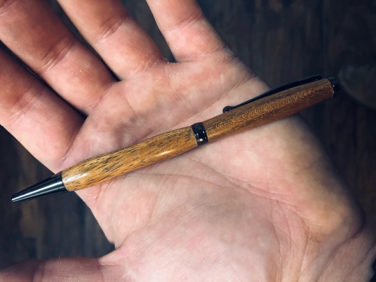
Another spalted pear pen and a couple Brazilian walnut pens. Very happy!
0 notes
Photo
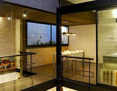
PH EL SALVADOR by Leonardo Guido Militello
DESCRIPTIVE MEMORY From the beginning of the project we understood the intrinsic qualities associated with this piece of urban fabric. We here deal with a rectangular space with measures that do not exceed 7.50 m x 12.00 m located practically in the heart of the square. This is a dwelling unit of the type of the row houses in the city of Buenos Aires. At the beginning of the last century it was common to build small houses with the conceptual characteristics of the “sausage house” multiplied for the depth of an urban lot. The project then rose as a challenge to customer demands whose programmatic needs far exceeded the possibilities offered by the nature of the terrain. We also had to be aware of the constraints brought by the responsibility of reforming a historic site that was protected by the law of the city of Buenos Aires. Limited to four workstations divided by only four walls, and conditioned by the small floor area, the premise of creating an interior courtyard became the alma mater of the project, following which we organized the housing, ordered the other spaces vertically upward reaching for air, light, and private visual, finishing it off with a pool deck. The decision on the choice and use of materials reflects the same search for each space to place it in the courtyard, in a complete and honest way, creating a glazed inner skin and a solid outer skin, resulting in either both its materiality and its spatial proportions and the idea of a pavilion floor, rather than a traditional house. Taken to the extreme, the intention was one of generating an ethereal skin-core into the courtyard of the house, and searching for a structural, tectonic and construction that would lead us to the idea of "disappearing" the structure and thus achieve a certain voltage determined by weightlessness based on the idea of a "floating pool" over living spaces. This idea was decisive along with that of the use of a mixed structure, with iron columns to continue the centerline of the woodwork, which is clearly opposed to the concrete volumes of marked visual presence. The search for constructive thinking, of an architecture of noble materials, and of the use of reinforced concrete, iron and glass panels, was complemented by the decision to use refractory bricks as the sole material for partitions, in view of achieving the desired aesthetic and insulation conditions. In turn we also reused elements of the pre-existing dwelling unit which refers us to the original spirit of the property, which combined with the proposed contemporary design, constitute an added value to the project. Regarding the links between elements, it is also interesting to look at this house. Since the refractory brick wall in the subtle touch on the existing wall (in line with this concrete column that supports the pool) the subtlety of the smithy of its columns in relation to the crystals, to frameless doors verticality to offer certain environments, everything makes a set of simple but delicate analysis in its composition. The project was always dominated by the constant search for natural light, but it was a search which served to form the crystal clear idea of weightlessness that the volume of concrete gave the space. This element ends by sewing the project clearly always looking for a dynamic cut prefixed to static symmetry structured plant. The movement of the housing is closely related to the courtyard and its visual crossing it vertically and spiraled from the PB, to 1P and finally to the roof. Both from the circulation and from each room of the house can see the true essence of vernacular courtyard. The visuals to the corridor are screened by a "cushion plant" provided by planters, thanks to which provides more depth to the dividing wall on a large scale. The skylight gives the only light that is controlled, illuminating the brick wall that frames the movement of the two levels. The program is reversed to what is traditionally understood as private and public space as a result of understanding the character of space to live during both day and night, creating a provision that goes private in the ground floor to the public on first floor, looking for something tall, light and visual. Description The ground floor contains two bedrooms en suite and a nearly symmetric entrance hall whose functionality can also be an office / expansion into the courtyard, which is the result of an interstitial space between the two functional suites. The floor, which is certainly where public program seeks visual light and the sky from his room and kitchen / dining room, are both connected by a bridge. The tour ends after crossing the outer circulation that connects the first terrace on a slope with respect to the second. This is a house that offers certain complexity in court, not in facility, which maintains an orderly and symmetrical linear program. In plant there are replicate circulation spaces on both levels, below the level of the pool. The remaining two wings at both levels are in substantially equal proportions. In court we verify the range of heights by proposing a dynamic of continuous and staggered run. The limitation of the size of the yard was the reason for the levels of the different terraces. The development of the stairs to the terrace should respond to consistent proportions and dimensions, thus indirectly allowing for a dynamic height in both environments while differentiating the uses on both terraces. Also noteworthy is a differentiation in the flooring, which verifies the diversity of activities in relation to the use of the terraces, one in relation to activities link with the interior of the house and another as a solarium in direct contact with the pool. Materials The equipping the house was designed with the understanding that it should only meet the minimum needs to respond to the existing current hotel demands in Buenos Aires. Beds, phones that allow for various provisions, little furniture and simple lines. All the furniture was made of wood. To meet the criteria of a sustainable house, considering that the heat loss of the crystals is a real demand for the need for light, it was decided to use DVH in virtually all mobile cloths. The fittings were performed with equipment multi-split VRV (Variable refrigerant volume) which allows control of electricity consumption. The dual flush system on the toilet is to save water consumption. All facilities are electric, with gas left only for the use of pool heating. Technically the pool was resolved with a system called "Liner" whose conditions should avoid the full potential of water filtration, whereas below this are the dining and livings room of the house. The pool must also meet minimum standards of maintenance by using automated cleaning systems imported from Europe. Elements such as access doors to the rooms, the flooring of brick, were details reminiscent of the old home. All these elements associated with the use of iron, glass and concrete in its purest form, coupled with minimal intervention of the walls have established a balance we have sought in the set. PH EL SALVADOR _MEMORIA DESCRIPTIVA Desde el inicio del proyecto se entendieron las cualidades intrínsecas que conlleva este trozo mínimo del tejido urbano. Hablamos de un espacio rectangular cuyas medidas no superan 7,50m x 12,00m ubicado prácticamente en el corazón de la manzana. Se trata de una unidad funcional de la tipología de viviendas en hilera de la ciudad de Buenos Aires. A comienzos del siglo pasado era habitual la construcción de pequeñas viviendas con las características conceptuales de la casa chorizo multiplicadas en la profundidad de un lote urbano. El proyecto surgió entonces como un desafío ante la demanda del cliente cuyas necesidades programáticas superaban ampliamente las posibilidades que la naturaleza del terreno ofrecía. Entendiendo por otro lado que las limitantes debían responder a la responsabilidad de reformar una espacio cuya huella anterior claramente estaba limitada por el código que rige en la ciudad de Buenos Aires. El proyecto tuvo que responder a las siguientes demandas por parte del cliente: “La casa deberá ser muy luminosa “. “Una gran piscina extendida en la cubierta“. “Criterios de protección al medio ambiente“. “La casa deberá respetar criterios estéticos referentes a la antigua casa PH”. “Poco mantenimiento, debido a su función de espacio hotelero”. Limitados por cuatro medianeras hacia cada uno de los lados de nuestro “área de operación”, y condicionados por la poca superficie en planta, la premisa de generar un patio interior se torna en el alma mater del proyecto, espacio a raíz del cual se organiza la vivienda, ordenando los demás espacios de manera vertical ascendente en busca de aire, luz, y visuales privadas, rematando con una piscina sostenida en la cubierta. La decisión en elección y uso de materiales responde a la misma búsqueda de volcar cada espacio hacia el patio interior de manera completa y honesta, generando una piel interior acristalada y una piel exterior sólida, dando como resultado, sea tanto por su materialidad como por su espacialidad y proporciones la idea de un pabellón habitable, más que una vivienda tradicional. Llevada al extremo la intención proyectual de generar una piel etérea hacia el patio-corazón de la vivienda, las búsquedas estructurales, de tectonicidad y constructivas nos llevaron a la idea de “hacer desaparecer” la estructura y de este modo lograr la tensión determinada por cierta ingravidez basada en la idea de “una pileta flotante” sobre los espacios habitables. Es así como fue decisiva la utilización de una estructura mixta, con columnas de hierro que continúan la línea constructiva de sus carpinterías, que claramente se oponen a la volumetría de hormigón armado de marcada presencia visual. En busca de pensar constructivamente en una arquitectura de materiales nobles, el uso del hormigón armado, el hierro y los paños acristalados, se ven complementado por la decisión de utilizar, como único material para la tabiquería, el ladrillo refractario a la vista logrando así las condiciones estéticas y aislantes deseadas. A su vez se reutilizaron elementos de la vivienda existente que remiten al espíritu original de la propiedad y su tipología, que combinados a la propuesta contemporánea de diseño, dan valor agregado al proyecto. En el cuidado de los vínculos entre elementos radica un aspecto también interesante en esta casa. Desde el muro de ladrillo refractario en el sutil contacto sobre el muro existente, en consonancia este con la columna de hormigón que da soporte a la piscina; la sutileza de la herrería de sus columnas en relación a los cristales; hasta las puertas sin marco que ofrecen una verticalidad a ciertos ambientes, todo hace a un conjunto de simple factura pero de delicado análisis en su composición. En el proyecto siempre prevaleció la búsqueda constante de luz natural, cuya materialización cristalina sirvió para estructurar la idea de ingravidez que el volumen de hormigón le otorgó al espacio. Este elemento termina por coser el proyecto que claramente busca siempre una dinámica en corte antepuesta a la estática simetría estructurada en planta. La circulación de la vivienda está íntimamente relacionada al patio y sus visuales, recorriéndolo en forma vertical y espiralada desde la PB, pasando por 1P y finalmente hacia la cubierta. Tanto desde la circulación como desde cada ambiente de la casa se puede visualizar dicho patio de cierta esencia vernácula. Las visuales hacia el pasillo se encuentran tamizadas por un “colchón vegetal” provisto por maceteros, gracias a los cuales proporcionan un nivel más de profundidad en dirección al muro medianero de gran escala. La lucarna le otorga la única luz controlada al conjunto, bañando así el muro de ladrillo que enmarca la circulación de los dos niveles. El programa aparece invertido a lo que tradicionalmente se entiende como espacio público y privado, como consecuencia de entender las cualidades del espacio para habitar diurno y otro nocturno, generando una disposición que va de lo privado en planta baja, a lo público en planta alta, en busca de altura, luz y visuales. La planta baja contiene dos habitaciones en suite prácticamente simétricas y un hall de acceso cuya funcionalidad además permite ser un office / expansión hacia al patio, siendo este el espacio resultado de un intersticio funcional entre ambas suites. La planta alta, cuyo programa es ciertamente público, busca la luz y las visuales del cielo desde su estar y cocina /comedor, ambos conectados a través de un puente. El recorrido concluye una vez atravesado la circulación exterior que comunica a la primera terraza en desnivel respecto a la segunda. Es una casa que ofrece cierta complejidad en corte, no así en planta, la cual mantiene una linealidad programática ordenada y simétrica. En planta los espacios circulatorios se replican en ambos niveles, debajo del volumen de la piscina. El resto de las dos alas en ambos niveles son de proporciones prácticamente iguales. En corte se verifican la diversidad de alturas proponiendo una dinámica de recorrido continuo y escalonado. La limitante de la dimensión del patio fue el motivo por el cual los niveles de las terrazas difieren. El desarrollo de la escalera hacia la terraza debía responder a proporciones y dimensiones coherentes, esto permitió indirectamente una dinámica de alturas en ambos ambientes y a la vez diferenciar los usos en ambas terrazas. Se intencionó con notoriedad una diferenciación en los solados, donde se verifica la diversidad de actividades en relación al usos de las terrazas, uno más en relación a actividades de vinculo con el interior de la casa y otra como solárium en contacto directo con la piscina. Se diseñaron, además, el equipamiento de la casa entendiendo que debía solo cumplir con una necesidad mínimas ante la respuesta a la demanda hotelera existente hoy en Buenos Aires. Camas móviles que permiten diversas disposiciones, pocos muebles de líneas y de simples. Todos los muebles fueron realizados con madera paraíso. Para resolver los criterios de casa sustentable, considerando que la pérdida térmica de los cristales es una realidad demanda por la necesidad de luz, se resolvió utilizar DVH en prácticamente todos los paños móviles. El acondicionamientos fue realizado con equipos multisplit de VRV (volumen de refrigeración variable) lo que permite el control del consumo eléctrico. Los sistemas de doble descarga del inodoro para el ahorro en el consumo de agua. Todas sus instalaciones son eléctricas, dejando el gas solo para el uso de la climatización de la piscina. Técnicamente la piscina se resolvió con un sistema llamado “Liner” cuyas condiciones debían evitar en el máximo de sus posibilidades la filtración de agua, considerando que debajo de esta se encuentran el comedor y living de la casa. La piscina debía también responder a criterios de mínimo mantenimiento, para ello se utilizo sistemas de limpieza automatizada importada de Europa. La pregunta recurrente de un profesional ante la intervención de una obra existente es, generalmente, como lograr ese vínculo entre lo pasado y lo presente. Aquí nos hemos encontrado con esta disyuntiva, la cual debía claramente tener en cuenta un tejido colectivo, tratándose de viviendas en hilera, y una huella muy fuerte de la casa PH existente. Entendiendo el tejido de una casa en hilera como una sucesión de espacios caóticos, por la complejidad que hoy radica en ellos, solo nos hemos limitado a mantener la línea del muro existente de altura delimitada por una moldura como único factor vinculante con el conjunto. Se decidió mantener lo disposición original de la casa respectando la pisada original y casi con las mismas proporciones que la actual intervención. Elementos como las puertas de acceso a las habitaciones, el solado de ladrillo, fueron detalles de reminiscencia de la casa anterior. Todos estos elementos vinculados a la utilización del hierro, cristal y hormigón en su forma máspura, sumado a la intervención
#concrete architecture#hospitality architecture#buenos aires#argentina#iron beams#architecture and glass
0 notes
Link
Natale Zappia has developed nz_MyCatalogue, the newest sketchup extension that supports SketchUp 2016, SketchUp 2017, SketchUp 2018.
This sketchup extension is very useful for various industries like Architecture, Construction, Education, Engineering, Film & Stage, Gaming, Heavy Civil, Interior Design, Kitchen & Bath, Landscape Architecture, Urban Planning, Woodworking etc.
nz_MyCatalogue facilitates the users to make their individual multifaceted parametric library of extrudable profiles.
Alike sketchup, nz_MyCatalogue facilitates to produce profiles ranging from as little input as
Profile Name Width Height or through to the formation of complicated custom profiles
Apart from, it is also possible to add different parameters like:
DIRECTIONAL offset... Spacing elements at selected centers (adjustable to Centerline or Face offset) LATERAL offset.... Assign spacings among wall elements (adjustable to Centerliine) VERTICAL offset: eg overhead cupboards (adaptable to top face or underside measurements) Overall Length limits Custom colour of your own conception
At any point the parameters can be
overridden updated or temporarily created upon selection of the profile.
It is possible to select for each resultant object to either be a group or component
eitherway the object has drawn instances containing: Instance names similar to it's library name Similar axes corresponding to the object itself, it signifies that one can simply unite groups while transforming them into components (also refer to nz_ConvertMe).
This sketchup extension is available in extension warehouse extensions.sketchup.com
Watch online demonstration of the plugin.
youtube
0 notes
Photo

The braced profile of Blueboi. The limb on the right is the upper limb. It's an asymmetrical design and that limb is a bit longer so that the handle is below centerline. As a result, the arrow passes directly through the center of the bow and that limb can bend a little farther (further?) than the lower limb due to mechanical advantage from the extra length. I like to add a wee bit of positive tiller to my bows as well which helps exaggerate the effect. I think it's neat and it's helped me learn a powerful lesson in bowmaking... it doesn't really matter where the handle is. . . . . . . #bushcraft #wildernessskills #primitiveskills #traditionalskills #selfreliance #selftaught #artisan #woodworking #handmade #handcrafted #handtools #woodcraft #naturalmaterials #bowmaking #bowmaker #bowyer #archery #traditionalarchery #traditionalbowyer #primitivearchery #primitivebowyer #bowsnarrows #longbow #selfbow #recurvebow #custombow #woodenbow #handmadebow #woodenarrows #handmadearrows https://www.instagram.com/p/B85E2xHDewS/?igshid=22ne5wlo87f0
#bushcraft#wildernessskills#primitiveskills#traditionalskills#selfreliance#selftaught#artisan#woodworking#handmade#handcrafted#handtools#woodcraft#naturalmaterials#bowmaking#bowmaker#bowyer#archery#traditionalarchery#traditionalbowyer#primitivearchery#primitivebowyer#bowsnarrows#longbow#selfbow#recurvebow#custombow#woodenbow#handmadebow#woodenarrows#handmadearrows
2 notes
·
View notes
Text
Two Sons Restored their Late Father’s 1972 Cutlass in his Honor.
This Radiant Green ‘72 Cutlass was originally ordered by a father and is now owned by his sons, and serves as their tribute to him.
Look up the word “Cutlass” in a dictionary and you’ll find it defined as a short curved sword most commonly associated with sailors or pirates. Some of the earliest examples are quite elaborate, which adds desirability amongst antique collectors. And those with some sort of historical significance, whether tied to a person or an event, are even more coveted.
Before you is a different type of Cutlass—one made by Oldsmobile. While it certainly isn’t a weapon, some consider its appearance lethal. Although it was produced in 1972 and may not be an antique in the traditional sense, its value to owners Ben and Dustin Allemann is far more than money could ever buy. You see, their Cutlass is a family heirloom. It wasn’t passed down from one generation to the next in as common a method as you might first assume, however. Here’s the scoop.
Rodger Allemann grew up in a rural area near Wayne, Nebraska, and he moved to that city after graduating trade school to become a diesel mechanic. One summer day in 1972, he walked into Coryell Chevrolet-Oldsmobile in Wayne and on the showroom floor sat a 1972 Cutlass S in code-36 Radiant Green exterior complemented by a white vinyl top and black and white interior. It had been ordered by the dealership’s sales manager, Ed Carroll as a stock order.
The Cutlass was equipped with an L32 350-ci small-block V-8 with 2-barrel carburetor and a column-shifted TH350 automatic transmission. It boasted a host of typical convenience options such as power steering and brakes, air conditioning, and AM radio. Attractive, sporty, and comfortable, Rodger fell in love with the vibrant Olds and purchased it on June 16, 1972.
It seemed that Rodger and his new Cutlass were inseparable. He added a set of E-T Slotted Mag cast-aluminum wheels and HiJackers air shocks out back in the months that followed. A certain young lady took notice of Rodger as he drove his flashy Olds around Wayne and the neighboring countryside. Remember Ed Carroll, the dealership sales manager that ordered the Oldsmobile? Well, the young lady wanting to know about Rodger was Ed’s daughter, Deb.
“She orchestrated a ‘random’ run-in with Rodger,” explained Ben. “The plan involved boating, a summer party, and meeting at Gavin’s Point Dam in South Dakota, and it worked!”
The Oldsmobile played a continuous role in Rodger and Deb’s courtship. “A first kiss, a questionable joke from their friends about wedding night beer cans strung from the rear bumper after their first date, and return trips to Gavin’s Point Dam pulling the boat all involved the Cutlass S,” Ben added.
Rodger and Deb married on Valentine’s Day 1976. The couple drove away from their reception in the Cutlass and honeymooned in Estes Park, Colorado in that car. In 1977, Ed Carroll helped his daughter and new son-in-law replace the Cutlass with a new Monte Carlo. Wayne resident, Kirk Sommerfeld knew of the Cutlass and purchased it as his new daily driver.
To the couple, sons Dustin and Ben were born. Sadly, the young father passed away in 1987 at just 34 years old. Dustin was six years of age, and Ben was only one. The Allemann family kept Rodger’s spirit alive and many of the stories that Dustin and Ben heard about their father involved the Cutlass. “Kirk worked at a place near our house so we saw him driving it nearly every day” said Ben. “We knew it was our dad’s old car so we would stop by every so often and ask if we could sit in it.” Those experiences only fueled their interest to someday buy it back.
Knowing what owning Rodger’s Cutlass would mean to their boys, Deb kept in regular contact with Kirk. In 1999, their dream came true. “My mom made Kirk an offer and she was able to buy it back for $2,000. That was a risky move for a single mother with two boys, but she did it for us. The car was very complete, but was in need of a restoration after having been a daily driver for 28 years,” says Ben.
The Cutlass immediately went to a local body shop where its rusty panels were replaced and a basic coat of Radiant Green was applied just so the boys could drive it. Deb funded the project for her boys by working many overtime hours. Dustin and Ben worked part-time jobs to contribute, too. “Dave and Myrna Tuttle were my mom’s friends. We didn’t have a lot of money growing up and Dave always invited us to his home shop and helped us keep the car running,” says Ben.
By the mid-2000s the Cutlass had amassed more than 140,000 miles and was fast becoming mechanically unreliable. “Dustin was working out of state and I was just entering college,” explained Ben, “so we placed the car into storage in 2005, and it sat until 2015 when the storage facility was sold. It was then that we decided to begin a complete restoration.”
Mike Brudigam and Ryan Heiser of Tom’s Body and Paint Shop in Wayne handled the body and paint work. “The body was completely disassembled, media blasted, and placed onto a rotisserie where the entire floor pan was replaced along with the front fenders and hood. Bryan and Sam Park, and Tom, Dan and Doug Rose of Tom’s Body and Paint Shop assisted on the project as well as Dean Carroll.
Evercoat exterior refinishing products were used exclusively. Edge DTM high-build primer was applied first, and that was followed by three-coats of ChromaPremier Pro primer. Three coats of ChromaPremier Pro base in Radiant Green then went down and it was complemented by five coats of ChromaPremier Pro clear. The topcoat was wet sanded using papers with grit ranging from 400 to 5,000 before final polishing.
Ben decided to create a high-end interior that was relatively indistinguishable from the Cutlass’ original. He turned to Garek Bebee of Rezurrected Rod and Kustom in Wayne to create a customized interior inspired by the original white and black combination. Bebee fashioned a white Ultraleather seat cover that mimicked the bench seat’s original. Randal Weber Custom Woodworking of Bennett, Nebraska created the genuine crosscut walnut inserts to replace the faux woodgrain stickers on the instrument panel and door panels.
The original Oldsmobile stereo case was restored by S&M Electro-Tech in Blaine, Minnesota. It was upgraded internally with Bluetooth capability for modern sound. JBL Amp 6 x 9-inch speakers are located within the package tray and Rockford Fosgate speakers are mounted in the front kick panels. Classic Instruments in Boyne City, Michigan custom created factory-looking oil pressure and temperature gauges that are hidden within the ashtray compartment.
Corey Schlegelmilch of Donrich Machine and Driveline in Exeter, Nebraska took on the task of rebuilding the engine. The original 350 ci block was bored 0.030-inch oversize, and its cylinders were filled with forged Speed Pro pistons. The main and rod journals of the original cast-Nodular iron crankshaft were undersized by 0.010-inch each and ride on Clevite bushings. The original connecting rods were treated to ARP fasteners and resized accordingly. A stock-replacement Melling oil pump resides in a Milodon oil pan.
Erson supplied a custom-spec hydraulic roller camshaft that features 226/234 degrees of duration and 0.544-inch valve lift with Comp Cams’ 1.6:1 ratio roller rocker arms, an LSA of 110 degrees, an intake centerline at 106 degrees, and a 4/7 swap. Erson hydraulic roller lifters and Smith Brothers heavy-wall push rods in 8.1-inch length transfer lobe action to a set of Edelbrock Performer RPM cylinders heads. Donrich Machine mildly ported the aluminum castings and gasket-matched the intake ports with those of the Edelbrock RPM intake manifold. New Comp Cams valve springs were combined with the 2.072/1.68-inch Ferrea valves that Edelbrock supplied. The compression ratio measures 9.6:1.
Steve Schappaugh of Musclecar Memories Restorations in Lincoln, Nebraska was enlisted to complete the mechanical and chassis portion of the restoration, as well as final assembly, where technician Brendan Nielsen led the project. “The original frame was cracked, so we found a factory boxed frame from a ’69 Cutlass convertible to replace it with,” said Ben. “Musclecar Memories Restorations contacted the product development team at Speedway Motors in Lincoln, who used the replacement frame as their prototype to create an autocross chassis package with.”
The team at Musclecar Memories Restorations also installed a Holley Terminator fuel-injection system onto the small-block Olds. It’s fed by an Aeromotive Phantom Stealth 340 fuel pump assembly that’s tucked away in the original fuel tank. Aeromotive also supplied the fuel lines, fittings, and pressure regulator. A GMB water pump, BECOOL aluminum radiator, and dual electric fans maintain coolant temperature. An MSD Pro-Billet distributor, 6AL box and 8.5mm Super Conductor wires handle ignition duty. The MSD box and Holley fuel injection control module are hidden within inside the dash panel.
“When people hear the story of our car, they tend to focus on my father, which is very important,” Ben explained, “but what actually made this possible was a single mother who worked three jobs for 20 years to provide for her two boys so that they could own a piece of their family’s history. Without that, it wouldn’t have happened.”
The Cutlass was finished in 2016. All the while, Dustin and Ben had kept its completion from their mother. Assisted by Deb’s husband, Dennis Dannelly, they surprised her at The Last Fling ‘Til Spring car show in West Point Nebraska that fall. Ben stated, “We told her that Steve and his team at Musclecar Memories Restorations were unveiling another recent restoration, but it turned out that they unveiled the Cutlass. She was known for being quiet the prankster, so it was good that we were able to pull one over on her, but she was really emotional, and we were too.”
What Ben says he likes best about the Cutlass is its unique, one-year-only color. “Nobody can believe that it’s a stock GM color from ’72. We built it to drive hard, and do so as often as possible. We spend a lot of time on the interstate and cruising the backroads of Nebraska. We hope to autocross it soon, too.”
Having little opportunity to know their father outside of childhood, the Cutlass has become a family heirloom that gives Dustin and Ben a solid connection to Rodger. “We tried to restore it in a way that resembles the past but performs to modern expectations. We invested a significant amount of time and money getting it to this level, but it didn’t matter to us because the car will never be sold.”
Those old enough to remember the ‘80s should recall Olds’ popular the marketing campaign that was built around the slogan “This isn’t your father’s Oldsmobile.” Well, to Dustin and Ben Allemann, it really is. And it’s certain that he couldn’t be any prouder of their accomplishment with it!
Dustin and Ben Allemann’s father had purchased this 1972 Olds Cutlass S new that June. It was an important part of his life, and the boys sought to make it part of their lives after he lost his battle with cancer. It has been completely restored and modified for added comfort and performance, and serves a tribute to him after his untimely passing.
The Cutlass S was one of several models that Oldsmobile offered on its intermediate A-body line. Restyled for the 1968 model year, the 1968-72 Cutlass profile is iconic and remains endeared to fans of the muscle car area.
The Cutlass was treated to a wide array of aftermarket sheet metal during the restoration that includes an entire floor pan, rocker panels and rear quarters. The hood and fenders were replaced with panels from a donor while the doors and deck lid remain the originals. Beyond the larger wheel and tire combination, little on the outside suggests that this is anything but a typical ’72 Cutlass.
The Cutlass was originally equipped with the two-spoke N30 Deluxe Steering Wheel. The stylish N34 Custom Sport Steering Wheel was added during the restoration. The original “Tic-Toc-Tac” in the right gauge pod. The woodgrain overlay is genuine walnut. A Hurst shifter controls gear changes within the five-speed manual transmission.
A stock interior appearance was faithfully recreated during the restoration. Several components were upgraded in the process to add a greater touch of class. The seats are covered in Ultraleather that was stitched to match the original pattern. The dash pad was also covered in black Ultraleather. The door panels contain genuine walnut inserts.
A Vintage Air unit keeps occupants cool during the humid Nebraska summers.
The original small-block Olds was completely rebuilt. Performance was increased with the addition of Edelbrock’s cast-aluminum Performer RPM cylinder heads and intake manifold. Beneath the Moon air cleaner assembly is a Holley electronic fuel injection system. Exhaust is routed through a set of ceramic-coated Heddman shorty headers, a 2.5-inch mandrel-bent exhaust system and MagnaFlow mufflers that dump ahead of the rear axle.
The Cutlass was originally equipped with the TH350 automatic transmission. A Legend Gear LGT-700 five-speed manual transmission sourced from Bowler Performance Transmission in Lawrenceville, Illinois resides in its place. It’s complemented by a QuickTime blow-proof bellhousing and 11-inch Centerforce Dual Friction clutch disc and pressure plate assembly. The stock driveshaft was modified accordingly.
The upper and lower tubular control arms, 0.875-inch front sway bar, 16:1 steering gear, and steering links were supplied by Speedway Motors. The suspension upgrades are complemented by a Tuff Stuff power steering pump and Wilwood brake components. Adjustable front-coil-over assemblies from QA1 were employed to attain the ideal ride height.
Speedway Motors supplied the rear springs, shock absorbers, and 0.875-inch rear sway bar. Wilwood four-piston brake calipers handle stopping duty. A 3.73:1 gear set from Yukon Gear resides in the Cutlass’ original rear axle. A reproduction W27 cover increases capacity and heat dissipation.
Schott Wheels in Garden Grove, California created a custom set of Oldsmobile’s Super Stock I wheel in 18 x 10-inch. The billet-aluminum rims are complemented by Nitto G2 tires in 275/40R18 (front) and 295/40R18 (rear).
The Cutlass’ ornamental hood louvers were a signature feature that were removed and restored during the project.
The post Two Sons Restored their Late Father’s 1972 Cutlass in his Honor. appeared first on Hot Rod Network.
from Hot Rod Network http://www.hotrod.com/articles/two-sons-restored-late-fathers-1972-cutlass-honor/ via IFTTT
0 notes