#applications of microstrip antenna
Explore tagged Tumblr posts
Visit Tumblr Blog
Explore Tumblr blogs with no restrictions, modern design and the best experience.
Last Seen Tumblr Blogs


Fun Fact
69% of Tumblr users are millennials.
Text
Understanding the Concept of Antenna Directivity
In the realm of wireless communication, an antenna's performance encompasses both the sending and receiving locations of signals in addition to its range. Antenna directivity is one of the key features that characterizes this behavior. Knowing antenna directivity is essential for maximizing coverage and reducing signal loss while building a telecom network, installing a satellite connection, or creating a Wi-Fi system.
The definition of antenna directivity, its measurement, and its significance for antenna design and system performance will all be covered in this article.
Antenna Directivity: What Is It?
The degree to which an antenna's emission pattern is concentrated in a certain direction relative to a reference—typically an ideal isotropic antenna that radiates uniformly in all directions—is known as antenna directivity.
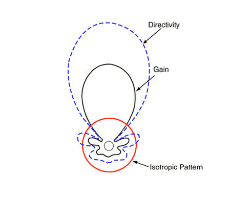
Directivity provides a straightforward response to this query:
"How well does the antenna concentrate its energy in a specific direction?"
Energy is concentrated into a small beam via a high-directivity antenna (like a flashlight).
Energy is distributed more uniformly using a low-directivity antenna (like a light bulb).
How Do You Measure Directivity?
Decibels (dBi) are commonly used to represent directivity, where:
A radiator with 0 dBi is good since it has equal power in all directions.
More concentrated radiation is indicated by higher dBi levels.
In linear terms, the formula for directivity is:
D = 4π × (total radiated power) / (highest radiation intensity)
It is often shown in dBi as:
Directivity (dBi) is equal to 10 × log₁₀(D).
Antenna Examples with Various Directivities
S.No. Antenna Type Typical Directivity (dBi) Pattern
Isotropic Radiator 0 Uniform in all directions
Dipole Antenna ~2.15 Omnidirectional (horizontal)
Yagi-Uda Antenna 7–15 Directional
Parabolic Dish Antenna 20–40+ Highly directional
Patch (Microstrip) Antenna 6–9 Semi-directional
What Makes Directivity Vital?
1. A stronger signal
More energy is concentrated where it is needed when directivity is higher, increasing the effective signal's range and intensity in that direction.
2. Less Interference
High-directivity antennas decrease interference with neighboring systems by concentrating the signal and reducing undesired emission in other directions.
3. Efficiency in Energy Use
In particular, battery-powered or remote equipment like satellite terminals or drones benefit from less power being spent in unwanted directions.
4. Strengthened Security
High-directivity antennas are helpful in military and business applications because their narrower beams minimize signal leakage and the chance of interception.
When to Employ Low vs. High Directivity
1. Use high-directivity antennas (such as parabolic or Yagi) in the following situations:
You require point-to-point, long-range communication.
The signal should be directed at a particular target, such as a base station.
You're working in a loud radio frequency environment.
2. Employ low-directivity antennas, such as omni or dipoles, in the following situations:
You require consistent, wide coverage.
In a coverage area, the antenna is positioned in the middle (e.g., Wi-Fi router).
Wide-area connection and mobility are necessary.
Conclusion
A crucial factor in antenna performance is directivity, which determines the energy's destination and delivery efficiency. Engineers may create wireless systems that are more robust, effective, and dependable by comprehending and selecting the right amount of directivity.
We at Eteily Technologies provide a large selection of antennas designed for a variety of uses, ranging from small omnidirectional solutions to high-gain directional systems. Our staff is prepared to assist you in selecting or creating the ideal antenna, whether you're building a unique IoT device or telecom infrastructure.
Contact Us
Eteily Technologies India Pvt. Ltd.
📍 B28 Vidhya Nagar, Near SBI Bank Bhopal - 462026, Madhya Pradesh 📧 Email: [email protected] 📞 Phone: +91-9993979758 🌐 Website: https://eteily.com
#antenna directivity#directional antenna#omnidirectional antenna#dBi#RF antenna performance#Eteily antenna solutions#parabolic antenna#Yagi antenna
0 notes
Text
Printed Antenna Industry Insights Opportunities, Key Applications & Market Dynamics
The printed antenna market a compound annual growth rate (CAGR) of 14.53% during the forecast period (2025 - 2034). Growing rapidly, driven by demand for compact, flexible, and lightweight antennas across wireless communication, IoT, and automotive sectors. Printed antennas are fabricated using conductive ink and flexible substrates, offering cost-effective and scalable wireless solutions.
Asia-Pacific leads due to strong electronics manufacturing and 5G deployment. North America and Europe follow with high investments in IoT and smart infrastructure.
Market Segmentation
By Type
Microstrip antennas
Printed dipole antennas
Slot antennas
By Material
Polymer
Paper
Glass
By Application
Telecommunication
Consumer electronics
Automotive
Healthcare
Aerospace
By Region
North America, Europe, Asia-Pacific, Latin America, Middle East and Africa
Market Trends
5G Network Expansion Printed antennas are integrated into small cells and wearable 5G devices.
Flexible Electronics Growth in bendable and stretchable electronics boosts demand.
Green Manufacturing Eco-friendly substrates and inks align with sustainability goals.
High-Frequency Compatibility Antennas designed for mmWave and high-speed data transmission.
Segment Insights
Microstrip antennas dominate in smartphones and compact IoT devices. Printed dipole types are used in automotive radar and wireless routers. Slot antennas support high-frequency applications and compact designs.
End-User Insights
Telecom operators deploy them in base stations and consumer devices. Automotive manufacturers use printed antennas in infotainment and ADAS. Healthcare applications include wearables and diagnostic devices.
Key Players
Molex
TE Connectivity
Antenova
DuPont
Laird Connectivity
Linx Technologies
Johnson Electric
Ethertronics
Opportunities and Challenges
Opportunities
IoT ecosystem expansion
Printed electronics development
Wearable device market growth
Challenges
Performance limitations in complex environments
Material durability concerns
Trending Report Highlights
Lab Automation In Genomic Market
Laser Cleaning Market
Power Supply Device Market
Rectifier Market
Rf Front End Module Market
0 notes
Text
RF Antenna Ceramic Patch: A Complete Guide to Efficient Wireless Connectivity
Introduction to RF Antenna Ceramic Patch
In modern electronics, wireless communication plays a vital role. The RF antenna ceramic patch is an essential component that ensures stable and high-quality signal transmission. From laptops to industrial sensors and microcontrollers, these antennas provide compactness, thermal stability, and superior performance.
This guide will explain how RF antenna ceramic patches work, their key features, benefits, and typical applications. Along the way, we will touch on relevant electronics terms like cables, connectors, thermal pads, fuses, switches, microprocessors, and more to give you a comprehensive understanding.
What is an RF Antenna Ceramic Patch?
Understanding the Basics
An RF antenna ceramic patch is a type of microstrip antenna constructed on a ceramic substrate. Unlike flexible antennas, the ceramic material offers high dielectric constant and excellent thermal properties, which results in smaller size and better frequency stability.
Why Ceramic Material?
Ceramic substrates resist thermal fluctuations, oils, and environmental stresses, maintaining consistent antenna performance even in challenging industrial environments. This makes ceramic patch antennas ideal for use in sensitive electronics and safety-critical devices.
How Does an RF Antenna Ceramic Patch Work?
The RF antenna ceramic patch transmits and receives radio frequency signals by converting electrical signals into electromagnetic waves and vice versa. It connects to electronics through cables and connectors, linking devices such as microcontrollers, controllers, and microprocessors.
Due to its ceramic base, the antenna size can be significantly reduced without sacrificing gain or efficiency. This compact size is crucial for integration into compact electronics like laptops and sensors, where space is limited but performance must remain reliable.
Key Features of RF Antenna Ceramic Patch
Compact and Efficient Design
Ceramic’s high dielectric constant enables miniaturization without compromising gain.
The antenna fits perfectly into tight spaces alongside other components like capacitors and LEDs.
Thermal and Environmental Stability
Thermal pads and oils commonly used in electronics don’t affect ceramic antennas’ performance.
They operate reliably across wide temperature ranges, crucial for safety systems and contactors.
High Gain and Signal Integrity
Provides strong signal strength, reducing dropouts in wireless communication.
Minimizes interference, ensuring clean data transmission for controllers and sensors.
Benefits of Using RF Antenna Ceramic Patch in Electronics
Enhanced Wireless Performance
With a ceramic patch antenna, devices benefit from improved signal reception and transmission, vital for seamless communication in laptops, microcontrollers, and other electronic gadgets.
Long-Term Durability
Ceramic materials resist moisture, oils, and mechanical wear, ensuring long-lasting performance, especially in industrial tools and safety devices.
Versatility Across Applications
From wireless sensors to microprocessors in laptops and automotive controllers, ceramic patch antennas adapt to diverse electronics requiring compact and reliable RF connectivity.
Typical Applications of RF Antenna Ceramic Patch
Wireless Communication Devices: Smartphones, tablets, and laptops depend on compact antennas for strong connectivity.
Industrial Sensors: Monitor environmental conditions with wireless data transmission.
Microcontrollers and IoT Devices: Reliable antenna performance is critical for seamless network connections.
Automotive Systems: Remote keyless entry and safety systems utilize ceramic antennas for secure communication.
Medical Electronics: Wireless patient monitoring demands high-performance, stable antennas.
Networking Equipment: Routers and access points integrate ceramic patches for better signal coverage.
How to Choose the Right RF Antenna Ceramic Patch
Consider Operating Frequency
Make sure the antenna supports your device’s RF frequency to ensure optimal performance.
Check Size and Compatibility
Verify the antenna fits within your device’s layout, considering other components like switches, fuses, and connectors.
Evaluate Thermal Environment
If your device uses thermal pads or operates under heat, select antennas with robust thermal stability.
Ensure Connector and Cable Compatibility
Proper integration with your cables and connectors is essential for reducing signal loss and maintaining efficiency.
Tips to Optimize RF Antenna Ceramic Patch Performance
Use high-quality cables and connectors to minimize signal degradation.
Avoid placing metal parts near the antenna to reduce interference.
Maintain clean and secure connections for switches and fuses involved in the circuit.
Use thermal pads appropriately to manage heat without compromising antenna efficiency.
Position the antenna for maximum exposure to signal sources.
Conclusion
The RF antenna ceramic patch is a powerful and reliable solution for modern wireless electronics. Its compact size, thermal stability, and high gain make it perfect for devices ranging from laptops and microcontrollers to industrial sensors and automotive systems.
Understanding its features and applications helps engineers and businesses design better wireless products that are efficient, durable, and safe. If you need consistent wireless performance with minimal space requirements, the ceramic patch antenna is an excellent choice.
0 notes
Text
CHIP Ceramic Patch Antenna vs. Bluetooth Patch Antenna: Which Is More Suitable for Your Device?
In wireless communication device design, antenna selection directly impacts signal transmission quality, device size, and user experience. With the rapid development of fields like the Internet of Things (IoT) and smart wearables, CHIP ceramic patch antennas and Bluetooth patch antennas have become mainstream choices due to their distinct characteristics.

I. Antenna Basics: CHIP Ceramic Patch Antenna vs. Bluetooth Patch Antenna
1. CHIP Ceramic Patch Antenna
Principle and Structure:Utilizes ceramic materials (such as dielectric ceramics) as the substrate, achieving signal transmission and reception through microstrip or radiation patch designs. The high dielectric constant of ceramics allows the antenna to operate at smaller sizes, suitable for high-frequency applications (e.g., 2.4GHz, 5GHz).
Core Advantages:
Multi-Band Compatibility: Supports Wi-Fi, Bluetooth, Zigbee, and other protocols, reducing the number of antennas within a device.
Strong Environmental Resistance: Ceramic material is resistant to high temperatures and corrosion, making it suitable for industrial or outdoor scenarios.
High Signal Purity: Low-loss characteristics reduce signal interference, enhancing transmission stability.
2. Bluetooth Patch Antenna
Principle and Structure:Specifically designed for the Bluetooth frequency band (2.4GHz-2.485GHz), typically using PCB substrates or flexible materials. The structure is simple, and the cost is relatively low.
Core Advantages:
Extreme Miniaturization: Sizes can be as small as 3×1.5mm, suitable for miniature devices (e.g., TWS earbuds).
Low Power Consumption Optimization: Designed for Bluetooth Low Energy (BLE) protocols, extending battery life.
Rapid Integration: No complex matching circuits required, simplifying the development process.
II. Key Comparisons: Which Is More Suitable for Your Device?
Comparison DimensionCHIP Ceramic Patch AntennaBluetooth Patch AntennaApplicable Frequency BandsMulti-band (Wi-Fi/Bluetooth/Zigbee, etc.)Single Bluetooth bandSizeRelatively larger (considering ceramic substrate thickness)Extremely small (suitable for space-constrained devices)CostHigher (due to material and process complexity)Lower (standardized design)Environmental AdaptabilityExcellent (resistant to high temperatures, vibrations)General (depends on PCB protection)Typical ApplicationsSmart home gateways, industrial sensors, smartwatchesBluetooth earbuds, smart tags, medical wearables
Scenario-Based Selection Recommendations
Need Multi-Protocol Support? Choose CHIP Ceramic Patch AntennaFor example, smart home central control devices need to connect to both Wi-Fi and Bluetooth. The multi-band characteristics of ceramic antennas can reduce the number of antennas, optimizing layout.
Kinghelm Case: Their KH-CPA series ceramic antennas support dual-band (2.4GHz/5GHz), applied in smart speakers, enhancing signal coverage by 20%.
Pursuing Extreme Miniaturization? Choose Bluetooth Patch AntennaFor instance, TWS earbuds have limited internal space, making the miniature design of Bluetooth patch antennas an ideal choice.
Kinghelm Case: The KH-BTA series patch antennas measure only 3.2×1.6mm, enabling a brand's earbuds to achieve stable transmission over 10 meters.
Operating in Harsh Environments? Choose Ceramic AntennaIndustrial equipment operating in high-temperature or vibration environments benefits from the high reliability of ceramic materials.
Kinghelm Technical Highlight: Achieved AEC-Q200 automotive-grade certification, withstanding temperatures ranging from -40℃ to 125℃.
III. Kinghelm Solutions: Technology and Services
As a leading domestic supplier of microwave RF antennas, Kinghelm Electronics offers customized antenna solutions for various scenarios:
1. CHIP Ceramic Patch Antenna
KH-CPA Series:
Supports multiple frequency bands, compatible with major global communication protocols.
Uses environmentally friendly ceramic materials, compliant with RoHS standards.
Application Areas: Smartwatches, industrial IoT terminals.
2. Bluetooth Patch Antenna
KH-BTA Series:
Transmission power up to +4dBm, reception sensitivity -96dBm.
Supports Bluetooth 5.2/5.3, with a transmission rate of 2Mbps.
Application Areas: Medical monitoring devices, asset tracking tags.
3. Value-Added Services
Free Simulation Design: Optimize antenna radiation direction based on device structure.
Rapid Prototyping: Provide samples within 5 working days, accelerating product launch.
Global Certification Support: Assist in obtaining FCC, CE certifications, reducing compliance risks.
IV. How to Scientifically Choose an Antenna? 3 Steps
Clarify Requirements: Which frequency bands does the device support? Is multi-protocol compatibility needed?
Assess Environment: What are the operating temperature, humidity, and electromagnetic interference levels?
Balance Costs: With limited budget, prioritize standardized Bluetooth antennas; for high-performance needs, investing in ceramic antennas is worthwhile.
V. Conclusion
Both CHIP ceramic patch antennas and Bluetooth patch antennas have their merits. The key to selection lies in matching the specific needs of the device. Whether pursuing multi-band compatibility or focusing on Bluetooth performance, Kinghelm Electronics offers cost-effective solutions. Their products not only lead in technology but also earn global customer trust.
About Kinghelm
Kinghelm is a leading provider of high-quality electronic components, including RoHS-compliant antennas, wires, plug-ins, switches, and connectors. With over 17 years of experience, the company serves industries including automotive, telecommunications, industrial automation, medical devices, and consumer electronics. Kinghelm is known for its durable, reliable components that meet international standards and are used in applications ranging from renewable energy to IoT devices.
0 notes
Text
Les Antennes: Understanding Their Importance and Functionality
Introduction
In the modern world, communication plays a vital role in our daily lives. From smartphones and televisions to satellites and radio stations, antennas, or les antennes in French, are essential components that facilitate wireless communication. These devices serve as a bridge between transmitters and receivers, enabling the transmission of signals over vast distances. Understanding their functionality, types, and applications can help us appreciate the intricate network that keeps the world connected.

What is an Antenna?
An antenna is a device used to transmit and receive electromagnetic waves. It acts as a converter, transforming electrical signals into radio waves and vice versa. Antennas are found in various electronic systems, including mobile phones, Wi-Fi routers, televisions, and even satellite communication devices.
Antennas are a fundamental part of any wireless communication system, enabling information transfer without the need for physical connections. Their efficiency depends on factors such as frequency, design, and the surrounding environment.
How Do Antennas Work?
Antennas function based on the principles of electromagnetic wave propagation. When an electrical signal is applied to an antenna, it generates an electromagnetic field that radiates outward. Conversely, when an antenna receives an incoming wave, it converts it into an electrical signal, which is then processed by the receiving device.
Antennas operate on specific frequencies, which determine the wavelength and efficiency of the transmission. The relationship between wavelength and frequency is given by the equation:
where is the wavelength, is the speed of light, and is the frequency.
Types of Antennas
There are numerous types of antennas, each designed for specific applications. Below are some of the most common types:
Dipole Antennas
Dipole antennas are among the simplest and most widely used antennas. They consist of two conductive elements and are commonly used in radio and television broadcasting.
Yagi-Uda Antennas
These directional antennas consist of multiple parallel elements, including a driven element, reflector, and one or more directors. They are often used for television reception and amateur radio communication.
Parabolic Antennas
Parabolic antennas, or dish antennas, use a curved reflector to focus radio waves onto a single point. These antennas are ideal for satellite communication and deep-space exploration.
Loop Antennas
Loop antennas consist of a loop of wire and are commonly used in radio communications, including RFID systems and AM radio receivers.
Patch Antennas
Also known as microstrip antennas, these are flat antennas used in modern communication devices such as smartphones, GPS receivers, and Wi-Fi routers.
Helical Antennas
Helical antennas consist of a wire wound in a helix shape and are used in space communication and satellite tracking.
Log-Periodic Antennas
These antennas have a unique structure that allows them to operate over a wide range of frequencies, making them ideal for television broadcasting and signal testing applications.
Applications of Antennas
Antennas are used in a variety of fields, including telecommunications, broadcasting, and scientific research. Here are some key applications:
Radio and Television Broadcasting
Antennas play a crucial role in transmitting and receiving radio and television signals. Broadcasters use high-power antennas to transmit signals over long distances, while consumers use smaller antennas to receive these signals.
Mobile Communication
Mobile phones rely on antennas to communicate with cell towers. These antennas facilitate voice calls, text messaging, and internet access by transmitting and receiving signals from network providers.
Satellite Communication
Satellites use les antennes to transmit data back to Earth. These antennas are essential for GPS navigation, weather forecasting, and global internet coverage.
Radar Systems
Radar systems use antennas to detect objects by transmitting radio waves and analyzing their reflections. This technology is used in aviation, military applications, and weather monitoring.
Wi-Fi and Internet Connectivity
Wi-Fi routers use antennas to provide wireless internet connectivity. These antennas operate at high frequencies to deliver fast and reliable internet access.
Space Exploration
NASA and other space agencies use antennas to communicate with spacecraft and rovers exploring outer space. These high-gain antennas ensure data transmission across vast distances.
Factors Affecting Antenna Performance
Several factors influence the efficiency and effectiveness of an antenna. Some of the key factors include:
Frequency and Wavelength
Antennas must be designed to operate at specific frequencies to ensure optimal performance. The wavelength of the signal affects the antenna's size and design.
Antenna Gain
Gain measures the ability of an antenna to focus energy in a specific direction. Higher gain antennas provide stronger and more directional signals.
Polarization
Polarization refers to the orientation of the electromagnetic wave. Antennas must match the polarization of the transmitting and receiving signals for efficient communication.
Interference and Obstacles
Physical obstructions, such as buildings and trees, can weaken signals. Electromagnetic interference from other devices can also impact antenna performance.
Antenna Placement
Proper placement of an antenna is essential for maximizing signal strength and coverage. Outdoor antennas generally perform better than indoor ones due to fewer obstructions.
The Future of Antenna Technology
As technology advances, antenna design and functionality continue to improve. Some emerging trends in antenna technology include:
5G and Beyond
The deployment of 5G networks requires advanced antennas capable of handling higher frequencies and faster data transmission. Massive MIMO (Multiple Input Multiple Output) antennas are being developed to improve network capacity.
Smart Antennas
Smart antennas use advanced algorithms to dynamically adjust their direction and frequency, improving signal quality and reducing interference.
Wearable and Flexible Antennas
Researchers are developing antennas that can be integrated into clothing and flexible surfaces, enabling new applications in healthcare, fitness, and smart textiles.
Space-Based Antennas
Future space missions will require advanced antennas for deep-space communication, enabling real-time data transfer between Earth and distant planets.
Conclusion
Antennas, or "les antennes," are indispensable components of modern communication systems. From enabling television and radio broadcasts to supporting space exploration, antennas play a critical role in connecting the world. With continuous advancements in technology, antennas are evolving to meet the demands of the future, paving the way for faster and more efficient communication. Understanding their principles, types, and applications helps us appreciate the intricate network that keeps us connected in today's digital age.
0 notes
Text
According to the new research report, the "Defense Integrated Antenna Market by Type (Aperture Antenna, Wire Antenna, Array Antenna, Microstrip Antenna), Platform (Ground, Airborne, Marine), Application, Frequency and Region (North America, APAC, Europe, MEA, RoW) - Forecast to 2026", published by MarketsandMarkets™, the market is projected to grow from USD 543 million in 2022 to USD 722 million by 2026, at a CAGR of 5.8% during the forecast period.
0 notes
Text
Exploring the Different Types of RF Antennas
Radio Frequency (RF) antennas are crucial components in a wide range of communication systems, including cellular networks, satellite communications, Wi-Fi, and Bluetooth technologies. Their major job is to transform electrical signals into electromagnetic waves, which they then transmit and receive. The design, selection, and implementation of the appropriate antenna type has a significant impact on communication system performance, range, and efficiency. In this article, we will look at the many types of RF antennas, their properties, applications, and when to utilize each one.
1. Dipole antennas
The dipole antenna is one of the simplest and most used types of antenna. It consists of two conducting pieces, usually made of metal, aligned in a straight line with a feed point in the middle. The dipole antenna functions at its resonant frequency when its entire length is roughly half the wavelength of the signal.
Characteristics:
Simple design
Ideal for sending and receiving omnidirectional signals in the horizontal plane.
Effective for frequencies from 30 MHz to 300 MHz (HF to UHF bands)
Applications:
Used for radio transmission and reception.
Frequently used in television and radio transmission.
simple communication systems, such as walkie-talkies.
2. Monopole antennas
A monopole antenna is similar to a dipole, except it has a single conducting element positioned above the ground plane. This ground plane functions as a reflector, which improves the antenna's effectiveness. The monopole antenna is essentially a half-dipole antenna with a ground plane to complete the circuit.
Characteristics:
Needs a ground plane or reflective surface.
Compact and easily integrated into mobile devices.
Typically performs well in vertical polarization patterns.
Applications:
Cell phones and other mobile devices
utilized in radio and television transmission systems.
Found in GPS and other communication devices.
3. Yagi-Uda antennas
The Yagi-Uda antenna is a highly directional antenna made up of several elements, including a driving element, a reflector, and one or more directors. The driven element is often a dipole, whereas the reflector and directors are passive components that help focus the signal in a specific direction.
Characteristics:
Highly directional and provides significant gain in a particular direction.
Precise alignment is required for best performance.
Can be constructed for a broad variety of frequencies.
Applications:
Used for television reception.
Satellite communications systems
Radar and wireless communication applications.
4. Parabolic antennas
Parabolic antennas, also known as parabolic dishes, have a curved shape that directs receiving signals to a single focal point, where the receiver or transmitter is positioned. This form enables for great directivity and gain.
Characteristics:
Very high gain and great directivity.
Frequently used in satellite communication and radar systems.
Large and hefty, they are appropriate for fixed installations.
Applications:
Used for satellite communication, such as dish antennas.
Radar systems are used for weather monitoring and military purposes.
Long-range point-to-point wireless transmission.
5. Patch antennas
Patch antennas, also known as microstrip antennas, are flat, small antennas made up of a conducting patch mounted on top of a dielectric substrate. These antennas are normally square, rectangular, or circular, and can be tailored to certain frequencies.
Characteristics:
Small, lightweight, and easily integrated into gadgets.
Low profile makes them excellent for tiny devices.
Can be designed for a broad range of frequencies and polarizations.
Applications:
GPS receivers and smartphones
Used in wireless communication systems, such as Wi-Fi and Bluetooth.
Frequently utilized in aircraft and military systems for radar and communication.
6. Helical antennas
Helical antennas feature a spiral-shaped conductor twisted around a central axis. These antennas can operate in both axial and normal modes, with the axial mode producing a more directed radiation pattern.
Characteristics:
Compact, has a broad bandwidth.
It produces circular polarization, which is suitable for satellite communications.
Depending on the design, radiation patterns might be omnidirectional or directed.
Applications:
Satellite Communication
Space Exploration and Communication
Used in some GPS and mobile communications.
7. Log-periodic Antennas A log-periodic antenna is made up of several elements of varied lengths set in a periodic pattern along a central boom. This design enables the antenna to function over a wide variety of frequencies without having to be retuned.
Characteristics:
Wide bandwidth and multi-frequency operation.
Directional antennas provide strong gain in a single direction.
Can be pretty huge depending on frequency coverage.
Applications:
Broadcasting and receiving various TV and radio broadcasts.
Used in radio frequency measurement and testing equipment.
Found in R&D, including antenna testing setups.
8. Slot antennas
Slot antennas are a form of aperture antenna in which a slot or gap is carved into a conducting surface. These antennas are often installed on a metal plate or within a waveguide construction and are distinguished by their unique qualities, such as wide bandwidth and low profile.
Characteristics:
Compact design with good performance.
Wide bandwidth and low radiation resistance.
Suitable for both circular and linear polarization.
Applications:
Frequently used in radar and communication systems.
Common in military and aviation applications.
Used in specific microwave systems.
9. Aperture antennas
Aperture antennas, such as horn antennas, use an aperture (a hole or opening) in a conductor to emit electromagnetic waves. These antennas are commonly employed in higher frequency ranges.
Characteristics:
Provide a highly directional beam of radiation.
High efficiency and very simple construction
Generally larger and utilized in specialist applications.
Applications:
High-frequency communication systems.
Radar and satellite communication
Used for RF testing and some scientific purposes.
Conclusion
A variety of criteria influence the selection of an RF antenna, including frequency range, desired gain, polarization, and application. While certain antennas, such as the dipole and monopole, are basic and ideal for general communication systems, others, such as the parabolic and Yagi-Uda antennas, provide high gain and directivity for more specialized applications. Understanding the properties of each antenna type enables engineers to choose the best one for a given application, hence improving performance, efficiency, and cost. Whether for long-range satellite communications or short-range wireless systems, the RF antenna is still an essential component of current communication networks.
0 notes
Text
Exploring The World Above: A Deep Dive Into Satellite Antennas

In the vast expanse of space, communication is key to our understanding of the universe. Satellite antennas serve as the vital link between Earth and the cosmos, enabling us to transmit and receive data across vast distances. From weather forecasting to global telecommunications, these antennas play a crucial role in various industries and scientific endeavors. In this article, we delve into the fascinating world of satellite antennas, exploring their functionality, types, applications, and the future of satellite communication.
Understanding Satellite Antennas
At its core, a satellite antenna is a device designed to send and receive electromagnetic signals to and from satellites orbiting the Earth. These antennas come in various shapes and sizes, each optimized for specific purposes and frequencies. The primary function of a satellite antenna is to capture signals from satellites in orbit and to transmit signals back to them, facilitating two-way communication.
Types of Satellite Antennas

Satellite antennas can be classified based on their design, frequency range, and application. Some common types include:
Parabolic Dish Antennas: Perhaps the most recognizable type, parabolic dish antennas consist of a concave dish-shaped reflector and a feedhorn at the focal point. These antennas are highly directional and are commonly used for satellite television broadcasting and satellite internet services.
Yagi Antennas: Yagi antennas, also known as beam antennas, are composed of multiple parallel elements, including a driven element, reflector, and one or more directors. These antennas are widely used for terrestrial and satellite communication in both urban and rural areas.
Horn Antennas: Horn antennas are characterized by their flared, horn-shaped structure. They are often used for radar systems, satellite tracking, and microwave communication due to their wide bandwidth and high gain.
Patch Antennas: Patch antennas, also known as microstrip antennas, are flat, compact antennas commonly used in satellite communication, GPS systems, and wireless networks. They offer advantages such as low profile and ease of integration into electronic devices.
Applications of Satellite Antennas
Satellite antennas have a wide range of applications across various industries and scientific fields:
Telecommunications: Satellite antennas enable long-distance communication, facilitating global telephony, internet access, and broadcasting services. They play a crucial role in connecting remote and underserved regions to the global network.
Weather Forecasting: Weather satellites equipped with specialized antennas provide invaluable data for meteorological forecasting. These antennas capture images and atmospheric data, helping meteorologists track weather patterns and predict severe weather events.
Navigation: Satellite navigation systems, such as GPS (Global Positioning System), rely on antennas to receive signals from orbiting satellites and determine precise location information. These systems are used in navigation devices, smartphones, and vehicle tracking systems.
Earth Observation: Satellites equipped with high-resolution cameras and sensors use antennas to transmit images and data back to Earth. This data is used for environmental monitoring, agriculture, urban planning, and disaster management.
Scientific Research: Satellite antennas support a wide range of scientific research endeavors, including space exploration, astronomy, and climate studies. They enable scientists to gather data from remote locations in space and monitor phenomena such as solar activity and climate change.
Challenges and Future Trends

While many antennas have revolutionized communication and observation capabilities, they also face several challenges:
Signal Interference: Interference from terrestrial sources, such as radio frequency interference (RFI) and electromagnetic interference (EMI), can degrade signal quality and disrupt communication links. Advanced signal processing techniques and frequency management strategies are being developed to mitigate these issues.
Orbital Debris: The growing population of space debris poses a threat to satellites and their antennas. Collision avoidance measures and debris mitigation strategies are essential to safeguarding space infrastructure.
Bandwidth Limitations: With the increasing demand for high-speed internet and data transmission, there is a need for higher bandwidth satellite communication systems. Advances in antenna technology, such as phased array antennas and frequency reuse techniques, are being explored to address this challenge.
Looking ahead, the future of satellite antennas is poised for exciting developments. Emerging technologies such as 5G satellite networks, small satellites (CubeSats), and constellations of interconnected satellites promise to revolutionize communication, navigation, and Earth observation capabilities. Additionally, advancements in materials science and manufacturing techniques may lead to the development of lighter, more durable antennas with enhanced performance.
Advancements in Phased Array Antennas: Phased array antennas represent a significant advancement in satellite communication technology. Unlike traditional dish antennas, phased array antennas use multiple small antenna elements controlled by phase shifters to steer the antenna beam electronically. This enables rapid beam scanning, improved signal tracking, and the ability to establish communication with multiple satellites simultaneously. Phased array antennas offer greater flexibility, reliability, and efficiency, making them ideal for applications such as mobile satellite communication, military surveillance, and satellite-based internet services.

The emergence of LEO Satellite Constellations: Low Earth Orbit (LEO) satellite constellations have emerged as a disruptive force in the satellite communication industry. These constellations consist of hundreds or even thousands of small satellites orbiting the Earth at altitudes ranging from a few hundred to a few thousand kilometers. LEO constellations, such as SpaceX’s Starlink and OneWeb, leverage antennas to provide high-speed internet access to underserved and remote areas around the globe. By deploying dense networks of satellites with interconnected antennas, LEO constellations offer low-latency, high-bandwidth communication capabilities, revolutionizing the way we connect to the internet.
Conclusion:
In conclusion, satellite antennas are the unsung heroes of modern communication and observation systems. From enabling global connectivity to enhancing scientific exploration, these antennas play a vital role in our interconnected world. As technology continues to evolve, satellite antennas will remain at the forefront of innovation, paving the way for new discoveries and advancements in the realms of space exploration and telecommunications.
#SatelliteAntennas#SpaceCommunication#FutureTech#SatelliteTechnology#LEOConstellations#InterSatelliteCommunication
0 notes
Text
Unlocking Opportunities: Aircraft Antenna Market Set to Reach $0.9 Billion by 2026
The Aircraft Antenna Market is poised for substantial growth, with an estimated valuation of USD 0.6 billion in 2021, projected to escalate to USD 0.9 billion by 2026, registering a robust CAGR of 7.9% during the forecast period. This growth trajectory is underpinned by several key factors, including the proliferation of airspace modernization programs, rising demand for military UAVs, and the introduction of advanced aircraft systems.
The Aircraft Antenna Market presents significant growth prospects driven by evolving market dynamics, technological innovations, and strategic initiatives undertaken by key players. Despite the challenges posed by the COVID-19 pandemic, the market is poised for robust expansion, fueled by increasing investments in airspace modernization and the escalating demand for advanced aircraft systems globally.
Download PDF Brochure: https://www.marketsandmarkets.com/pdfdownloadNew.asp?id=76582743
Market Trends and Segmentation Insights:
VHF & UHF Band Segment: Foreseen to lead the market during the forecast period, driven by its indispensable role in short-range aircraft navigation and communication applications.
Terminal Wireless Local Area Network Segment: Projected to witness the highest CAGR, propelled by its multi-protocol support and facilitation of wireless content and data transfer at airports.
Microstrip Antenna Segment: Expected to experience the highest CAGR, owing to its cost-effectiveness, ease of fabrication, and lightweight nature, making it a preferred choice for various aerospace applications.
Nose Mounted Segment: Anticipated to exhibit robust growth, attributed to the installation of critical radar antennas and communication equipment essential for aircraft functionality.
OEM Segment: Poised to witness significant growth, driven by technological advancements and the escalating need for enhanced connectivity and communication in the aviation sector.
UAV Segment: Forecasted to register the highest CAGR, fueled by the expanding utility of UAVs in defense activities, where smaller and lighter antennas are increasingly favored.
Regional Analysis: North America is expected to command a substantial share of the Aircraft Antenna Market from 2021 to 2026, propelled by the region's burgeoning demand for new aircraft and their extensive application in both commercial and defense domains. The robust growth of the North American aircraft antenna market is further bolstered by key players like L3Harris Technologies Inc. and The Boeing Company.
Inquiry Before Buying: https://www.marketsandmarkets.com/Enquiry_Before_BuyingNew.asp?id=76582743
Key Player Strategies: Major players in the Aircraft Antenna Market, including L3Harris Technologies Inc., Honeywell International, Collins Aerospace, Cobham Limited, and The Boeing Company, have adopted a range of organic and inorganic strategies to fortify their market position. These strategies encompass acquisitions, contracts, new product launches, and partnerships & agreements, enabling them to expand their market presence and consolidate their competitive edge.
0 notes
Text
Understanding the Antenna Design Process: From Concept to Prototype
In today's hyper-connected world, antennas are at the heart of all wireless communication systems, from smartphones and IoT devices to satellite networks and industrial automation. Antennas may appear to be simple components, but they require a complicated design approach to provide high-performance, dependable communications. This article describes the antenna design process, from first concept to functional prototype.

1. Understanding the application and requirements
The design process begins with a thorough understanding of the application, which determines all aspects of the antenna's properties.
Key Considerations:
Frequency band (for example, 2.4 GHz for Wi-Fi, 868 MHz for LoRa, and so on).
Polarization (linear, circular, elliptical)
Radiation patterns (omnidirectional, directional, or beamforming)
Size limitations (particularly for tiny or embedded electronics)
Environment (indoor, outdoor, rough, medical, etc.)
Defining these criteria ensures that the antenna meets its performance, regulatory, and mechanical requirements.
2. Choosing the Right Antenna Type
Based on the application, the designer determines the most appropriate antenna type:
Monopole/Dipole Antennas - Simple, small, and widely utilised in consumer electronics.
Patch (Microstrip) Antennas are compact and appropriate for use in embedded systems.
Yagi Antennas are directional, long-range antennas used for distant or point-to-point applications.
Helical and loop antennas are suitable for compact devices or specialized polarization.
Array antennas are used in a variety of modern applications, including 5G, radar, and beamforming.
3. Simulation and Modeling
The antenna is then virtually developed and tested using RF simulation tools, such as:
CST Microwave Studio
HFSS (high-frequency structure simulator)
FEKO
ADS (Advanced Design Systems)
Simulation enables engineers to model
Return Loss (S11)
Voltage Standing Wave Ratio (VSWR).
Gain and Efficiency
Radiation pattern
Impedance Matching
Designers optimize the antenna's size, materials, and geometries before it is physically created.
4. Material Selection and PCB Integration
Material selection has a significant influence on signal behaviour.
Copper is a popular conductive material for traces and components.
For low-cost designs, use FR4, whereas Rogers/PTFE is recommended for high-frequency applications.
Housing materials: Plastic or ABS enclosures must be RF-transparent.
For PCB antennas, integration with the board's layout is critical, including ground plane size, clearance, and location in relation to other components.
5. Prototype and Fabrication
Once the simulation findings are satisfactory, it is time to proceed to practical prototyping.
Common manufacturing processes include PCB etching for microstrip antennas.
3D printing and metal plating are used to create custom-shaped antennas.
Wire bending or CNC machining is used for big or high-power antennas.
After production, the prototype is put to the test in real-world situations.
6. Testing & Validation
Testing determines whether the prototype achieves the original performance objectives.
Lab tests include:
Anechoic chamber testing to assess gain, pattern, and efficiency.
VSWR and S-parameters analysis with vector network analysers (VNAs)
Environmental stress testing (temperature, vibration, and moisture).
If the performance does not meet expectations, the design is iterated by modifying size, tweaking parts, or improving the layout.
7. Final Optimization and Production Readiness
After the prototype is validated, the design is optimised for mass production.
Simplify the manufacturing processes.
Standardise materials to keep costs under control.
Minimise component variance to ensure consistent performance.
At this point, the antenna is ready for incorporation into commercial devices or independent goods.
Conclusion
Antenna design is a science and an art that combines RF theory, material science, mechanical design, and practical testing. From establishing use cases to building a functioning prototype, each step guarantees that the finished antenna provides dependable, high-performance connectivity.
Eteily Technologies specialises in bespoke antenna design and prototype, providing comprehensive solutions for IoT, telecom, automotive, and industrial applications.
Contact Us
Eteily Technologies India Pvt. Ltd.
📍 B28 Vidhya Nagar, Near SBI Bank Bhopal - 462026, Madhya Pradesh 📧 Email: [email protected] 📞 Phone: +91-9993979758 🌐 Website: https://eteily.com
#antenna design process#RF antenna prototype#antenna simulation#VSWR#patch antenna#PCB antenna#directional antenna#wireless communication#Eteily RF solutions
0 notes
Text
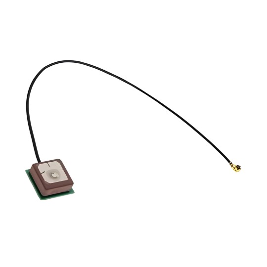
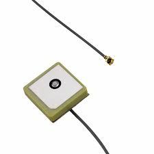
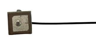
What are the applications of microstrip antenna ?

Theories and designs for B Tech in Electronics and Communications
Microstrip antenna is the most popular types of printed antenna. In today’s wireless communication systems or degrees like B Tech in Electronics and Communication Engineering, these play a very important role. It is one of the critical components in any wireless communication system. In other words, the antenna is a part of a transmitting or receiving system that designs to radiate or receive electromagnetic waves.
Classification of different antenna
Antennae broadly divided into several categories. It includes:
Wire antennae – This is the most basic type of antenna. It uses widely on the top of buildings, ships, automobiles, and spacecraft by the students of the list of engineering colleges in Jaipur. After all, these antennae are made into different shapes like the loop, straight wire (dipole), and helix.
Aperture antennae – These are in the form of a slot or aperture in a metal plate. They commonly use at higher frequencies like 3-30 GHz by the students of B Tech College in Jaipur. For instance, slotted waveguide antennae and horn antennae. They are very useful for aircraft and spacecraft applications because they can be conveniently flush-mounted on the surface of the spacecraft or aircraft.
Printed antennae – A printed antenna is fabricated and makes use of standard photolithography technique. The most common version of the printed antenna is a microstrip antenna. In addition, it consists of a metallic patch above a ground plane. Therefore, the shape and size of the patch mainly determine the frequency of operation including its antenna and performance.
There are various other types of antennas which include array antennae, reflector antennae, lens antennae, etc.
Applications of the most common printed microstrip antennae
Microstrip patch antenna finds several applications in wireless communication for the students of Top Engineering Colleges in Jaipur. For instance, satellite communication requires circularly polarize radiation patterns that can be realized using either circular or square or circular patch microstrip antenna. In global positioning satellite (GPS) systems, circularly polarize microstrip antennae can be used. They are very compact in size and quite expensive due to their positions.
Mobile communication
Mobile communication requires low or small cost, low-profile antennae. In some mobile handsets, diodes or detectors depends on semiconductor uses as antennae by the individuals of Best B Tech College in Jaipur. However, they are similar to the p-n diode photo-detectors but work in relation to the microwave frequency.
Medical applications
The treatment of malignant tumors allows the microwave energy to induce hyperthermia. However, the radiator should be easy-to-handle for the individuals of Engineering Colleges in Jaipur, light-weight, and rugged. Only a patch radiator fulfills these requirements.
Textile antennae: recent research
Based on the different types of antennae, students of Best Engineering Colleges in Jaipur continuously monitor the biometric data of the human body. It requires the nearest positions to the human body so that the individuals can send the information can happen outside the world. The hard antennae should not attach to the human body. In addition, it consists of textile material that will not harm the human body and can be worn for extended periods.
Thanks for Read our blog, you can check out full blog on official Page Arya College, Arya College is one of the Best Engineering College In Jaipur Rajasthan. In This College Many Branches for Engineering you can make great future with us. Arya College Provides Computer Engineering, Electrical Engineering & Electronics Engineering’s Branch for our Engineering students with top companies placements in campus.
0 notes
Text
CHIP Ceramic Patch Antenna vs. Bluetooth Patch Antenna: Which Is More Suitable for Your Device?
In wireless communication device design, antenna selection directly impacts signal transmission quality, device size, and user experience. With the rapid development of fields like the Internet of Things (IoT) and smart wearables, CHIP ceramic patch antennas and Bluetooth patch antennas have become mainstream choices due to their distinct characteristics.
I. Antenna Basics: CHIP Ceramic Patch Antenna vs. Bluetooth Patch Antenna
1. CHIP Ceramic Patch Antenna
Principle and Structure: Utilizes ceramic materials (such as dielectric ceramics) as the substrate, achieving signal transmission and reception through microstrip or radiation patch designs. The high dielectric constant of ceramics allows the antenna to operate at smaller sizes, suitable for high-frequency applications (e.g., 2.4GHz, 5GHz).
Core Advantages:
Multi-Band Compatibility: Supports Wi-Fi, Bluetooth, Zigbee, and other protocols, reducing the number of antennas within a device.
Strong Environmental Resistance: Ceramic material is resistant to high temperatures and corrosion, making it suitable for industrial or outdoor scenarios.
High Signal Purity: Low-loss characteristics reduce signal interference, enhancing transmission stability.
2. Bluetooth Patch Antenna
Principle and Structure: Specifically designed for the Bluetooth frequency band (2.4GHz-2.485GHz), typically using PCB substrates or flexible materials. The structure is simple, and the cost is relatively low.
Core Advantages:
Extreme Miniaturization: Sizes can be as small as 3×1.5mm, suitable for miniature devices (e.g., TWS earbuds).
Low Power Consumption Optimization: Designed for Bluetooth Low Energy (BLE) protocols, extending battery life.
Rapid Integration: No complex matching circuits required, simplifying the development process.
II. Key Comparisons: Which Is More Suitable for Your Device?
Comparison DimensionCHIP Ceramic Patch AntennaBluetooth Patch AntennaApplicable Frequency BandsMulti-band (Wi-Fi/Bluetooth/Zigbee, etc.)Single Bluetooth bandSizeRelatively larger (considering ceramic substrate thickness)Extremely small (suitable for space-constrained devices)CostHigher (due to material and process complexity)Lower (standardized design)Environmental AdaptabilityExcellent (resistant to high temperatures, vibrations)General (depends on PCB protection)Typical ApplicationsSmart home gateways, industrial sensors, smartwatchesBluetooth earbuds, smart tags, medical wearables
Scenario-Based Selection Recommendations
Need Multi-Protocol Support? Choose CHIP Ceramic Patch Antenna For example, smart home central control devices need to connect to both Wi-Fi and Bluetooth. The multi-band characteristics of ceramic antennas can reduce the number of antennas, optimizing layout.
Kinghelm Case: Their KH-CPA series ceramic antennas support dual-band (2.4GHz/5GHz), applied in smart speakers, enhancing signal coverage by 20%.
Pursuing Extreme Miniaturization? Choose Bluetooth Patch Antenna For instance, TWS earbuds have limited internal space, making the miniature design of Bluetooth patch antennas an ideal choice.
Kinghelm Case: The KH-BTA series patch antennas measure only 3.2×1.6mm, enabling a brand's earbuds to achieve stable transmission over 10 meters.
Operating in Harsh Environments? Choose Ceramic Antenna Industrial equipment operating in high-temperature or vibration environments benefits from the high reliability of ceramic materials.
Kinghelm Technical Highlight: Achieved AEC-Q200 automotive-grade certification, withstanding temperatures ranging from -40℃ to 125℃.
III. Kinghelm Solutions: Technology and Services
As a leading domestic supplier of microwave RF antennas, Kinghelm Electronics offers customized antenna solutions for various scenarios:
1. CHIP Ceramic Patch Antenna
KH-CPA Series:
Supports multiple frequency bands, compatible with major global communication protocols.
Uses environmentally friendly ceramic materials, compliant with RoHS standards.
Application Areas: Smartwatches, industrial IoT terminals.
2. Bluetooth Patch Antenna
KH-BTA Series:
Transmission power up to +4dBm, reception sensitivity -96dBm.
Supports Bluetooth 5.2/5.3, with a transmission rate of 2Mbps.
Application Areas: Medical monitoring devices, asset tracking tags.
3. Value-Added Services
Free Simulation Design: Optimize antenna radiation direction based on device structure.
Rapid Prototyping: Provide samples within 5 working days, accelerating product launch.
Global Certification Support: Assist in obtaining FCC, CE certifications, reducing compliance risks.
IV. How to Scientifically Choose an Antenna? 3 Steps
Clarify Requirements: Which frequency bands does the device support? Is multi-protocol compatibility needed?
Assess Environment: What are the operating temperature, humidity, and electromagnetic interference levels?
Balance Costs: With limited budget, prioritize standardized Bluetooth antennas; for high-performance needs, investing in ceramic antennas is worthwhile.
V. Conclusion
Both CHIP ceramic patch antennas and Bluetooth patch antennas have their merits. The key to selection lies in matching the specific needs of the device. Whether pursuing multi-band compatibility or focusing on Bluetooth performance, Kinghelm Electronics offers cost-effective solutions. Their products not only lead in technology but also earn global customer trust.

About Kinghelm
Kinghelm is a leading provider of high-quality electronic components, including RoHS-compliant antennas, wires, plug-ins, switches, and connectors. With over 17 years of experience, the company serves industries including automotive, telecommunications, industrial automation, medical devices, and consumer electronics. Kinghelm is known for its durable, reliable components that meet international standards and are used in applications ranging from renewable energy to IoT devices.
0 notes
Text
Quantum Calculator

Photodiode Quantum Efficiency | Definition, equation, calculator
Quantum performance calculator quantum performance calc the quantum performance score quantifies strength performance for people of different sizes (height and weight). Use the form below to work out the quantum performance score and quantum performance level you require for recomp certification. VQE is a quantum–classical hybrid algorithm and has been extensively studied because it is executable on noisy intermediate-scale quantum (NISQ) devices. Apart from these two approaches, many studies of quantum chemical calculations on quantum computers have been reported from both the theoretical and experimental sides.
Quantum Calculator Google
This page describes Photodiode Quantum Efficiency definition. It mentions Photodiode Quantum Efficiency equation/formula andPhotodiode Quantum Efficiency calculator.
What is Photodiode ?
• A photodiode is a type of photodetector capable of converting light into either current or voltage.This effect is called photovoltaic effect. • DC source is often used to apply reverse bias to the photodiode. This makes it generate more current.This mode of operation is called photoconductive mode. • Applications of photodiode include optical disc drives, digital cameras and optical switches etc. • Variants : PIN photodiode, Avalanche photodiode, PN Photodiode, Schottky Photodiode etc.

The figure depicts symbol of Photodiode and one such device from OSRAM.Refer article on Photodiode basics and types and their working operation.
What is Photodiode Quantum Efficiency ?
Definition:The quantum efficiency is defined as fraction of incident photons which are absorbed by photoconductor andgenerated electrons which are collected at the detector terminal.
In other words, Quantum efficiency is defined as fraction of incident photonswhich contribuite to photocurrent.It is related to responsivity as per following equation. Q.E. = 1240 * (Rλ/λ) ; Where, Rλ = Responsivity in A/W and λ = Wavelength in nm
Photodiode Quantum Efficiency Calculator
Example of Photodiode Quantum Efficiency calculator: INPUTS : Re = 1e5, Rp = 1.5e5 OUTPUTS: Quantum Efficiency (Q.E.) = 66.66%
Photodiode Quantum Efficiency Equation | Photodiode Quantum Efficiency Formula
Following equation or formula is used for Photodiode Quantum Efficiency calculator.
Photodiode calculators and terminologies
Photodiode vs Phototransistor Difference between Photodiode types and PIN diode Quantum Efficiency Responsivity Sensitivity
Useful converters and calculators
Following is the list of useful converters and calculators. dBm to Watt converter Stripline Impedance calculator Microstrip line impedance Antenna G/T Noise temp. to NF
RF and Wireless tutorials
Share this page
Translate this page
Quantum Numbers, Atomic Orbitals, and Electron Configurations
Contents: Quantum Numbers and Atomic Orbitals 1. Principal Quantum Number (n) 2.Angular Momentum (Secondary, Azimunthal) Quantum Number (l) 3.Magnetic Quantum Number (ml) 4.Spin Quantum Number (ms) Table of Allowed Quantum Numbers Writing Electron Configurations Properties of Monatomic Ions References
Quantum Numbers and Atomic Orbitals
By solving the Schrödinger equation (Hy = Ey), we obtain a set of mathematical equations, called wave functions (y), which describe the probability of finding electrons at certain energy levels within an atom.
A wave function for an electron in an atom is called an atomic orbital; this atomic orbital describes a region of space in which there is a high probability of finding the electron. Energy changes within an atom are the result of an electron changing from a wave pattern with one energy to a wave pattern with a different energy (usually accompanied by the absorption or emission of a photon of light).
Each electron in an atom is described by four different quantum numbers. The first three (n, l, ml) specify the particular orbital of interest, and the fourth (ms) specifies how many electrons can occupy that orbital.
Principal Quantum Number (n): n = 1, 2, 3, …, ∞ Specifies the energy of an electron and the size of the orbital (the distance from the nucleus of the peak in a radial probability distribution plot). All orbitals that have the same value of n are said to be in the same shell (level). For a hydrogen atom with n=1, the electron is in its ground state; if the electron is in the n=2 orbital, it is in an excited state. The total number of orbitals for a given n value is n2.
Angular Momentum (Secondary, Azimunthal) Quantum Number (l): l = 0, ..., n-1. Specifies the shape of an orbital with a particular principal quantum number. The secondary quantum number divides the shells into smaller groups of orbitals called subshells (sublevels). Usually, a letter code is used to identify l to avoid confusion with n:
l012345...Letterspdfgh...
The subshell with n=2 and l=1 is the 2p subshell; if n=3 and l=0, it is the 3s subshell, and so on. The value of l also has a slight effect on the energy of the subshell; the energy of the subshell increases with l (s < p < d < f).

Magnetic Quantum Number (ml): ml = -l, ..., 0, ..., +l. Specifies the orientation in space of an orbital of a given energy (n) and shape (l). This number divides the subshell into individual orbitals which hold the electrons; there are 2l+1 orbitals in each subshell. Thus the s subshell has only one orbital, the p subshell has three orbitals, and so on.
Spin Quantum Number (ms): ms = +½ or -½. Specifies the orientation of the spin axis of an electron. An electron can spin in only one of two directions (sometimes called up and down). The Pauli exclusion principle (Wolfgang Pauli, Nobel Prize 1945) states that no two electrons in the same atom can have identical values for all four of their quantum numbers. What this means is that no more than two electrons can occupy the same orbital, and that two electrons in the same orbital must have opposite spins. Because an electron spins, it creates a magnetic field, which can be oriented in one of two directions. For two electrons in the same orbital, the spins must be opposite to each other; the spins are said to be paired. These substances are not attracted to magnets and are said to be diamagnetic. Atoms with more electrons that spin in one direction than another contain unpaired electrons. These substances are weakly attracted to magnets and are said to be paramagnetic.
Table of Allowed Quantum Numbers
nlmlNumber of orbitalsOrbital NameNumber of electrons10011s220012s21-1, 0, +132p630013s21-1, 0, +133p62-2, -1, 0, +1, +253d1040014s21-1, 0, +134p62-2, -1, 0, +1, +254d103-3, -2, -1, 0, +1, +2, +374f14
Writing Electron Configurations
The distribution of electrons among the orbitals of an atom is called the electron configuration. The electrons are filled in according to a scheme known as the Aufbau principle ('building-up'), which corresponds (for the most part) to increasing energy of the subshells:
1s, 2s, 2p, 3s, 3p, 4s, 3d, 4p, 5s, 4d, 5p, 6s, 4f, 5d, 6p, 7s, 5f
It is not necessary to memorize this listing, because the order in which the electrons are filled in can be read from the periodic table in the following fashion:
Or, to summarize:
In electron configurations, write in the orbitals that are occupied by electrons, followed by a superscript to indicate how many electrons are in the set of orbitals (e.g., H 1s1)
Another way to indicate the placement of electrons is an orbital diagram, in which each orbital is represented by a square (or circle), and the electrons as arrows pointing up or down (indicating the electron spin). When electrons are placed in a set of orbitals of equal energy, they are spread out as much as possible to give as few paired electrons as possible (Hund's rule).
examples will be added at a later date
In a ground state configuration, all of the electrons are in as low an energy level as it is possible for them to be. When an electron absorbs energy, it occupies a higher energy orbital, and is said to be in an excited state.
Properties of Monatomic Ions
The electrons in the outermost shell (the ones with the highest value of n) are the most energetic, and are the ones which are exposed to other atoms. This shell is known as the valence shell. The inner, core electrons (inner shell) do not usually play a role in chemical bonding.
Elements with similar properties generally have similar outer shell configurations. For instance, we already know that the alkali metals (Group I) always form ions with a +1 charge; the 'extra' s1 electron is the one that's lost:
IALi1s22s1Li+1s2Na1s22s22p63s1Na+1s22s22p6K1s22s22p63s23p64s1K+1s22s22p63s23p6
The next shell down is now the outermost shell, which is now full — meaning there is very little tendency to gain or lose more electrons. The ion's electron configuration is the same as the nearest noble gas — the ion is said to be isoelectronic with the nearest noble gas. Atoms 'prefer' to have a filled outermost shell because this is more electronically stable.
The Group IIA and IIIA metals also tend to lose all of their valence electrons to form cations.
Quantum Calculator
IIABe1s22s2Be2+1s2Mg1s22s22p63s2Mg2+1s22s22p6IIIAAl1s22s22p63s23p1Al3+1s22s22p6
The Group IV and V metals can lose either the electrons from the p subshell, or from both the s and p subshells, thus attaining a pseudo-noble gas configuration.
IVASn(Kr)4d105s25p2Sn2+(Kr)4d105s2Sn4+(Kr)4d10Pb(Xe)4f145d106s26p2Pb2+(Xe)4f145d106s2Pb4+(Xe)4f145d10VABi(Xe)4f145d106s26p3Bi3+(Xe)4f145d106s2Bi5+(Xe)4f145d10
The Group IV - VII non-metals gain electrons until their valence shells are full (8 electrons).
Calculator Quantum Computer
IVAC1s22s22p2C4-1s22s22p6VAN1s22s22p3N3-1s22s22p6VIAO1s22s22p4O2-1s22s22p6VIIAF1s22s22p5F-1s22s22p6
Quantum Calculation In Chemistry
The Group VIII noble gases already possess a full outer shell, so they have no tendency to form ions.
Transition metals (B-group) usually form +2 charges from losing the valence s electrons, but can also lose electrons from the highest d level to form other charges.
B-groupFe1s22s22p63s23p63d64s2Fe2+1s22s22p63s23p63d6Fe3+1s22s22p63s23p63d5
References
Martin S. Silberberg, Chemistry: The Molecular Nature of Matter and Change, 2nd ed. Boston: McGraw-Hill, 2000, p. 277-284, 293-307.
Quantum Calculation And Quantum Communication
1 note
·
View note
Text
Les Antennes: Understanding Their Importance and Functionality
Introduction
In the modern world, communication plays a vital role in our daily lives. From smartphones and televisions to satellites and radio stations, antennas, or les antennes in French, are essential components that facilitate wireless communication. These devices serve as a bridge between transmitters and receivers, enabling the transmission of signals over vast distances. Understanding their functionality, types, and applications can help us appreciate the intricate network that keeps the world connected.

What is an Antenna?
An antenna is a device used to transmit and receive electromagnetic waves. It acts as a converter, transforming electrical signals into radio waves and vice versa. Antennas are found in various electronic systems, including mobile phones, Wi-Fi routers, televisions, and even satellite communication devices.
Antennas are a fundamental part of any wireless communication system, enabling information transfer without the need for physical connections. Their efficiency depends on factors such as frequency, design, and the surrounding environment.
How Do Antennas Work?
Antennas function based on the principles of electromagnetic wave propagation. When an electrical signal is applied to an antenna, it generates an electromagnetic field that radiates outward. Conversely, when an antenna receives an incoming wave, it converts it into an electrical signal, which is then processed by the receiving device.
Antennas operate on specific frequencies, which determine the wavelength and efficiency of the transmission. The relationship between wavelength and frequency is given by the equation:
where is the wavelength, is the speed of light, and is the frequency.
Types of Antennas
There are numerous types of antennas, each designed for specific applications. Below are some of the most common types:
Dipole Antennas
Dipole antennas are among the simplest and most widely used antennas. They consist of two conductive elements and are commonly used in radio and television broadcasting.
Yagi-Uda Antennas
These directional antennas consist of multiple parallel elements, including a driven element, reflector, and one or more directors. They are often used for television reception and amateur radio communication.
Parabolic Antennas
Parabolic antennas, or dish antennas, use a curved reflector to focus radio waves onto a single point. These antennas are ideal for satellite communication and deep-space exploration.
Loop Antennas
Loop antennas consist of a loop of wire and are commonly used in radio communications, including RFID systems and AM radio receivers.
Patch Antennas
Also known as microstrip antennas, these are flat antennas used in modern communication devices such as smartphones, GPS receivers, and Wi-Fi routers.
Helical Antennas
Helical antennas consist of a wire wound in a helix shape and are used in space communication and satellite tracking.
Log-Periodic Antennas
These antennas have a unique structure that allows them to operate over a wide range of frequencies, making them ideal for television broadcasting and signal testing applications.
Applications of Antennas
Antennas are used in a variety of fields, including telecommunications, broadcasting, and scientific research. Here are some key applications:
Radio and Television Broadcasting
Antennas play a crucial role in transmitting and receiving radio and television signals. Broadcasters use high-power antennas to transmit signals over long distances, while consumers use smaller antennas to receive these signals.
Mobile Communication
Mobile phones rely on antennas to communicate with cell towers. These antennas facilitate voice calls, text messaging, and internet access by transmitting and receiving signals from network providers.
Satellite Communication
Satellites use les antennes to transmit data back to Earth. These antennas are essential for GPS navigation, weather forecasting, and global internet coverage.
Radar Systems
Radar systems use antennas to detect objects by transmitting radio waves and analyzing their reflections. This technology is used in aviation, military applications, and weather monitoring.
Wi-Fi and Internet Connectivity
Wi-Fi routers use antennas to provide wireless internet connectivity. These antennas operate at high frequencies to deliver fast and reliable internet access.
Space Exploration
NASA and other space agencies use antennas to communicate with spacecraft and rovers exploring outer space. These high-gain antennas ensure data transmission across vast distances.
Factors Affecting Antenna Performance
Several factors influence the efficiency and effectiveness of an antenna. Some of the key factors include:
Frequency and Wavelength
Antennas must be designed to operate at specific frequencies to ensure optimal performance. The wavelength of the signal affects the antenna's size and design.
Antenna Gain
Gain measures the ability of an antenna to focus energy in a specific direction. Higher gain antennas provide stronger and more directional signals.
Polarization
Polarization refers to the orientation of the electromagnetic wave. Antennas must match the polarization of the transmitting and receiving signals for efficient communication.
Interference and Obstacles
Physical obstructions, such as buildings and trees, can weaken signals. Electromagnetic interference from other devices can also impact antenna performance.
Antenna Placement
Proper placement of an antenna is essential for maximizing signal strength and coverage. Outdoor antennas generally perform better than indoor ones due to fewer obstructions.
The Future of Antenna Technology
As technology advances, antenna design and functionality continue to improve. Some emerging trends in antenna technology include:
5G and Beyond
The deployment of 5G networks requires advanced antennas capable of handling higher frequencies and faster data transmission. Massive MIMO (Multiple Input Multiple Output) antennas are being developed to improve network capacity.
Smart Antennas
Smart antennas use advanced algorithms to dynamically adjust their direction and frequency, improving signal quality and reducing interference.
Wearable and Flexible Antennas
Researchers are developing antennas that can be integrated into clothing and flexible surfaces, enabling new applications in healthcare, fitness, and smart textiles.
Space-Based Antennas
Future space missions will require advanced antennas for deep-space communication, enabling real-time data transfer between Earth and distant planets.
Conclusion
Antennas, or "les antennes," are indispensable components of modern communication systems. From enabling television and radio broadcasts to supporting space exploration, antennas play a critical role in connecting the world. With continuous advancements in technology, antennas are evolving to meet the demands of the future, paving the way for faster and more efficient communication. Understanding their principles, types, and applications helps us appreciate the intricate network that keeps us connected in today's digital age.
0 notes
Text
Analysis of advantages and disadvantages of copper coating on PCB design
As we often see in PCB design guide, at the end of layout, we should cover the PCB outer layer with copper, that is, well-grounded copper foil to cover the blank area of PCB.
The advantages of copper coating on PCB are as follows:
1. Provide additional shielding protection and noise suppression for inner signals;
2. Improve the heat dissipation capacity of PCB;
3. In PCB production process, save the amount of corrosive agent;
4. Avoid warping and deformation of PCB caused by different stress during reflow welding caused by unbalanced copper foil.
Disadvantages of copper coating on PCB outer layer:
1. The outer copper coating plane will be broken by surface components and signal lines. If there is copper foil with poor grounding (especially the thin long copper fragments), it will become an antenna, generating EMI problems;
2, if the copper clad for components pin connection, will cause the heat lost too fast, causing desoldering and welding difficulty of repair as mentioned earlier, the outer cladding copper plane must be good grounding, need more played hole connected to the main ground plane, a hole to play much, will inevitably affect the wiring channel, unless you use blind holes.
Analysis of copper coating on PCB:
1. For PCB design, it is necessary to cover two layers of boards with copper. Generally, the ground plane will be laid on the bottom layer, and the main components and power lines and signal lines will be laid on the top layer.
2, for high impedance circuits, analog circuits (analog-to-digital conversion circuits, switching mode power supply conversion circuits), copper coating is a good practice.
3. For high-speed multi-layer digital circuit with complete power supply and ground plane, note that high-speed digital circuit is mentioned here, and copper coating on the outer layer will not bring great benefits.
4. For multi-layer digital circuits, the inner layer has a complete power source and ground plane, and copper cladding on the surface does not significantly reduce cross talk, but too close to the copper skin will change the impedance of the microstrip transmission line, and the discontinuous copper skin will also have a negative impact on the impedance discontinuity of the transmission line.
5. For multilayer plates, if the distance between the microstrip line and the reference plane is less than 10mil, the backflow path of the signal will directly choose the reference plane located below the signal line, rather than the surrounding copper skin, because its impedance is lower. For double-layer plates with a distance of 60mil between signal line and reference plane, complete copper skin along the path of the whole signal line can significantly reduce noise.
conclusion
Therefore, whether to lay copper on the surface layer depends on the application scene. In addition to covering the ground for sensitive signals, if there are many high-speed signal lines and components, a lot of small and long broken copper will be produced, and wiring channels are tight, it is necessary to try to avoid the surface copper through holes and connect with the ground plane, at this time the surface layer can choose not to lay copper. If surface components and high speed signal is less, the board is more open, in order to PCB machining process requirement, can choose to shop on the surface of copper, but must pay attention to the PCB design when the distance between the copper sheet and high speed signal lines at least more than 4 w, in order to avoid change the characteristic impedance signal lines, and the surface of copper sheet should be at the highest signal frequency tenths of wavelength spacing good connection with the main ground of drilling hole.
1 note
·
View note
Text
How do you Define it Microstrip antenna ?
Guide of microstrip antenna
A microstrip antenna is used to process ultra-high frequency signals. It is often used as a satellite radio or cell phone receiver or is mounted on a spacecraft or aircraft. This type of antenna has the benefit that it costs little to make but the drawback is that it has limited bandwidth.
An antenna is basically a device designed to transmit or receive electromagnetic waves by the students of best engineering colleges in Jaipur. It is used in radio equipment to transform radio waves into electrical currents or electrical currents into radio waves. The only difference between a transmitting antenna and a receiving antenna is the direction in which the signal is traveling. A microstrip antenna is also used to transmit or receive signals in the ultra-high frequency spectrum. These waves have the frequencies between 300 MHz and 3000 MHz (3GHz).
The most common type of microstrip antenna is considered as microstrip patch antenna. It is made by engraving the antenna pattern into metal trace. It is bonded to a layer of insulating material like plastic, glass, certain ceramics, or certain types of crystal, then the insulating layer, known as the dielectric substrate, is bonded to a layer of metal. You cannot create this type of antenna without a dielectric substrate.
Benefits Of Microstrip Patch Antenna
A microstrip antenna is a low-cost and versatile antenna that can be manufactured easily and produces high-quality signals. Its benefits include lightweight, low manufacturing cost, and directivity.
Low cost
Patch antennas are highly versatile and low-cost in terms of manufacturing. They are low in weight, small in size, and offer low radiation power to the students of top engineering colleges in Jaipur. They can operate in dual and triple frequencies and are perfect for various applications. The low-profile design of these antennas allows easy incorporation into a circuit board. Also, they are easy to mount on a rigid surface.
Typically, Microstrip antennas are very thin. Therefore, people often print them on a single dielectric substrate. Patch antennas includes a layer of dielectric material. Each layer has 60 RF MEMS varactor elements.
Easy to manufacture
Microstrip antennas are simple and inexpensive that is very flexible. The planar structure allows enable them to conform to surfaces without losing their mechanical strength, even when mounted on rigid materials. Such antennas are helpful in various applications, and their low profile makes them easy to integrate into a device. Also, they are inexpensive to produce and can print onto a circuit board.
The microstrip antenna consists of many different materials. A common material is an aluminum, which is incredibly easy to work with. You can cut and form the metal in a simple machine. The aluminum microstrip can be easily assembled and the aluminum substrate makes it lightweight and durable.
Lightweight
Microstrip patch are popular as low-profile and lightweight antennas that operate at a wide frequency range. Additionally, they are easy to manufacture and integrate. These features help students of best private engineering college in Jaipur to make them attractive candidates for use in wireless communication systems. Patch antennas are available in different shapes and uses a series of strips in an array. Some common shapes include a circular ring, a square, or an elliptical shape.
Small distances
Patch antennas are categorized into a conductive strip and a dielectric substrate. This method is useful for short distances, where you fabricate high-frequency signals without sacrificing efficiency. Here, the antennas narrow bandwidth makes them unsuitable for use in large area networks.
Patch antennas are a modern invention that allows easy integration of antenna and driving circuitry on a single circuit board or semiconductor chip. It maintains high dimensional accuracy, which was previously impossible with traditional fabrication methods.
Types Of Microstrip Antennas
Custom antenna PCB
Microstrip patch includes several types of materials. The conducting patch can be RT-Duroid, FR-4, foam, Nylon fabric, etc. Also, they consist of dielectric substrates with different dielectric constants. They are helpful for fabrication, and it is usually thick. Each type uses a different feeding technique to feed the patch to the substrate by the students of best BTech college in Jaipur.
Parasitic patch
A parasitic patch antenna is a stacked microstrip antenna that has a radiating part composed of nine rectangular metal patches arranged basically in three rows and three columns. Due to this, the regular concept makes the antenna’s radiation pattern uniform and can cover a wide bandwidth.
The antenna has a central patch 24 that combines several smaller patches, or “parasitic patches,” which further connects each other at the center frequency f. The central patch 24 has a slot 40 and two equal-sized notches, 44 a and b, each 125 mm wide. With the increase in the parasitic patches, the antenna’s profile also got increased.
Dielectric chip
The dielectric loading in a micro strip antenna that affects the radiation pattern and impedance bandwidth. The higher the dielectric constant, the smaller the bandwidth of the antenna will become. Additionally, increasing the substrate’s relative permittivity increases the antenna’s Q factor. Due to this, the radiation pattern of a rectangular micro strip antenna is an array of slots. The highest directivity only occurs when the dielectric of the substrate is air. Therefore, the relative permittivity of the dielectric expands as the substrate becomes more dielectric.
Micro strip
A micro strip antenna is an important and popular type of internal antenna. They are helpful for microwave frequencies and consist thin strips of metal, and are useful in many applications. These strips are made of gold or silver. This type of antenna is also helpful in microwave ovens. A micro strip antenna is useful in different applications where a longer, stronger antenna is needed.
Source: Click Here
#Best Engineering College in Jaipur#Best Engineering College in Rajasthan#Best Btech College in Jaipur#Best BTech College in Rajasthan#Top Engineering College in Jaipur#Best Private Engineering College in Jaipur
0 notes