#V-Coil Thread Insert Systems
Explore tagged Tumblr posts
Visit Tumblr Blog
Explore Tumblr blogs with no restrictions, modern design and the best experience.
Last Seen Tumblr Blogs


Fun Fact
28.6 is the average number of monthly visits per US mobile user.
Text
The Essential Guide to V-Coil Thread Insert Systems

Thread insert systems are a common solution for broken, stripped, or damaged threads. They are commonly used in the automotive industry and many others. One of the things people ask about a lot is how effective they are as well as how to solve their other threading problems.
V-Coil thread inserts are among the most versatile electrical connectors on the market. They are used in everything from communications and data transmission to home appliances to heavy industry, and they have a broad range of applications as well as a variety of features designed to meet the needs of different industries.
It is a cost-effective and innovative method for threading almost anything. The beauty of this system is in the simplicity of installation and use. It gives users the ability to thread aluminum, plastics, and other soft materials, which allows for its extensive use in many industries. This guide will discuss how the system works, including the basic components and parts of the V-Coil thread insert system.
V-Coil thread insert systems make installing and repairing pipes quick, easy, and fast. There is no need to shut off the water or drain the line. By using a threaded "V"-shaped plastic piece, V-Coil eliminates the hassle of repairing or installing plastic piping in new construction or retrofit projects.
There are a lot of cutting-edge ways to manufacture, but if you're looking for one of the most commonly used methods, one of the easiest ways, and one that has stood the test of time, then you want V-Coil Thread Insert Systems.
The Ultimate Guide to V-Coil Thread Insert Systems
A V-Coiler is a type of thread insert system used to provide additional stability for threaded fasteners. It's very similar in design to a HeliCoil, but with an important difference.
A HeliCoil uses a special self-tapping thread that is pressed into the hole. This allows the installation to be performed without having to remove any material from the hole. It also makes it possible to install the fastener back into position without having to unthread it first.
A V-Coiler, on the other hand, is installed by tapping out the original threads and then re-tapping them with a special tapered tool that cuts threads into a predrilled hole. This allows for more precise control over the depth and width of those threads, which makes it possible to achieve higher levels of strength than you'd get from a standard HeliCoil or other thread repair method.
V-Coil thread inserts are a premium, high-performance solution for joining threaded fasteners. They're available in multiple styles and sizes, with a variety of performance characteristics.
The most important thing to know about V-Coil thread inserts is that they're designed for high-strength applications. This means that if you need to join two pieces of material together with the strongest possible joint, V-Coilers are the way to go.
In this article, we'll take a look at the design features of V-Coilers. We'll cover materials, dimensions, and other specifications in detail so you can get an idea of what's available and how they differ from one another. We'll also take a look at some examples of how these inserts have been used successfully in real-world applications.
0 notes
Text
Turning to Channel F
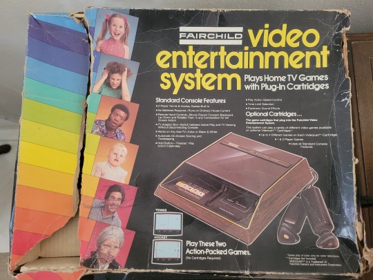
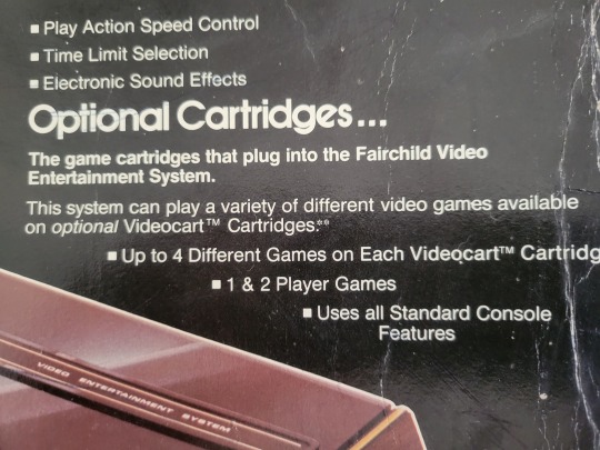
Today’s detour from the vagaries of Surfing video games (still playing, but had a change of plans) involves a piece of gaming history. This fine piece of wood grain adorned set top goodness is from November 1976, released by Fairchild. This is one of the early ones, as it was renamed the “Channel F” (F is for fun) when Atari launched their Video Computer System a little less than a year later. The key is in this feature:
The Fairchild VES was the first system to use ROM cartridges (earlier consoles had enabled folks to use ‘games’ that were really just sets of jumpers inserted into the main console to change into another of the 100 versions of PONG that most of them played). This is notable, as the Chief Engineer for Fairchild at the time was Gerald Lawson (much more info at this link: https://www.google.com/doodles/gerald-jerry-lawsons-82nd-birthday ).
Fairchild only sold about 350,000 units before they called it quits and sold the IP off. Their main product was microprocessors, so this was a bit of a flyer for them. Given the way things exploded for Atari, they came very close to hitting the big time -- anyhoo, the point is not very many of these out in the wild, and most of them need to be acquired as a ‘parts only’ purchase. I suspect this is because the power supplies for most of these (which is hard wired to the console) go bad, or people have no idea how to hook it up to a modern TV to test it.
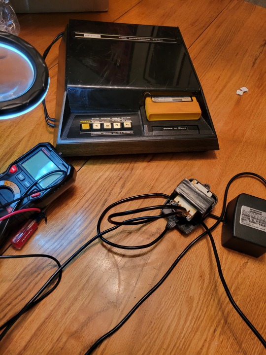
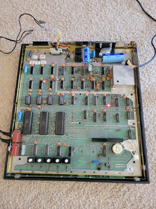
The one I bought was in such a state. Overall it looked pretty good for a 47-year old console, but of course no response when I powered it on. Checking the power block was the first thing I suspected, and sure enough, the output voltages of the power supply where no where near where they were supposed to be, Looking at the block itself - it has 2 different AC inlets....!?
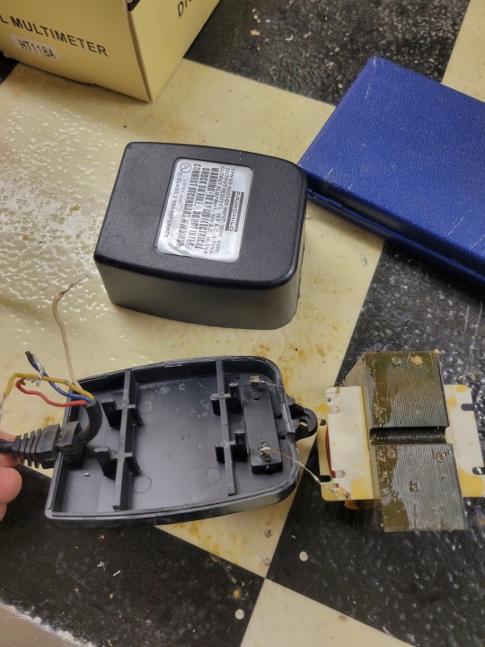
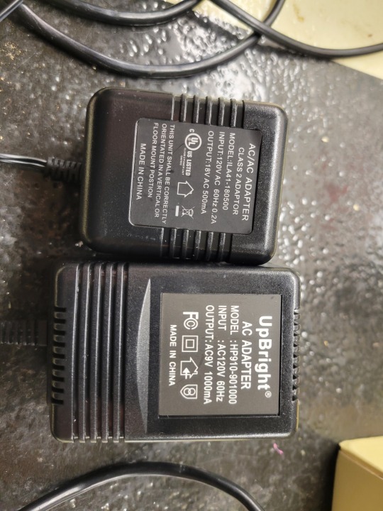
The nice folks at the AtariAge forums have a few threads related to the Fairchild and it’s other worldly counterparts. Sure enough - 15VAC 200mA is one input, and the other is 10VAC 1A. Having no idea how to try and Frankenstein this coil back to life, I went in search of adequate AC-AC adapters to be able to get the unit to power on. Reading through the info out on the net, and looking through the schematics, there are rectifiers and capacitors/voltage regulators that step these two inputs down to 12V and 5 V DC. To be able to connect my new power supplies I needed to open it up - so here we go...!
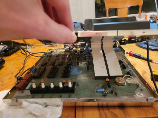
The good news is, everything looked clean. Even the caps looked pretty good, which was surprising as I bet they run a bit hot with all the current being fed into the unit. Look at all that metal shielding! it looks like FCC regs were written with a severe concern over RF interference? Who knows. All I know is that there is the plastic case, and then an entire metal case under the plastic case shrouding all the electronics. Even the power supply is just a simple MOLEX connection through the shielding to another MOLEX inside. Huh. I did manage to locate 2 AC-AC adapters that looked like they would do the trick.
So I wired them up to the unit and powered on - I knew from the Atari Age geniuses that there is a small red power indicating LED on the board (under the cartridge port and also under the shielding over the cartridge port, so I have no idea who it is for) that indicates the 5V power rail is active. I verified this was active:
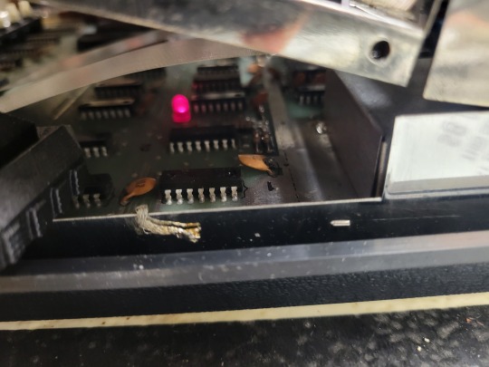
And was thinking I might be done! Too bad - but close - my video output was the green screen.
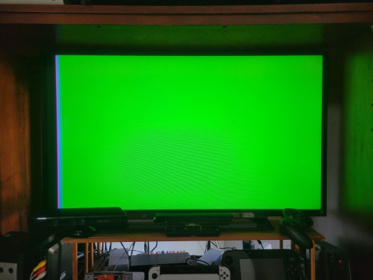
Before I went too much further, I wanted to chase down the power issues. I ended up just disconnecting the MOLEX outside the shielding, and just wiring power right to the wires on the board (power readings on the inlet power cord were all over the place, so I suspect there may have been some wire continuity issues there).
Once I got to this point, I just connected the video out and holy cow! we’re in business.
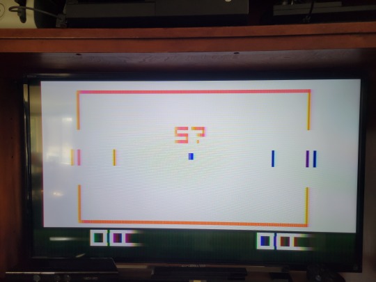
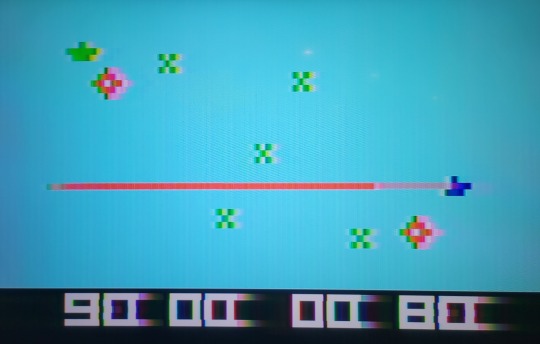
PONG all day and night if we want. Plus a bunch of other games, some of which are terrible but most of which are charming. In a sense, Jerry Lawson taught my sons not to hit on 16 playing black jack. Here’s one of the games (Space War) in action.
One thing that is not great, which was changed for the Channel F II was the sound. For this unit, it comes from the console, and has no volume control. Seeing that most of the videogaming that would have been done on this machine would have been early or late in the day when your parents weren’t using the TV, this one factor may have limited the success. Being able to turn the Atari down low so you could still hear the bleeps and bloops but mom and dad could keep sleeping was key to playing time back in the day.
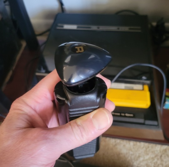
One other item to note is the distinctive but very forward thinking design on the controllers. The knob on the top does all the work -- button presses are pulling up and pushing down. The stick movement is active in all directions, and you can also rotate right and left. It is not very intuitive, but once you play with it for a while the games feel pretty natural. Thinking about how these compare to the Atari joysticks, they have a lot more potential.
All in all not too much trouble, and a fun little project. Very cool that this old beast is now in working order. In retrospect, Fairchild had the right idea, but Atari took it and ran! One has to imagine that if the Channel F had been able to get space invaders, they would likely have done just as well. As it is, they are a bit of a footnote, but I have the footnote running in my house!
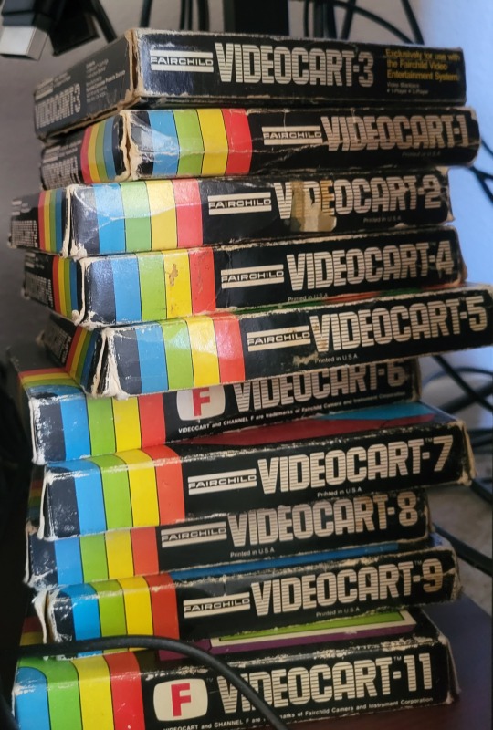
Fun Fact: The dimensions of the Channel F cartridges were set to approximate those of 8-track tapes, which were a thing at the time. They were then colored bright orange/yellow so people wouldn’t mistake Burt Bacharach for a Math Quiz Videocart.
1 note
·
View note
Text
Lupine Publishers | Troubleshooting in Upgrading Procedure: Intraprocedural Percutaneous Transluminal Angioplasty of Great Vessels

Lupine Publishers | Journal of Cardiology & Clinical Research
Abstract
Upgrading procedure is relatively common since indications to cardiac resynchronization therapy (CRT) and implantable defibrillator are increasing. A relatively frequent phenomenon that the operator may encounter is some degree of venous obstruction around the previously implanted leads, which may become completely occlusive. In these situations, upgrading procedure may be challenging and various manoeuvers have been described. We describe a case of intraprocedural percutaneous transluminal angioplasty (PTA) of occlusive stenosis of the innominate vein, performed during an upgrading procedure from bicameral cardiac implantable defibrillator (ICD) to CRT-D.
Keywords: Upgrading; Cardiac resynchronization therapy; Percutaneous transluminal angioplasty; Venous occlusion
Introduction
Cardiac resynchronization therapy is a well-established therapy for patients with severe systolic dysfunction, wide QRS and heart failure despite optimal medical therapy [1]. Moreover, since indications for cardiac resynchronization devices continue to expand, the number of upgrading procedures from previously implanted single- or dual-chamber systems is increasing. In these cases, some degree of venous obstruction is a relatively frequent phenomenon (up to 50%), which may become completely occlusive in 12% of cases [2]. Chronic venous occlusion, mostly asymptomatic, can involve the coronary sinus and its branches as well as central veins, such as the axillary-subclavian or innominate veins. Angioplasty of the coronary sinus is well described in the literature to allow the placement of a left ventricular lead (LV) [3,4]. By contrast, not many data are available on the intra-procedural safety and efficacy of central vessel angioplasty [5,6]. We describe a successful case of angioplasty of a total central venous occlusion to allow LV lead placement during an upgrading procedure to a CRT system.
Case Report
A 69-year-old patient with a clinical history of hypertension, diabetes, prior myocardial infarction, poor EF (30%), and previous percutaneous transluminal coronary angioplasty (PTCA) on the circumflex coronary artery, was referred to our institution for elective replacement of a dual-chamber ICD implanted in July 2008 (ICD Lumos DRT, atrial lead Selox JT 53 and ventricular lead Linox SD 65/16, Biotronik SE. Berlin Germany). On admission, the patient was symptomatic for dyspnea, with a poor functional class (NYHA III), the echocardiogram showed a severely depressed ejection fraction (20%) and the electrocardiogram confirmed a wide QRS duration of 130msec with left bundle branch block. A coronary angiography confirmed the indication to medical therapy in the absence of any target vessel for revascularization. We consequently decided to perform an upgrading procedure to a CRT system. In accordance with our clinical practice, angiography of the axillary and subclavian veins through the ante cubital venous access was performed before the procedure to assess patency of the central veins. The angiogram documented severe stenosis of the axillary vein at the insertion point of the right atrial and ventricular leads into the vessel. The subclavian vein was then directly punctured distally to the sub-occlusive stenosis (behind first rib), to obtain a venous access for the LV lead. Unfortunately, subsequent advancing on the 0.035” guidewire through a sealed 9 Fr introduction sheath (Safe Sheath HLS 1009, Pressure Product, San Pedro, USA) proved unsuccessful owing to another occlusion at the junction between the superior vena cava (SVC) and the innominate vein, where the second shocking coil lead was located. Selective injection of contrast media into the subclavian vein through the introducer confirmed total occlusion of the main vessel and a wide collateral vicarious circulation draining blood into the SVC (Figure 1).
Figure 1: Vein angioplasty procedure. A. Angiography from the subclavian venous access, revealing occlusive venous stenosis of the anonimous trunk. B. Balloon inflated up to 8-10 atm. across the stenosis. C. Restoration of venous patency after angioplasty.
A 0.014” angioplasty guidewire (TERUMO Corporation, Tokyo, Japan) was threaded through the occlusion and then left in the right atrium. An angioplasty balloon (Sterling 6mm x 20mm, Boston Scientific Inc. Natick, USA) was then advanced over the wire to the occlusion and inflated to 6 atm. In order to progressively open the occlusion, we removed the balloon and advanced over the 0.014” wire a multipurpose catheter (Cordis Corporation, Miami, USA) which, thanks to the dotter effect, enabled us to pass through the stenotic tract and to replace the 0.014” with a 0.35” x 200 cm guidewire. Once we had retrieved the MP catheter, a larger angioplasty balloon (Sterling 8 mm x 40 mm, Boston scientific Inc. Natick, USA) was advanced over the 0.35” wire and repeatedly inflated to 10 atm to obtain satisfactory dilation of the subclavian and innominate veins (Figure 1B). A 5-10 cc injection of contrast medium confirmed the re-establishment of flow within the subclavian vein and SVC, with a residual stenosis of 30-40% (Figure 1C). Implantation of the CRT device was then successfully carried out, without complications, by cannulating the coronary sinus through a dedicated delivery system (Attain Command Straight, Medtronic Inc. Minneapolis, USA), placing a 4 Fr dual-unipolar LV lead (Attain Ability 4196- 88 cm, Medtronic Inc. Minneapolis, USA) into a lateral coronary vein and, finally, by connecting the three leads to a CRT-D device (Consulta CRT-D, Medtronic Inc. Minneapolis, USA). The acute LV lead threshold was 1.1 V at 0.5 msec, with no diaphragmatic capture at 10V. The electrical parameters of the right atrial and right ventricular leads were also stable. The additional time required to perform PTA was 15 minutes, plus 3 minutes of fluoroscopy time with an additional 30 cc injection of contrast medium injection. At the 3-month follow-up examination, electrical parameters of atrial, right ventricle and left ventricle leads were stable, and no adverse event was observed.
Discussion
Chronic venous occlusion is not an infrequent finding in patients undergoing implantation procedures. This issue may involve both the coronary sinus and the central venous system. Recognized risk factors for venous obstruction include blood stasis due to venous angulation or kinking, the presence of a central venous line for long-term infusion therapy, hemodialysis, trauma, infection and the presence of pacemaker leads. Heart failure and poor systolic function may facilitate the process [7,8]. The most likely pathogenesis seems to be due to thrombosis, beginning with fibrin deposition over the lead surface and progressive fibrous reaction, with a ring-like fibrosis development around the lead, causing severe stenosis or even total occlusion of the vein [5]. The presence of a second ICD shocking coil, usually located in the superior vena cava, has been associated with increased incidence of venous obstruction [9]. In our case, the occlusion was localized at the junction of the innominate vein with the superior vena cava, where the second shocking coil lead lays for anatomical reasons. Thrombosis and fibrotic reaction were probably favored by the close contact of the heavy coil with the vessel wall at a point where, for hemodynamic reasons, there may be turbulence, thereby predisposing the vessel to occlusive stenosis.
As the stenotic process is usually gradual, a collateral venous network can develop to compensate for the occlusion. Consequently, symptoms or physical signs are rare, and partial or total venous occlusion may be totally asymptomatically, becoming an unexpected finding at the time of implantation. If a new lead needs to be added to the implanted system, the operative strategy may differ considerably according to the physician’s familiarity with the available technical options. The physician can choose among various approaches: an opposite-side approach with subsequent lead tunneling across the thorax [10], an ipsilateral approach performed by means of jugular system cannulation [11], and epicardial placement of the leads through thoracotomy or vein angioplasty [5]. The first option carries several risks, including the development of complete occlusion of both subclavian veins over time, damage to the leads — particularly deleterious in the case of ICD leads - or higher defibrillation threshold in the case of rightside placement of the active can. The jugular system approach may expose the patient to the risk of worsened blood drainage or, in the case of the internal jugular cannulation, even acute serious damage to this important vessel of the neck [12]. Epicardial placement of the leads through thoracotomy has the disadvantage of requiring surgery and general anesthesia.
Our experience showed that angioplasty of the central venous system can be performed in the same session of the upgrading procedure without excessively prolonging the procedural time, thereby avoiding postponing the procedure. We observed no complications, damage or dislocations of the existing leads. Moreover, this approach is less invasive than other alternatives and allows the patency of the contralateral venous system to be preserved. This case also shows that in certain clinical conditions at higher risk of venous occlusion, it is advisable to perform an angiography from ante cubital vein before the procedure, in order to assess the patency and exact location of the great veins. We can hypothesize that incomplete location of the second shocking coil inside the superior vena cava and the lying of the coil across the junction between the innominate vein and superior vena cava may contribute, for hemodynamic reasons, to the development of a marked fibrotic reaction. Eventually, in case of occlusive stenosis of central veins, intraprocedural venoplasty of great vessel seem to be feasible, without postponing the upgrading procedure.
For more lupine publishers open access journal please click on
https://lupinepublishers.us/
For more Journal of Cardiology & Clinical Research articles please click on
https://www.lupinepublishers.com/cardiology-journal/
To know more open access publishers please click on lupine publishers
Follow on Linkedin : https://www.linkedin.com/company/lupinepublishers Follow on Twitter : https://twitter.com/lupine_online
0 notes
Text
Buy Online V-coil Thread Repair Kit
The V-coil Thread Repair Kit makes broken v-threads easy to fix. This kit is of the best quality and price, perfect for maintaining and repairing your appliances and household items. In addition, each kit contains specific sewing supplies for quick & easy mending of your favourite clothes. Buy an Online v-coil thread repair kit in Dubai, UAE at sitcouae.co Visit us: https://www.sitcouae.co/brands/v-coil-thread-insert-systems/
0 notes
Text
High Quality V-Coil Thread Repair Kits
SITCO Trading LLC , we aid you with the best quality products. We are a trusted Exporter, Importer, and Supplier, operating all over the United Arab Emirates and overseas. We export various v-coil thread insert systems that include v-coil thread repair kits, thread repair kits metric, thread repair workshop kits, etc. Visit us: https://www.sitcouae.co/brands/v-coil-thread-insert-systems/
0 notes
Text
High Quality V-Coil Thread Repair kit
Want a quality-driven v-coil thread repair kit? Get company, high-quality standard, easy to handle, no adjustment v-coil thread repair from Saleh Ishaq Trading Company. We offer an exclusive range of thread insert systems like Thread Repair Kits large, UNF, BSF and BSW, BSP, inserting tools, and more. The quality and sturdy packing will be delivered right at the doorstep in the most satisfactory possible condition.
0 notes