#Silicon Controlled Rectifier (SCR) Modules Industry
Explore tagged Tumblr posts
Visit Tumblr Blog
Explore Tumblr blogs with no restrictions, modern design and the best experience.
Last Seen Tumblr Blogs


Fun Fact
The “We are the 99%” Tumblr blog became the slogan for the Occupy Wall Street movement.
Text
Thyristor Manufacturers in India: Powering Efficient Solutions
Thyristors, also known as Silicon-Controlled Rectifiers (SCRs), are integral components in modern electronic and electrical systems. These semiconductor devices are widely used for controlling power flow and ensuring efficiency in various industrial applications. India has emerged as a hub for thyristor manufacturing, thanks to its skilled workforce, advanced manufacturing facilities, and growing demand in sectors like power electronics, industrial automation, and renewable energy.
What Are Thyristors?
Thyristors are semiconductor devices that act as switches, allowing electrical current to flow in one direction when triggered. Their unique capability to handle high voltage and current makes them indispensable in applications such as:
Power conversion and rectification
Voltage regulation in power systems
Motor control in industrial machinery
Light dimming and heating controls
Their robustness and efficiency make them crucial in both consumer electronics and heavy industrial equipment.
India's Thyristor Manufacturing Landscape
India has become a prominent destination for thyristor manufacturing due to its strong engineering expertise, cost-effective production capabilities, and supportive government policies. Thyristor manufacturers in India cater to both domestic and international markets, offering high-quality products that meet global standards.
Key factors driving the growth of thyristor manufacturing in India include:
Industrial Growth: The rapid expansion of sectors such as power generation, electric vehicles, and renewable energy has increased the demand for thyristors.
Technological Advancements: Indian manufacturers are investing in cutting-edge technologies to produce thyristors with higher efficiency and reliability.
Export Opportunities: Indian thyristor manufacturers are gaining recognition globally, exporting their products to Europe, the Middle East, and Asia.
Applications of Thyristors
The versatility of thyristors makes them suitable for diverse applications. Here are some key areas where thyristors are indispensable:
Power Electronics: Thyristors are widely used in AC/DC conversion, voltage control, and power distribution systems.
Renewable Energy: In solar and wind energy systems, thyristors play a critical role in regulating power flow and integrating energy into grids.
Industrial Automation: Thyristors enable precise control of motors and machinery, ensuring efficient and reliable operations.
Transportation: They are used in electric trains and vehicles for power regulation and motor control.
Consumer Electronics: Thyristors are used in devices like air conditioners, refrigerators, and washing machines for efficient energy management.
Leading Thyristor Manufacturers in India
Several companies in India specialize in the design and production of thyristors, offering products tailored to various industrial needs. These manufacturers focus on quality, innovation, and customer satisfaction. Some prominent players include:
Bharat Heavy Electricals Limited (BHEL): Known for producing high-capacity thyristors for industrial applications.
Littelfuse India: Offers a wide range of thyristors for automotive and industrial sectors.
Powersem Semiconductors: Specializes in high-power thyristors for renewable energy systems.
Semikron India: Focuses on power modules and thyristors for industrial and transportation applications.
The Future of Thyristor Manufacturing in India
With the global shift toward renewable energy and energy-efficient technologies, the demand for thyristors is expected to grow significantly. Indian manufacturers are well-positioned to capitalize on this trend by:
Expanding Production Capacities: Increasing manufacturing output to meet rising domestic and international demand.
Investing in R&D: Developing advanced thyristors with improved performance and reliability.
Collaborating with Global Partners: Strengthening partnerships to enhance technological expertise and market reach.
Conclusion
Thyristors are vital components driving efficiency and reliability in modern electrical and electronic systems. The growing demand for these devices across various industries underscores their significance. Thyristor manufacturers in India are at the forefront of this transformation, offering world-class products that cater to diverse applications.
As India continues to evolve as a global manufacturing hub, the thyristor industry is poised for sustained growth, contributing to the nation’s industrial progress and global competitiveness. Whether for powering renewable energy systems or optimizing industrial machinery, Indian thyristor manufacturers are empowering solutions for a sustainable future.
0 notes
Text
Semiconductor Parts in the Aircraft Industry: Enhancing Safety and Efficiency
In the fast-paced world of aviation, where precision, reliability, and safety are paramount, the role of semiconductor components cannot be overstated. These tiny yet powerful devices form the backbone of modern aircraft systems, enabling critical functions that ensure smooth operations from takeoff to landing. Let’s explore some key semiconductor parts and their contributions to the aerospace industry.
Diodes: Directing Current Flow with Precision
Diodes are fundamental semiconductor components in aircraft systems. They primarily serve to control the direction of electric current, ensuring that electricity flows in only one direction. In aviation, diodes are used in various applications such as power supplies, switching circuits, and voltage regulation. They play a crucial role in protecting sensitive electronic equipment from reverse voltage spikes and ensuring stable operation of essential systems.
Triacs: Controlling AC Power
Triacs are semiconductor devices that enable the precise control of AC (alternating current) power. They are extensively used in aircraft for applications such as dimming lights, controlling heating elements, and managing motor speed. Triacs allow for efficient and reliable adjustment of power levels, contributing to energy savings and operational flexibility in onboard systems.
Transistors: Switching and Amplification
Transistors are perhaps the most versatile semiconductor devices found in aircraft electronics. They serve dual roles as switches and amplifiers, crucial for controlling signals and power in avionics systems. Transistors enable efficient switching of digital signals, amplification of weak signals from sensors, and modulation of radio frequencies in communication systems. Their reliability and performance under varying environmental conditions make them indispensable in aerospace applications.
Bridge Rectifiers: Converting AC to DC
Bridge rectifiers are semiconductor assemblies used to convert alternating current (AC) into direct current (DC). In aircraft, where numerous systems and equipment rely on DC power, bridge rectifiers play a critical role in converting power from generators and other AC sources into a usable form. They ensure a steady and reliable supply of DC voltage for avionics, navigation instruments, communication devices, and other essential onboard systems.
SCRs (Silicon-Controlled Rectifiers): Ensuring Power Regulation
SCRs are semiconductor devices used for precise control of large electrical currents. They excel in applications requiring high current regulation and are commonly found in aircraft power management systems. SCRs ensure efficient power distribution, voltage regulation, and protection against overcurrent conditions. Their robust design and ability to handle high-power loads make them essential for maintaining the reliability and safety of critical aircraft systems.
Challenges and Innovations in Semiconductor Technology
The aerospace industry poses unique challenges for semiconductor technology. Aircraft operate in extreme environmental conditions, including wide temperature ranges, high altitude, and electromagnetic interference. Semiconductor manufacturers continually innovate to develop components that meet stringent aerospace standards for reliability, durability, and performance under such demanding conditions.
Advanced materials and manufacturing techniques are key to producing semiconductor parts capable of withstanding the rigors of flight. Specialized coatings, ruggedized designs, and enhanced thermal management techniques ensure that semiconductor devices maintain optimal performance throughout their operational lifespan.
Future Directions and Beyond
Looking forward, semiconductor technology will continue to drive innovation in the aerospace industry. Advancements in materials science, miniaturization, and integration will enable more compact and energy-efficient aircraft systems. The ongoing development of smart sensors, artificial intelligence, and connectivity solutions will further enhance aircraft performance, safety, and passenger comfort.
In conclusion, semiconductor components are integral to the evolution of aviation technology, enabling aircraft to operate more efficiently, safely, and reliably. As aerospace engineering continues to push boundaries, semiconductor innovation will play a central role in shaping the future of air travel, ensuring that aircraft remain at the forefront of technological advancement in the 21st century and beyond.
#semiconductors#aircraft parts#aviation industry#aerospace#aviation parts#aerospace industry#industrial parts supplier
1 note
·
View note
Text
How Are Thyristor Modules Used in AC Motor Control?
Thyristor modules, also known as SCR (Silicon Controlled Rectifier) modules, are semiconductor devices that can switch high voltages and currents with very high efficiency. They work by controlling the flow of current to the motor, allowing precise adjustments to its speed and torque.
In AC motor control, thyristor modules are typically used in conjunction with other components such as control circuits, sensors, and feedback mechanisms. The thyristor module acts as a switch, turning the motor on and off at the right times to achieve the desired speed and direction.
One of the key advantages of using thyristor modules in AC motor control is their ability to handle high currents and voltages, making them ideal for industrial applications where heavy-duty motors are used. Additionally, thyristor modules offer precise control over the motor's speed and direction, allowing for smooth and efficient operation.
Another benefit of using thyristor modules in AC motor control is their reliability. Unlike mechanical switches, thyristor modules have no moving parts, which means they are less prone to wear and tear. This makes them an excellent choice for applications where reliability is critical.
0 notes
Text
Insights Into The Power Electronics Market Size 2022-2028 Forecast Period
The analysis covers market drivers, constraints, challenges, strategic expansions, market size and share, development prospects, and threats. A complete definition of the industry and its important segments, as well as an analysis of the business vertical, are included in the most recent study on the Power Electronics Market. The industry is growing, according to the report, as a result of technical advancements.
Book Your Free Sample Report @ https://www.snsinsider.com/sample-request/1246
The report also includes segmentation data, such as type, industry, and channel sectors, as well as market size data in terms of both volume and value, for each segment. Manufacturers must grasp the lucrative segments of the Power Electronics market where these major firms are investing their efforts, therefore information on notable industry participants is also provided.
MARKET SEGMENTATION:
BY WAFER TYPE
Gallium Nitride
Silicon Carbide
Silicon
Others
BY COMPONENT
Thyristor
Gate Turn-Off Transistor (GTO)
Silicon Controlled rectifier (SCR)
Static Switches
MCT (MOS-Controlled Thyristor)
AC/DC Converter
MOSFET
Others
BY WAFER SIZE
450mm
200mm
300mm
150mm
BY APPLICATION
Defense and Aerospace
Utilities and Energy
Transportation
Consumer Electronics
Telecommunications and IT
Automotive
Industrial
Others
BY DEVICE
Discrete
IC
Module
COVID-19 Impact Analysis
The report also considers market growth influences, such as the current COVID-19 outbreak. The COVID-19 pandemic, according to the study, had a significant impact on the Power Electronics industry's supply chain, demand, trends, and general dynamics. It also forecasts market expansion following COVID-19.
Key Influencers for Power Electronics Market
The study goes into great detail regarding the market's characteristics and factors that contribute to its success. The industry's growth is fueled by the ongoing efforts of significant corporations to produce new goods and technologies. In addition, the industry is seeing a flurry of strategic collaborations and efforts that are expanding the market's scope.
Regional Dynamics
To provide a thorough view of the market, the regional research sections also provide a country-by-country study. The regional split of the market is indicated by the Power Electronics market analysis in places where the market has already established itself as a leader. It also looks at import/export studies, supply and demand dynamics, regional trends and demands, and the presence of major actors in each region's production and consumption ratios.
Competitive Scenario
The research includes a complete evaluation to give the reader a better understanding of the market's competitive environment. The study also includes information on each player's revenue, gross profit margin, financial status, market position, product portfolio, and other pertinent parameters. The report also includes a complete SWOT analysis and a Porter's Five Forces analysis. This section focuses on the major market players' initiatives and advancements in order to establish a strong presence.
The Power Electronics market analysis also includes information on mergers and acquisitions, joint ventures, collaborations, partnerships, and agreements to provide you a better picture of the industry. This section is ideal source of input for market players to revisit their strategic positions.
Buy This Exclusive Report @ https://www.snsinsider.com/checkout/1246
Table Of Contents
1. Introduction
1.1 Market Definition
1.2 Scope
1.3 Research Assumptions
2. Research Methodology
3. Market Dynamics
3.1 Drivers
3.2 Restraints
3.3 Opportunities
3.4 Challenges
4. Impact Analysis
4.1 COVID 19 Impact Analysis
4.2 Impact Of Ukraine-Russia War
5. Value Chain Analysis
6. Porter’s 5 Forces Model
7. PEST Analysis
8. Global Power Electronics Market Segmentation, By Wafer Type
8.1 Gallium Nitride
8.2 Silicon Carbide
8.3 Silicon
8.4 Others
Contact Us:Akash AnandHead of Business Development & [email protected]: +44 20 8144 2758
0 notes
Text
What is a power module and what are its uses?
Several Power module typically power semiconductor devices, are physically contained by a Power module or power electronic module. These power semiconductors, also known as "dies," are commonly soldered or sintered onto a power electronic substrate, which also acts as a carrier for the power semiconductors and as a source of electrical insulation when necessary. Power packages offer a higher power density and are frequently more dependable when compared to discrete power semiconductors in plastic housings like TO-247 or TO-220.
Uses
Power modules are used in AC-DC power supplies, welder power supplies, uninterruptible power supplies, embedded motor drives, industrial motor drives, and embedded motor drives.
Inverters for renewable energy sources including wind turbines, solar panels, tidal power plants, and electric cars also frequently use power modules (EVs).
Electric vehicles and other electric motor controllers, appliances, power supplies, electroplating machinery, medical equipment, battery chargers, AC to DC inverters and converters, power switches, and welding equipment are just a few examples of the many applications for power modules.
Types
Transistors and diodes are frequent components of power modules. Some of the most typical switching components found in power modules include silicon controlled rectifiers (SCRs), insulated-gate bipolar transistors (IGBTs), and metal oxide semiconductor field-effect transistors (MOSFETs). Transistors are combined in some power modules to create widely used designs, such as half-bridge and H-bridge configurations. With these setups, a single voltage power source can simply change the direction of current flowing through a motor. For inverting applications—which convert direct current electricity into alternating current—more sophisticated modules with up to six transistors are also available. These applications are frequently found in renewable or "green" energy systems.
Various options include single, dual, or other configurations for diode power modules. Diodes are frequently used in bridge rectifiers, which transform alternating current into direct current electricity. For single-phase alternating current, a bridge rectifier of four diodes can be used; for three-phase current, a bridge rectifier of six diodes can be used. Power modules conveniently offer single-phase and three-phase bridge rectifiers for quick installation and repair.
Power modules have continued to advance, just like other technologies, in order to more effectively address technical difficulties and make use of them. Some of the most recent advancements in power module technology are intelligent power modules. Typically, these modules have an IGBT with additional control and protection circuitry. The driving circuitry for switching the IGBT and gate drive logic is provided by the control circuitry, enabling quick on and off. High temperatures, excessive current, short circuits, and under voltage circumstances can all cause issues that can be avoided by using intelligent power module protective circuitry.
0 notes
Text
[EEE] ELECTRICAL Engineering Multiple Choice Questions and Answers
Below are the list of all Electrical Engineering Multiple Choice Questions and Answers for EEE students. also we can provide Electrical objective questions books & Interview questions. CLICK HERE ----> EEE INTERVIEW QUESTIONS
Electrical Engineering Questions with Answers pdf :-
1. Current Electricity 2. Network Theorems 3. Electrostatics 4. Magnetism and Electromagnetism 5. Magnetic Circuit 6. Electromagnetic Induction 7. Electrolysis and Storage of Batteries 8. A.C. Fundamentals, Circuits and Circuit Theory 9. D.C. Generators 10. D.C. Motors 11. Transformers 12. Polyphase Induction Motors 13. Single Phase Induction Motors 14. Synchronous Motors 15. Rectifiers and Converters 16. Power Plant Engineering (Generation of Electrical Power) 17. Economics of Power Generation 18. Transmission and Distribution 19. Switchgear and Protection 20. Cables 21. Electrical Engineering Materials 22. Electrical Machine Design 23. Measurement and Instrumentation 24. Control Systems 25. Electric Traction 26. Industrial Drives 27. Heating and Welding 28. Series-parallel Circuits 29. Passive Filters 30. Ohm's Law 31. DIGITAL ELECTRONICS 32. Quantities and Units 33. Series Circuits 34. Branch, Loop and Node Analyses 35. Alternating Current and Voltage 36. Inductors 37. RC Circuits 38. RLC Circuits and Resonance 39. Three-Phase Systems in Power Applications 40. Time Response of Reactive Circuits 41. Circuit Theorems and Conversions 42. OP-AMP Circuits 43. ANALOG ELECTRONICS 44. SEMICONDUCTOR THEORY 45. SEMICONDUCTOR DIODE 46. TRANSISTORS 47. TRANSISTOR BIASING 48. SINGLE STAGE TRANSISTOR AMPLIFIERS 49. Multi-Stage Transistor Amplifiers 50. TRANSISTOR AUDIO POWER AMPLIFIERS 51. Operational Amplifier 52. HYBRID PARAMETERS 53. ELECTRONIC INSTRUMENTS 54. INTEGRATED CIRCUITS 55. POWER ELECTRONICS 56. SCR (Silicon Controlled Rectifiers) 57. FET – Field Effect Transistors 58. Solid-State Switching Circuits 59. Regulated D.C. Power Supply 60. Modulation and Demodulation 61. Transistor Tuned Amplifiers 62. Oscillators 63. Amplifiers with Negative Feedback 64. Parallel Circuits 65. EARTHING or GROUNDING CLICK HERE--->BASIC ELECTRONICS Questions and Answers ****** Dear Electrical students, We provide Basic Electrical Engineering multiple choice questions and answers with explanation & EEE objective type questions mcqs books pdf free download here. these are very important & Helpful for campus placement test, semester exams, job interviews and competitive exams like GATE, IES, PSU, NET/SET/Jhttpss://en.wikipedia.org/wiki/Electrical_engineeringRF, UPSC and diploma.
ELECTRICAL Engineering Mcqs Especially we are prepare for the Electrical Engineering freshers and professionals, these model questions are asked in the online technical test, Quiz and interview of many companies. These are also very important for your lab viva in university exams like JNTU, Andhra,OU,Anna university,Pune,VTU,UPTU,CUSAT etc. Electrical Engineering objective type Questions pdf free download :- Read the full article
0 notes
Text
N1-§2 What is the Structure of a Solid-State Relay?

The solid-state relays are four-terminal active devices, two of the four terminals are input control terminals, and the other two terminals are output control terminals. Although the types and specifications of SSR switches are numerous, their structures are similar and consist mainly of three parts (as shown in Figure 2.1): Input Circuit (Control Circuit), Drive Circuit, and Output Circuit (Controlled Circuit).
Input Circuit:
The Input Circuit of the solid state relay, also called control circuit, provides a loop for the input control signal, making the control signal as a trigger source for the solid state relay. According to different input voltage types, the input circuit can be divided into three types, DC input circuit, AC input circuit and AC/DC input circuit.
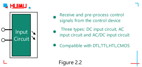
The DC input circuit can be further divided into Resistive Input Circuit and Constant Current Input Circuit. 1) The Resistive Input Circuit, whose input current increases linearly with increasing input voltage, and vice versa. If the control signal has a fixed control voltage, the resistor input circuit should be selected. 2) The Constant Current Input Circuit. When the input voltage of the constant current input circuit reaches a certain value, the current will no longer increase obviously as the voltage increases. This feature allows the use of a constant current input solid state relay over a fairly wide input voltage range. For example, when the voltage variation range of the control signal is kind of large (e.g., 3~32V), the DC solid state relay with constant current input circuit will be recommended to ensure that the DC solid-state relay can work reliably over the entire input voltage range. Some of these input control circuits have positive and negative logic control, inverting and other functions, as well as the compatibility of logic circuits. Thus, solid state relays can be easily connected to TTL circuits (Transistor-Transistor Logic circuits), CMOS circuits (Complementary Metal Oxide Semiconductor circuits), DTL circuits (Diode-Transistor Logic circuits), and HTL circuits (High Threshold Logic circuits). At present, DTL has been gradually replaced by TTL, and HTL has been replaced by CMOS. And if the Pulse Width Modulated signal (PWM) is used as input signal, the ON/OFF switching frequency of the AC load supply should be set to less than 10Hz, or the output switching rate of the output circuit of the AC SSR cannot keep up with it.
Drive Circuit:
The driving circuit of solid state relay includes three parts: Isolation Coupling Circuit, Function Circuit and Trigger Circuit. However, according to the actual needs of solid-state relay, only one/two of these parts may be included.

1. Isolated Coupling Circuit:
The isolation and coupling methods for I/O circuits (Input / Output circuit) of solid-state relays currently use two ways, Optocoupler Circuits and High Frequency Transformer Circuits. 1) Optocoupler (also called photocoupler, optical coupler, opto-isolator, or optical isolator) is opaquely packaged with an infrared LED (Light-Emitting Diode) and an optical sensor to achieve isolated control between "control side" and "load side", because there is no electrical connection or physical connection between the " Light emitter " and the " Light sensor" except the beam. The types of “source-sensor” combinations normally include: "LED-Phototransistor" (Phototransistor Coupler), "LED-Triac" (Phototriac Coupler), and "LED-Photodiode array" (the stack of photodiodes is used to drive a pair of MOSFETs or an IGBT). 2) The high frequency transformer coupling circuit uses a high frequency transformer to convert the control signal at the input to the drive signal at the output. The detail process is, the input control signal produces a self-oscillating high frequency signal that will be transmitted through the transformer core to the transformer secondary, and after processing by the detection/rectification circuit and the logic circuit, the signal will eventually become the drive signal to drive the trigger circuit.
2. Functional Circuit:
The functional circuit may include various functional circuits, such as detection circuit, rectifier circuit, zero-crossing circuit, acceleration circuit, protection circuit, display circuit, etc.
3. Trigger Circuit:
The trigger circuit is used to provide a trigger signal to the output circuit.
Output Circuit:
The output circuit of the solid-state relay is controlled by a trigger signal to enable on/off switching of the load power supplies.
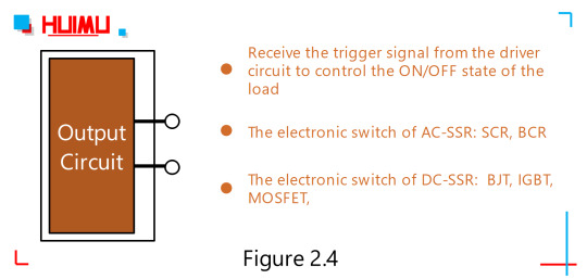
The output circuit is mainly composed of an output component (chip) and an absorption loop (which acts as a transient suppressor), and sometimes includes a feedback circuit. Up to now, the output component of solid state relays mainly include:Bipolar Junction Transistor(Bipolar Transistor or BJT, which divided of two types, PNP and NPN), Thyristor (Silicon Controlled Rectifier or SCR), Triac (Bi-directional Triode, Bi-directional thyristor, Bi-directional Controlled Rectifier or BCR), Metal-Oxide-Semiconductor Field-Effect Transistor (MOSFET), Insulated Gate Bipolar Transistor(IGBT), Silicon-Carbide MOSFET (SIC MOSFET, a kind of wide bandgap transistor with the industrial grade highest operating junction temperature of 200°C, low power consumption and compact size), and so on. The output circuit of the solid state relay can be divided into three types: DC output circuit, AC output circuit and AC/DC output circuit. The DC output circuit typically uses bipolar component (such as IGBT or MOSFET) as the output component, and the AC output circuit usually uses two Thyristors or one Triac as the output component.
0 notes
Text
Global Silicon Controlled Rectifier (SCR) Modules Market 2017 - Infineon Technologies, Microsemiconductor
Global Silicon Controlled Rectifier (SCR) Modules Market 2017 – Infineon Technologies, Microsemiconductor
Global Silicon Controlled Rectifier (SCR) Modules Market 2017Research Report analyses a Market Regions, Product Categories, with Sales, Market Revenue, Product cost, Silicon Controlled Rectifier (SCR) Modules market Share and Growth trends, focusing on leading Silicon Controlled Rectifier (SCR) Modules industry players, market size, demand and supply analysis, consumption volume, Forecast 2017 to…
View On WordPress
#Silicon Controlled Rectifier (SCR) Modules#Silicon Controlled Rectifier (SCR) Modules Industry#Silicon Controlled Rectifier (SCR) Modules Market#Silicon Controlled Rectifier (SCR) Modules Market Share
0 notes
Text
Design and implementation of weighing control instrument for Raymond Mill feeder
The development of Raymond Mill in talc and other powder industries will be mainly in the direction of high reliability, energy saving, precision, automatic working condition monitoring and automatic control. It can adopt SCR power supply, AC frequency conversion speed regulation, grease centralized lubrication, shock absorption and other measures, and face mask machine has working condition monitoring and microcomputer automatic control of Raymond mill. In this paper, in order to ensure the quality of talcum mill and improve the production efficiency, an automatic feeding control system based on PID algorithm is designed. The product realizes the uniform supply of materials, so as to make the mill in the best load operation, prevent the blocking and idling phenomenon, reduce the mill failure and improve the quality of grinding powder This paper mainly introduces the working principle of Raymond mill and discusses the detailed design method in the automatic feeding control design process of Raymond mill and the matters needing attention in the actual design; the product development results have been put into use, and the operation is simple, the function is complete and the performance is reliable, which has been widely praised by users.
The working principle of Raymond mill is composed of main engine, classifier, blower, bucket elevator, electromagnetic vibration feeder, storage hopper, jaw crusher, pipeline system and electric control cabinet. The working principle block diagram is shown in Figure 1.
The starting of Raymond mill must be carried out according to the following steps:
(1) start the hoist;
(2) start the crusher, and the material can be crushed after starting,(3) start the classifier and adjust it to the required speed according to the product fineness;
(4) start the blower and open the air inlet valve after starting;
(5) start the main engine, in order to make the grinding roller and ring wear less and avoid excessive vibration of the machine, the idling time of the main engine should not be too long, that is, no more than 2 minute. In order to avoid excessive loading of the main engine, excessive materials are not allowed in the main engine during starting;
(6) start the vibration feeder and adjust the amplitude as required;
the sequence of shutdown is to stop feeding, then stop the main engine, fan and finally stop the classifier. In order to ensure the normal operation of Raymond mill, reduce mill failure and improve the quality of grinding powder, Raymond mill must be started in accordance with the above sequence, and the mill load should be monitored at any time to prevent blocking and idling.
2. The design and implementation of automatic feeding control
2.1 design scheme
in order to realize automatic feeding of Raymond mill, the first work to be completed is to detect the working load of the mill in real time, and automatically increase or decrease the feeding according to the load through the microcomputer processing and analysis control. The main machine current or fan current of Raymond mill can be used to reflect the mill load. After practical investigation, the following conclusions can be obtained: 1) the range of main machine current conversion is very large, and the current jitter at the working point is very large, which can not accurately reflect the working load of the mill. ② The range of fan current conversion is also comparedHowever, at that time, the fan current was very sensitive when the main engine was loaded. Once the main engine was overloaded, the fan current would quickly drop (Note: the fan current changes in the opposite direction with the load). Therefore, in order to achieve more accurate automatic feeding, this design uses the fan current as the input signal, and uses the mature PID control algorithm to drive the feeder, forming a complete closed-loop system, as shown in Figure 2.
2.2 fan current sampling
the dynamic range of fan current of Raymond fan is 0-150a, and the change of fan indirectly reflects the load of main engine. In order to ensure accurate response to the load of the main engine, the sampling circuit should ensure that the current of 2A can be identified by the sampling circuit. Therefore, the fan current designed should not only ensure a large dynamic range of current, but also ensure a high detection sensitivity. In view of the above requirements, AC sampling method is adopted. The current (0-5A) of fan current secondary coil is taken, and then the current value is sampled by compact current transformer. In order to facilitate the acquisition of current by single chip microcomputer, the output bipolar AC signal of current transformer is added with a certain bias, and then it is collected by ad to the internal of single chip microcomputer. In order to detect the effective value of the current, this design realizes a software peak value protector in the MCU, collects the signal greater than one cycle, finds out the maximum value after a collection, converts the maximum value into the effective value, and finally converts it into the fan current value according to a certain proportion. front endThe acquisition circuit is shown in Figure 3. The acquisition scheme is tested and verified on the actual product, which can identify the current of 1a and meet the design requirements.
2.3 output execution unit design
(1) the principle of vibration feeder
the current of electromagnetic coil of feeder is rectified by single-phase half wave. When the coil is connected, there is a pulse electromagnetic force between the armature and the iron core, which attracts each other, and the tank moves backward, The main spring of the exciter deforms and stores a certain potential energy. There is no current passing through the negative half circle coil, and the electromagnetic force disappears. The main spring releases energy and makes the armature and iron core move forward from the slot body in the opposite direction. Therefore, the electromagnetic vibration feeder vibrates 3000 times per minute at the frequency of AC power supply, Because of the angle between the bottom plane of the tank and the action line of the exciting force, the material in the tank moves forward continuously along the trajectory of the parabola. The feeding quantity of electromagnetic vibration feeder can be controlled by adjusting the rectifier voltage. The feeder is powered by silicon controlled rectifier. The output voltage can be controlled by changing the conduction angle of thyristor. According to the use conditions, different signals can be used to control the size of the thyristor conduction angle to achieve the purpose of automatic quantitative feeding.
(2) Vibration feeder drive design
this part of the design is mainly to use SCM resources to achieve phase modulation function, so as to drive the unidirectional silicon controlled rectifier voltage to control the vibration feeder. In the design, the external part of a single chip is usedThe interrupt port captures the AC zero crossing point, and then turns on the phase-shifting timer. The initial value of the timer is converted into the phase-shifting angle of thyristor. Changing the initial value of the timer can realize the phase-shifting of any value. The output controller signal is isolated by optocoupler and added to the control pole of SCR.
(3) The design of controller software includes AD acquisition control, output control unit, display unit, user key control unit and PID control algorithm. The operation flow chart of the controller software is shown in Figure 4. After power on, the program detects whether the key is pressed. The user can set the working current value, and then collect the primary current value. When the PID control time is up, the PID algorithm is executed to update the output value. External interrupt service program is mainly used to detect AC zero crossing and realize phase modulation function.
3 conclusion
this paper analyzes the working principle of Raymond mill and vibration feeder, and elaborates the design scheme of weighing control instrument of feeder, as well as the key technology of controller. The automatic feeding controller designed in this paper has been put into production. Its operation is simple, its function is complete, and its performance is stable. It has been widely praised by users.
this article originates from the network reprint. If there is any infringement, please contact to delete it
0 notes
Text
Silicon Controlled Rectifier (SCR) Market Growth, Trends, And Forecast (2019 – 2026)
The recent report, Silicon Controlled Rectifier (SCR) market fundamentally discovers insights that enable stakeholders, business owners and field marketing executives to make effective investment decisions driven by facts – rather than guesswork. The study aims at listening, analyzing and delivering actionable data on the competitive landscape to meet the unique requirements of the companies and individuals operating in the Silicon Controlled Rectifier (SCR) market for the forecast period, 2019 to 2026.
Request for Sample Copy of Silicon Controlled Rectifier (SCR) Market Report@ https://www.marketexpertz.com/sample-enquiry-form/27432
Scope of the Report: The research methodologies used for evaluating the Silicon Controlled Rectifier (SCR) market are inventive and also provides enough evidence on the demand and supply status, production capability, import and export, supply chain management and investment feasibility. The investigative approach applied for the extensive analysis of the sale, gross margin and profit generated by the industry are presented through resources including tables, charts, and graphic images. Importantly, these resources can be easily integrated or used for preparing business or corporate presentations.
Market Segment on the basis of manufacturers, the report covers:
· Infineon Technologies
· Microsemiconductor
· STMicroelectronics
· IXYS
· Vishay
· Semikron
· Crydom
Market split by Type, can be divided into:
· Unidirectional SCR Modules
· Bidirectional SCR Modules
Market split by Application, can be divided into:
· Electronics
· Power Industry
· Communcations
· Other
Buy Silicon Controlled Rectifier (SCR) Market Report @ https://www.marketexpertz.com/checkout-form/27432
Estimating the potential size of the Silicon Controlled Rectifier (SCR) industry: Industry experts conducting the study further estimate the potential of the Silicon Controlled Rectifier (SCR) industry. Such information is important for firms looking to launch an innovative service or product on the market. Industry experts have measured the total volume of the given market. Researchers have calculated the industry in terms of sales by the competitors and end-user – customers. Data on the entire size of the Silicon Controlled Rectifier (SCR) market for a particular product or a service for the forecast period, 2019 to 2026 covered in the report makes it valuable. This information reveals the upper limit of the Silicon Controlled Rectifier (SCR) industry for a specific product or service.
Market share: The report discovers market’s total sale that is generated by a particular firms over a time period. Industry experts calculate share by taking into account the product sales over a period and then dividing it by the overall sales of the Silicon Controlled Rectifier (SCR) industry over a defined period. Subject matter experts further use this metric to offer a general idea of the share and size of a firm and its immediate rivals. By providing an in-depth knowledge of the position a company as well as an entrepreneur holds in the Silicon Controlled Rectifier (SCR) market
The research provides answers to the following key questions:
· What is the estimated growth rate of the Silicon Controlled Rectifier (SCR) market for the forecast period 2019 - 2026? What will be the market share and size of the industry during the estimated period?
· What are prime factors expected to drive the Silicon Controlled Rectifier (SCR) industry for the estimated period?
· What are the major market leaders and what has been their winning strategy for success so far?
· What are the significant trends shaping the growth prospects of the Silicon Controlled Rectifier (SCR) market?
· What are the key challenges expected to restrict the progress of the industry for the forecast period, 2019 - 2026?
· What the opportunities product owners can bank on to generate high profits?
Read More @ https://www.marketexpertz.com/industry-overview/silicon-controlled-rectifier-scr-market
About Us: Planning to invest in market intelligence products or offerings on the web? Then marketexpertz has just the thing for you - reports from over 500 prominent publishers and updates on our collection daily to empower companies and individuals catch-up with the vital insights on industries operating across different geography, trends, share, size and growth rate. There's more to what we offer to our customers. With marketexpertz you have the choice to tap into the specialized services without any additional charges.
Contact Us: John Watson Head of Business Development Market Expertz | Web: www.marketexpertz.com Direct Line: +1-800-819-3052 E-mail: [email protected] News: https://www.marketexpertz.com/market-news
#Silicon Controlled Rectifier (SCR) Market#Silicon Controlled Rectifier (SCR) Market Size#Silicon Controlled Rectifier (SCR) Market Share#Silicon Controlled Rectifier (SCR) Market Trends#Silicon Controlled Rectifier (SCR) Market Growth#Silicon Controlled Rectifier (SCR) Market Analysis#Silicon Controlled Rectifier (SCR) Market Forecast
0 notes
Text
What are The Different Types of Variable Frequency Drives Used for Industrial Applications
Changing the frequency for speed control is one of the most essential tasks associated with AC induction motors, which is effectively achieved with Variable Frequency Drive (VFD). This is one the basic reasons that helps industries and mechanic professionals to ideally ensure speed control and achieve significant power output.
VFDs empower controlling of speed with full torque from 0 rpm up to the full rated speed, as well as beyond when the torque is reduced. Such is the impact of variable frequency drive that they have become an integral part of AC motor integration in different industries. When we are talking about VFDs, it is necessary to understand the different types of common drives provided by variable frequency drive manufacturers:
1. Current Source Inversion (CSI)
CSI variable frequency drives are commonly used across in industrial power and signal processing applications. These drives provide clean current waveform and are highly effective where there is a need to flow power back to the power supply from the motor because of regenerative power capability (the only type of VFDs providing such ability).
2. Voltage Source Inversion (VSI)
VSI works on the voltage inversion concept, but have not been used much across industrial applications because of poor power factor. These drives also do not provide capability of regenerative power and when runs at below 6 Hz may lead to motor cogging.
3. Pulse-Width Modulation (PWM)
The most common and widely used VFD across industries, PWM provides high-end efficiency of simulating sinusoidal wave utilising different length voltage pulses. The drives provides the most ideal solution and advantages with higher efficiencies, low cost input, no motor cogging and having a fixed DC bus voltage allows PWM to render terrific input power factor. To achieve perfect sinusoid the pulses are timed. Silicon-Controlled Rectifiers (SCRs) or Insulated Gate Bipolar Transistor (IGBT), both work well to generate the ideal voltage pulse.
Primarily VFDs ensure high-end speed control to ensure efficient maintenance of connected load at the necessary speed, along with enhancing efficient energy utilisation. It is necessary to understand your industrial application requirement and process, coupled with VFDs working fully when looking for single phase AC motor speed control or so.
#Single phase ac motor speed control#Variable frequency drive manufacturers#Variable frequency drive
0 notes
Text
Silicon Controlled Rectifier Modules Market Share Overview - Reports Monitor
Geographically, this report splits the United States market into seven regions:
The West
Southwest
The Middle Atlantic
New England
The South
The Midwest
with sales (volume), revenue (value), market share and growth rate of Silicon Controlled Rectifier (SCR) Modules in these regions, from 2012 to 2022 (forecast).
Browse Complete Report @ https://www.reportsmonitor.com/united-states-silicon-controlled-rectifier-scr-modules-market-report-2017
United States Silicon Controlled Rectifier (SCR) Modules market competition by top manufacturers/players, with Silicon Controlled Rectifier (SCR) Modules sales volume, price, revenue (Million USD) and market share for each manufacturer/player; the top players including
Infineon Technologies
Microsemiconductor
STMicroelectronics
IXYS
Vishay
Semikron
Crydom
Request Sample Copy @ https://www.reportsmonitor.com/request-sample/?post=98595
On the basis of product, this report displays the sales volume, revenue, product price, market share and growth rate of each type, primarily split into
Unidirectional SCR Modules
Bidirectional SCR Modules
To enquire about this report visit https://www.reportsmonitor.com/make-enquiry/?post=98595
On the basis on the end users/applications, this report focuses on the status and outlook for major applications/end users, sales volume, market share and growth rate of Silicon Controlled Rectifier (SCR) Modules for each application, including
Electronics
Power Industry
Communcations
Other
Browse Similar Semiconductor and Electronics Industry Reports
About Us
Reports Monitor is a platform for companies looking to meet their market research and business intelligence requirements. Our aim is to change the dynamics of the Market Research industry by providing quality intelligence backed by data. Your requirement for market forecasting is fulfilled by our exclusive quantitative and analytics driven intelligence. We have a vast collection of reports, covering maximum industries worldwide. Our process is meticulously planned and executed in order to use maximum resources and explore the market for getting genuine insights. The prime focus is to get reliable data, Decision makers can now rely on our distinct data gathering methods to get factual market forecasting and detailed analysis.
Contact Us
Jay Mathews
Direct: +1 513 549-5911
Email: [email protected]
Website: http://www.reportsmonitor.com
Follow Us
LinkedIn: https://www.linkedin.com/company/reports-monitor
Facebook: https://www.facebook.com/ReportsMonitor
Twitter: https://twitter.com/reportsmonitor
Google Plus: https://plus.google.com/u/0/104187516885663390925
Youtube: https://www.youtube.com/channel/UCW8_Fb1CyDrHQumP5LmyW1A
Blogger:
https://reportsmonitor.blogspot.com
#reports monitor#market research reports#semiconductors#electronics#Silicon Controlled Rectifier (SCR) Modules Market research report
0 notes
Text
2019 BASIC ELECTRICAL Questions and Answers Pdf Download
Electrical Questions :-
1. Current Electricity 2. Network Theorems 3. Electrostatics 4. Magnetism and Electromagnetism 5. Magnetic Circuit 6. Electromagnetic Induction 7. Electrolysis and Storage of Batteries 8. A.C. Fundamentals, Circuits and Circuit Theory 9. D.C. Generators 10. D.C. Motors 11. Transformers 12. Polyphase Induction Motors 13. Single Phase Induction Motors 14. Synchronous Motors 15. Rectifiers and Converters 16. Power Plant Engineering (Generation of Electrical Power) 17. Economics of Power Generation 18. Transmission and Distribution 19. Switchgear and Protection 20. Cables 21. Electrical Engineering Materials 22. Electrical Machine Design 23. Measurement and Instrumentation 24. Control Systems 25. Electric Traction 26. Industrial Drives 27. Heating and Welding 28. Series-parallel Circuits 29. Passive Filters 30. Ohm's Law 31. DIGITAL ELECTRONICS 32. Quantities and Units 33. Series Circuits 34. Branch, Loop and Node Analyses 35. Alternating Current and Voltage 36. Inductors 37. RC Circuits 38. RLC Circuits and Resonance 39. Three-Phase Systems in Power Applications 40. Time Response of Reactive Circuits 41. Circuit Theorems and Conversions 42. OP-AMP Circuits 43. ANALOG ELECTRONICS 44. SEMICONDUCTOR THEORY 45. SEMICONDUCTOR DIODE 46. TRANSISTORS 47. TRANSISTOR BIASING 48. SINGLE STAGE TRANSISTOR AMPLIFIERS 49. Multi-Stage Transistor Amplifiers 50. TRANSISTOR AUDIO POWER AMPLIFIERS 51. Operational Amplifier 52. HYBRID PARAMETERS 53. ELECTRONIC INSTRUMENTS 54. INTEGRATED CIRCUITS 55. POWER ELECTRONICS 56. SCR (Silicon Controlled Rectifiers) 57. FET – Field Effect Transistors 58. Solid-State Switching Circuits 59. Regulated D.C. Power Supply 60. Modulation and Demodulation 61. Transistor Tuned Amplifiers 62. Oscillators 63. Amplifiers with Negative Feedback 64. Parallel Circuits 65. EARTHING or GROUNDING ELECTRICAL Questions and Answers :- Read the full article
0 notes