#Reflectometry
Explore tagged Tumblr posts
Text

A possible world record: Studying thin films under extreme temperatures with reflectometry
A team of researchers from ANSTO and University of Technology Sydney have set a record by conducting thin film experiments at 1,100 degrees Celsius, using the Spatz reflectometer equipped with a vacuum furnace. The unique combination of neutron reflectometry with high temperature apparatus enables atomic-scale insights into thin film growth and diffusion processes. This is of relevance to a wide range of thin film technology and devices which undergo a range of processing and heat treatment conditions to optimize performance. The UTS group, led by Francesca Iacopi and Aiswarya Pradeepkumar, has been studying the growth of thin carbon sheets (graphene) on SiC/Si substrates which occurs at high temperatures. This award-winning process allows for highly conductive electronics that can be integrated with standard silicon fabrication processes.
Read more.
#Materials Science#Science#Thin films#Temperature#Materials characterization#Reflectometry#Carbon#Graphene
9 notes
·
View notes
Text

[Reflectometry.]
4 notes
·
View notes
Text
THIẾT BỊ ĐO MỨC - HÃNG KROHNE
Trong môi trường công nghiệp hóa hiện đại hóa ngày nay, việc đo mức hiệu quả là một phần không thể thiếu trong quy trình sản xuất và vận hành. Với sự tiến bộ của công nghệ, thiết bị đo mức càng ngày càng trở nên đa dạng và phức tạp hơn. Hãy cùng Tesfa tìm hiểu tổng quát và tầm quan trọng của chúng trong công nghiệp qua bài viết dưới này nhé!
Tìm hiểu về thiết bị đo mức
Thiết bị đo mức là một giải pháp quan trọng và phổ biến được áp dụng rộng rãi trong đa dạng ngành công nghiệp. Công nghệ đo mức cho phép quản lý và kiểm soát mức độ của chất lỏng hoặc chất rắn trong các silo, bể chứa, bồn và ống dẫn.
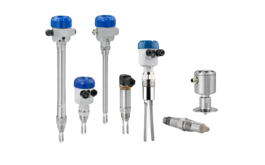
Thiết bị đo mức
Phân loại thiết bị đo mức
Hiện nay, có rất nhiều loại thiết bị đo mức sử dụng trong các ứng dụng và điều kiện khác nhau. Tùy thuộc vào các yêu cầu cụ thể của hệ thống và môi trường làm việc khác nhau, để chúng ta có thể lựa chọn các thiết bị đo mức như sau:
Loại báo mức dạng điểm

Loại đo mức dạng liên tục

Một số lưu ý khi lựa chọn thiết bị
Xác định đối tượng cần đo
Xem xét tính ẩn mòn
Xác định vị trí lắp đặt
Chọn thang đo
Chọn tín hiệu ngõ ra
Xem xét áp suất và nhiệt độ
Công nghệ đo mức nâng cao hiệu quả như thế nào trong công nghiệp?
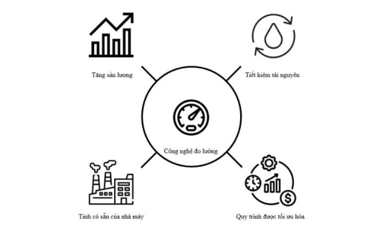
Công nghệ đo mức ngày càng phát triển và nâng cao hiệu quả trong công nghiệp với các ưu điểm như sau:
Tăng sản lượng: Cải thiện thông lượng cao hơn hoặc rút ngắn thời gian sản xuất của các quy trình ngắn hơn.
Tiết kiệm tài nguyên: Công nghệ đo lường năng cao giúp tiêu thụ ít năng lượng và các nguồn tài nguyên khác bằng cách cung cấp thông tin chính xác, tăng cường tính linh hoạt và tích hợp kiểm soát thông minh
Tính có sẵn của nhà máy: Công nghệ đo lường tiên tiến giúp giảm thời gian ngừng hoạt động không cần thiết của thiết bị bằng cách cung cấp thông tin chính xác và liên tục về trạng thái hoạt động của thiết bị. Điều này cho phép các nhà sản xuất dự đoán và phản ứng nhanh chóng đối với các vấn đề tiềm ẩn hoặc sự cố, từ đó giảm thiểu thời gian dừng máy không cần thiết để thực hiện bảo trì và sửa chữa.
Quy trình được tối ưu hóa: Công nghệ đo lường tiên tiến có thể giúp kiểm soát quy trình trong điều kiện khắc nghiệt và linh hoạt hơn trong thiết kế quy trình bằng cách tích hợp các tính năng như chịu được điều kiện khắc nghiệt, chống nhiễu, tự động hóa, IoT và AI, cùng với thiết kế quy trình linh hoạt.
Những thiết bị đo mức nổi tiếng
KROHNE hiện là một trong những nhà sản xuất hàng đầu thế giới về các giải pháp cảm biến và dòng sản phẩm đo lường chất lỏng, khí và chất rắn. Chuyên cung cấp các thiết bị đo mức sử dụng các công nghệ hiện đại như công nghệ Radar, ultrasonic và hydrostatic để đo mức các chất lỏng và chất rắn trong các bồn, thùng chứa và hệ thống.
Thiết bị đo mức dạng Radar (FMCW) (Radar (FMCW) level transmitters): Thiết bị đo mức dạng Radar không tiếp xúc của chất lỏng, bột nhão, hạt, bột và các chất rắn khác.
Thiết bị đo mức dạng Guided Radar (Guided radar (TDR) level transmitters): Thiết bị còn được gọi là phản xạ miền thời gian (Time Domain reflectometry – TDR) hoặc radar xung vi mô (micro-impulse radar -MIR). Thiết bị dùng để đo mức tiếp xúc chất lỏng, chất rắn hoặc bề mặt hai môi trường chất lỏng khác nhau trong bể chứa.
Thiết bị đo mức dạng siêu âm (Ultrasonic level transmitters): Thiết bị đo mức không tiếp xúc của các chất lỏng hoặc chất rắn.
Thiết bị đo mức (Displacer level transmitters): Đo mức dạng tiếp xúc của chất lỏng và bề mặt hai môi trường chất lỏng khác nhau trong bể chứa
Qua bài viết này, chúng ta có thể biết thêm về thiết bị đo mức đóng vai trò quan trọng trong việc quản lý chất lỏng, chất rắn và khí trong các quy trình công nghiệp và ứng dụng khác nhau. Công ty TNHH TESFA rất vinh dự là một trong những đại lý phân phối ủy quyền hàng đầu của hãng KROHNE hân hạnh đồng hành cùng quý khách!
Liên hệ hotline: +84 905 997 598 or email: [email protected]
#Thiêt bị đo mức#Tesfa#Krohne#Thiết bị tự động hoá#Ứng dụng của tesfa#Công nghệ đo mức nâng cao hiệu quả
2 notes
·
View notes
Text
In-Depth Understanding of Fiber Optic Sensing Network
Fiber optic sensing network is a tendency for many applications. It supports a large number of sensors in a single optical fiber with high-speed, high security, and low attenuation. This article provides some information about fiber optic sensing networks.
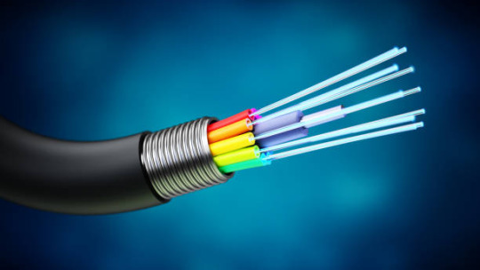
What is Fiber Optic Sensing Network?
A fiber optic sensing network detects changes in temperature, strain, vibrations, and sound by using the physical properties of light as it travels along an optical fiber. The optical fiber itself is the sensor, resulting in thousands of continuous sensor points along the fiber length.
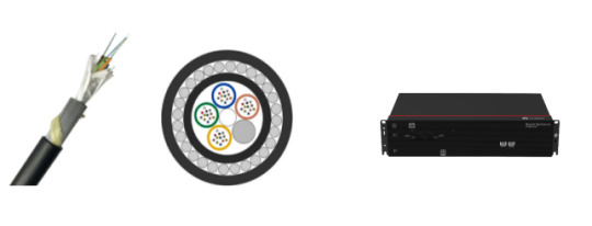
How Does Fiber Optic Sensing Network work?
A fiber optic sensing network works by measuring changes in the backscattered light inside of the fiber when it meets temperature, strain, and vibration.
Rayleigh scattering is produced by fluctuations in the density inside of the fiber. Raman scattering is produced by the interaction with molecular vibration inside the fiber. The intensity of anti-Stokes rays is mainly dependent on temperature. Brillouin scattering is caused by the interaction with sound waves inside the medium. The frequency is dependent on strain and temperature.
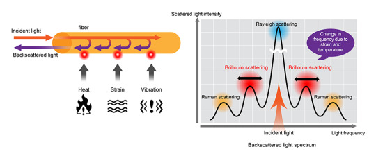
Operating Principle of Fiber Optic Sensing Network
Optical Time Domain Reflectometry (OTDR)
In the OTDR principle, a laser pulse is generated from solid-state or semiconductor lasers and is sent into the fiber. The backscattered light is analyzed for temperature monitoring. From the time it takes the backscattered light to return to the detection unit, it is possible to locate the location of the temperature event.
Optical Frequency Domain Reflectometry (OFDR)
The OFDR principle provides information about the local characteristics of temperature. This information is only available when the signal is backscattered in the function of frequency. It allows for efficient use of available bandwidth and enables distributed sensing with a maximum updated rate in the fiber.
Fiber Optic Sensing Network Technologies
Distributed Temperature Sensing (DTS): DTS uses the Raman effect to measure temperature distribution over the length of a fiber optic cable using the fiber itself as the sensing element.
Distributed Acoustic Sensing (DAS): DAS uses Rayleigh scattering in the optical fiber to detect acoustic vibration.
Distributed Strain Sensing (DSS): DSS provides spatially resolved elongation (strain) shapes along an optical fiber by combining multiple sensing cables at different positions in the asset cross-section.
Distributed Strain and Temperature Sensing (DSTS): DSTS uses Brillouin scattering in optical fibers to measure changes in temperature and strain along the length of an optical fiber.
Electricity DTS: Reliable temperature measurement of high-voltage transmission lines is essential to help meet the rising electricity demand. Fiber optic sensing, integrated into distributed temperature sensors on power lines, help ensure optimal safety and performance in both medium- and long-distance systems.
Oil and Gas DTS : Many lands and subsea oil operations rely heavily on DTS for improved safety and functionality in harsh environments. Fiber optic sensing ensures reliable performance and durability in high-temperature, high-pressure, and hydrogen-rich environments.
Oil and Gas DAS: The optical fiber in DAS creates a long sensor element that can detect high-resolution events throughout the entire length of the fiber.
Fiber Optic Navigation Sensing: Fiber optics are used in navigation systems to provide accurate information about location and direction. Aircraft, missiles, unmanned aerial vehicles (UAVs), and ground vehicles require advanced optical fiber navigation technology to ensure reliability and safety.
Fiber Optic Shape Sensing Technology: Reconstructs and displays the entire shape of optical fiber in 2D and 3D. The technology enables cutting-edge applications such as robotic, minimally invasive surgery, energy, virtual Reality (VR), etc.
Wavelength Division Multiplexing (WDM) Technology: Use of Fiber Bragg Gratings (FBGs) with different reflection wavelengths (Bragg wavelengths) in one optical fiber.
Applications
A fiber optic sensing network is used to monitor pipelines, bridges, tunnels, roadways, and railways. Also, it is used in oil & gas, power and utility, safety and security, fire detection, industrial, civil engineering, transportation, military, smart city, minimally invasive surgery, internet of thing (IoT), etc.

Conclusion
A fiber optic sensing network has high bandwidth, security, and stability, is immune to electromagnetic interference, and is lightweight, small in size, and easy to deploy. Sun Telecom specializes in providing one-stop total fiber optic solutions for all fiber optic application industries worldwide. Contact us if any needs.
2 notes
·
View notes
Text
I'll admit to being something of a RF cultist. Something something microwave-frequency circuit design. It was a while ago, but the fundamentals haven't changed. I'm going to back up the electrical engineer with some physics background because holy shit this magic is even blacker than they're letting on.
The dark gods of time and frequency domain reflectometry are somewhat lax in the enforcement of their laws at the lower ends of their realms (and it is within this laxity which our technology mostly functions), but as you put more energy into a signal (and therefore at higher frequencies), they become very harsh and strict in their demands. They require more exacting sigils and more intricate incantations. Because yes, beyond a certain point "Everything becomes an antenna." This story we tell ourselves is that this is due to quantum mechanics, which is not normally taught to engineers (See: "forbidden magics that can drive the most steady man to the horrible comforts of oblivion found at the bottom of a bottle"). Indeed even quantum physicists use shorthand notation, rather than the actual incantations of the "mathematical physicists" because the shorthand is easier on the mind. Typically the mathematicians don't allow the physicists entry into their dark domain, but the mathematical physicists are dedicated to providing "mathematical rigor" to the foundations of physics, and mathematicians respect that. In their training, quantum physicists are told that all the equations governing these things are strictly linear (because non-linearity introduces infinities one should not contemplate), and any complex values (involving imaginary numbers) must cancel out of the results (so that all observed values are real values). But the truth is the dark gods do not care if things spiral off into infinity or distances contain imaginary components. Those are just things we ignore on our end of the deal in order to remain sane.
And flat out, there is a disconnect between quantum mechanics (how small things operate at extremes) and relativity (how large things operate at extremes). We have two models when we should have one, and the small model does not contain time. Mathematically it relies upon Hilbert spaces (See: "forbidden magics that can drive the most steady man to the horrible comforts of oblivion found at the bottom of a bottle"), which is inconsistent with the time-domain. So when we petition the dark gods, they respond that we've not formatted our petition correctly, and although they do not punish us for our hubris, they deny our petitions. Our understanding perishes, but engineers aren't provided the tools to draft petitions to the deities at this level. I can't tell you why only the Kakashi bookmark worked to restore the circuit to its normal function. It is buried within the intricacies of stray capacitance ("Everything is an antenna." Therefore everything contains a resonant circuit).
Anything more involved than this quickly spirals off into spectral theory, rigged Hilbert spaces, and other functional analysis mere mortal minds like my own aren't meant to contemplate. There are things within physics which are still not rigorously defined mathematically, and it's best not to think too deeply upon the forbidden magics.
they used to make smackable technology. you used to be able to hit your tv when it didn't work good.
160K notes
·
View notes
Text
0 notes
Text
0 notes
Text
Our expert cable fault location services utilize advanced technology to pinpoint issues quickly and efficiently
Reliability is the key to today's world, whether in a home, business, or industrial sector. Over time, cables degrade, environmental damage occurs, or accidental damage results in cable faults. If this isn't resolved, downtime increases exponentially, and repair bills multiply by thousands. This is when our experts come into play in fault-locating cables using advanced technology and detecting the problem quickly.
Cable Fault Location End
Cable fault location is an important service that will identify the exact location of issues within electrical cables. These interruptions can arise from physical damage, insulation failures, or environmental influences. The ability to locate these faults precisely minimizes the extensive digging and disruption associated with traditional methods, allowing for targeted repairs.
At the heart of our services is advanced technology which improves our ability to fault detect. We use some of the following techniques of Time Domain Reflectometry, acoustic monitoring, and a host of specialized equipment to get faults quickly localized. Accuracy not only cuts down the time to be taken on repairs but also saves customers a lot of money through labor and material costs.
Advanced Technology at Work
The backbone of our cable fault location services is the application of sophisticated electrical test equipment. These include the fault locators and ground fault detectors, which are basically designed to analyze and interpret reflected signals from the faults in the cable. Our technicians are trained to make efficient use of this technology to enable diagnosis with unprecedented accuracy.
Our approach, however also encompasses earth testing services that comprehensively test the integrity and the viability of grounding systems. This area is very significant in making sure that any electrical installations are safe enough and operational. Well grounded systems make it less probable to receive electrical shock and breakdown of the equipment that would worsen the problems with cables.
Electrical Factory Acceptance Testing Is Important
Before the cables are installed, it is important to check their quality and reliability. This is where our electrical factory acceptance testing comes in. EFAT is a preventive measure that helps in identifying potential faults at the manufacturing stage. By conducting thorough tests on electrical equipment before it leaves the factory, we can ensure that only the highest quality products are deployed in the field.
This proactive approach further reduces the chances of cable faults happening in the first place. By solving potential problems before installation, we create a safer environment for users and reduce the overall cost incurred by businesses due to repairs and replacements.
Rapid Response and Efficient Solutions
Our team at PESVS knows that time is of the essence in cable faults. Delays can translate to operational downtimes, which can impact productivity and profitability severely. That's why we pride ourselves on being responsive. Our technicians are equipped with the latest tools and technology to provide rapid fault location services, often resolving issues on-site in record times.
For cable fault location projects, we adopt a systematic process. Our technicians conduct an initial assessment followed by employing advanced fault location techniques to identify the cause of the problem. Then we present a comprehensive report indicating the problem and its suggested solutions. This makes our clients informed at each and every step of the project.
Conclusion
This world of electrical infrastructure no longer requires such cable faults to occur which may lead to more interruptions, or high cost of rectifying the fault. Modern Cable Fault Location through technologically advanced methods such as earth testing, and strict acceptance of testing before placing in the field; therefore, issues identified will promptly solve and rectify that cause.
Our electrical test equipment and customer satisfaction make us stand in the industry. We may be dealing with persistent electrical problems or just looking for preventive measures for your installations. Whether it is, our efficient cable fault location services are there for you. Protect your investment and rely on the reliability of the electrical systems with our advanced solution. Reach out today and learn more about how we can help you!
#electrical earthing system#electrical test equipment#electrical testing services#cable fault location#earth testing#lightning protection system
0 notes
Text
0 notes
Text
0 notes
Text
The Role of Electric Optical Fiber Delay Lines in Modern Technology
Electric Optical Fiber Delay Lines (EOF-DLs) are indispensable components in modern telecommunication and scientific research applications. These devices allow precise control of the time delay in light transmission, enabling technologies to function with high accuracy in fields like radar systems, optical coherence tomography (OCT), and fiber optic sensors.
Understanding Electric Optical Fiber Delay Lines
Electric Optical Fiber Delay Lines are specialized tools designed to adjust the timing of light pulses as they travel through fiber optics. By introducing a controlled delay, these systems can synchronize or desynchronize signals in a way that is highly beneficial in real-time communication or data processing systems. The core feature of EOF-DLs lies in their high delay precision, which can span from picoseconds to femtoseconds. This accuracy is crucial when minute timing differences can significantly impact system performance.
The structure of EOF-DLs is simple but robust. With high reliability, low insertion loss (as low as <0.1dB in polarization-related loss), and customization options for a wide range of applications, these devices are versatile. They are engineered to function across various wavelength ranges such as the C-band and L-band, commonly used in telecommunications.

Applications Across Industries
EOF-DLs are utilized across a variety of industries due to their ability to delay optical signals with incredible precision. In radar testing and calibration, for instance, these devices provide the necessary signal delay to simulate different distances and scenarios, allowing for better performance analysis. Similarly, in medical imaging, particularly optical coherence tomography (OCT), EOF-DLs help produce high-resolution cross-sectional images by fine-tuning the timing of reflected light.
In scientific research, fiber optic delay lines play a pivotal role in light interferometry, Fourier spectroscopic analysis, and optical coherence domain reflectometry (OCDR). These systems can measure minute changes in physical phenomena by precisely timing the interaction of light with matter, providing unparalleled detail in research data.
The Future of Optical Fiber Delay Lines
As the demand for faster and more accurate data processing grows, the role of EOF-DLs is only expected to expand. Innovations in optical networks, radar systems, and advanced imaging will require even more precise timing control, and delay lines will be essential in meeting these needs. In the future, we can anticipate the development of even smaller, more efficient EOF-DLs capable of handling larger bandwidths with minimal power consumption.
In conclusion, Electric Optical Fiber Delay Lines are critical to various fields of modern technology, enabling precision in everything from telecommunications to medical imaging. As we move towards a future driven by high-speed, data-rich applications, these devices will continue to play a foundational role.
0 notes
Text
Which reflectometer to choose for new fiber-optic lines?
Modernization of 100/400G networks and deployment of 5G networks at the proper quality level require testing of optical fiber communication lines (OFC). Choosing the right methods and additional instruments is critical when conducting bulk testing, as mistakes can be very costly.
If we talk any modern optical networks, fiber and coupling quality are critical. Modernization of existing networks involves checking their condition as well as laying new OFCs—testing the quality of connections. The higher the speed of fiber-optic lines, the more stringent the requirements for the quality of their diagnostics. And here the problem of choosing a testing methodology arises: for example, is "testing to the maximum" using bidirectional tests always the best option?
Bidirectional testing of OFCs with a reflectometer: the answer or new problems?
It is important to understand that fiber-optic communication is related to reflectometry. Without a high-quality optical reflectometer (OTDR), it is impossible to create a reliably operating fiber-optic link. The solution to the problem of testing comes down to the correct initial selection of equipment and determining the most suitable methodology.
There are two main methods of reflectometry: one-way (one compensation coil at one end of the line; launch cable box) or two-way (Bi-dir OTDR, with a compensation coil at the near end and the same at the far end). .
The direction of the emitted light can influence the test results. In any fiber, there is a difference in the return loss coefficients, and in one particular direction, the light loss may be greater.
Single-sided OTDR testing can miss many anomalies. Wire junctions with different return loss values can compensate for the signal loss in one orientation and attenuate it in the other. In addition, there are dead zones in which the OTDR does not record events.
The figure below shows an example of the difference in signal loss depending on the measurement direction. One side of the testing even shows a negative loss of -0.3 dB, which is, of course, impossible. In this case, an amplification effect is observed due to the difference in the backscatter coefficient (BSC) at the junction of the two cables.

Therefore, one-way OTDR testing is better suited for simple tests such as finding and locating fiber breaks and bends, assessing total signal attenuation in fibers, testing connectors, etc. In this case, there is no need to waste time on bidirectional testing. The main advantage of unidirectional fiber-optic testing is that it is enough to inspect and clean the fiber just once for any one line. This is important since contamination of the connectors can lead to failure of the fiber-optic line, which was working properly before testing. Sometimes customers insist on two-way "full testing," but this can be excessive and even harmful as it introduces an unnecessary risk of damage while cleaning the optical connectors.
Bidirectional fiber inspection without running around
One-sided tests are not accurate when laying new lines and monitoring the performance of FOCs. In such cases, industry standards require bidirectional testing with an optical time domain reflectometer (Bi-dir OTDR) measuring the signal at both ends of the line. This is necessary to identify anomalies that are not detected by conventional one-way reflectometry. In addition, there are unique cases where a line uses cables with different fiber diameters, where bidirectional effects can be important. Bi-dir OTDR testing makes it possible to average the measurement parameters and give a clear assessment of the quality of the fiber-optic link. Ultimately, it is possible to unambiguously determine whether the tested line supports high-speed data transfer. This saves time and money that the customer may lose if the cable system fails on launch.
Traditional bidirectional testing of fiber-optic links implies first measuring one side:

And then testing the optical line on the other side:

Then obtain the average parameters. This is an important job that requires manual data processing. It can be accelerated by using two similar instruments with two external cable routes simultaneously (the bidirectional reflectometer technique), but this requires additional equipment expenses.

Another effective technique is testing with an optical reflectometer with a closed circuit (loopback). This method involves using a reflectometer at one end of the line and a reference fiber loop at the other. This way, one can test two optical lines in both directions, alternately swapping cables. This is the most effective method in terms of cost and labor savings since it requires only one reflectometer, loop switching, and two compensation coils.

A major drawback of OTDR-loopback testing is the labor-intensive process of recording and merging test data. Often, manual work with data leads to errors, and repeated tests are needed. This problem has been solved in modern optical reflectometers, such as the VIAVI T-BERD/MTS-4000 V2.
When using such advanced devices, the task of specialists is reduced to the high-quality implementation of procedures for cleaning contamination of optical connectors and one-way checking of launch cables before starting bi-directional testing.
Thus, preference should be given to OTDR modules and platforms that offer the ability to choose any optical cable diagnostic technique with maximum automation. This choice should be made based on practical needs and not on the capabilities of existing equipment. Ultimately, this approach reduces the likelihood of OFC failures.
0 notes
Text
ISRO successfully launched the EOS-08 Satellite : Overview
ISRO successfully launched the EOS-08 Earth Observation Satellite using the Small Satellite Launch Vehicle (SSLV)-D3 from the Satish Dhawan Space Centre in Sriharikota on Friday, August 16 at 9:17 am IST.This marks the third and final test flight of the SSLV, officially completing its development phase.

EOS-08 mission objectives
The primary objectives of the EOS-08 mission include designing and developing a microsatellite, creating payload instruments compatible with the microsatellite bus, and incorporating new technologies required for future operational satellite.
General Specifications
- Weight: Approximately 175.5 kg
- Power Generation: About 420 W
- Mission Life: 1 year
- Orbit: Circular Low Earth Orbit (LEO) at an altitude of 475 km and an inclination of 37.4°
Payloads
- Electro-Optical Infrared Payload (EOIR): Designed for satellite-based surveillance, environmental monitoring, and disaster management, it operates in the mid-wave infrared (MIR) and long-wave infrared (LWIR) bands.
- Global Navigation Satellite System-Reflectometry Payload (GNSS-R): Used for ocean surface wind analysis.
- SiC UV Dosimeter: Monitors UV radiation.
It is designed for wide range of applications such as Disaster monitering, environmental monitoring, Infrastructure monitoring, fire detection,forest cover mapping, water quality monitoring, weather forecasting, Border monitoring, Volcanic Activity observations. By providing critical data and insights, EOS-08 contributes to informed decision-making, sustainable development, and environmental stewardship.
About Small Satellite Launch Vehicle (SSLV) -D3
-SSLV-D3 is the third developmental flight of SSLV.
-SSLV is capable of launching Mini, Micro or Nano satellites (10 to 500 kg mass) into 500km planar orbit.
-It uses three solid fuel-based stages and a final liquid-fuel based stage.
-Benefits: Low cost, low turn-around time, flexibility in accommodating multiple satellites, launch on demand feasibility, minimal launch infrastructure requirements, etc.
The EOS-08 mission marks a significant milestone in India's space program, showcasing the country's growing capabilities in developing advanced satellite technology and achieving complex scientific objectives.EOS-08 highlights India's self-reliance and innovation in space exploration, with ISRO developing indigenous technologies and innovative solutions to overcome technical challenges. The success of EOS-08 solidifies India's position as a significant player in the global space community.
The EOS-08 mission sends a strong message about India's capabilities, commitments, and aspirations in space exploration and its applications for the betterment of humanity.
Jai Hind 🇮🇳🇮🇳🇮🇳
0 notes
Text
SSLV T-3 rocket successfully launched with EOS-08 satellite
SSLV T-3 rocket successfully launched with EOS-08 satellite. The Indian Space Research Organization (ISRO) has designed a state-of-the-art 175.5 kg satellite called EOS-08 for Earth observation operations. The EOS-08 satellite carries an Electro-Optical Infrared payload (EOIR), Global Navigation Satellite System-Reflectometry payload (JNSS-R) and SIC. UV dosimeters are attached. The tenure of…
0 notes