#Leadscrewlinearactuators
Explore tagged Tumblr posts
Text
Modular Electric Slides

Modular Electric Slides You are welcome to visit our download centre to check E-catalogues or watch our video centre to check more projects. Modular Electric Slides, also can be named as High Precision Linear Modules, Linear Motion Module, Industrial Linear Motion, Linear Actuator Bundle, etc in this industrial automation. Tallman Robotics’s Modular Electric Slides type TM220 with body with by 220mm have 4 series. These Linear slides have 0 mm to 3500 mm stroke, and 8kgs up to 150kgs input payload. TM Modular Electric Slides can be integrated with many brand motors by 50W,100W,200W/400W /750W/1000W or 42, 57,86 stepper motors or NMEA17, NMEA23, NMEA34 stepping motors in extruded super quality AL frame system to ensure requirement of precision and common projects. Precision, Stroke, lead, Brake and no Brake can be selected depending on your specific details. TM by Tallman Robotics, which is located in Shenzhen, has strong ability in design and engineering experience. We have exported all kinds of Modular Electric Slides such as screw driven modules, belt driven modules, and also ,also there are semi sealed type and fully sealed type for common and dust free applications. Our Modular Electric Slides perform all kinds of application such as: Winding Machine by eliminating the clearance of the traverse axis Circuit Board Mounting with linear modules used in high-precision and compact circuit board mounted. Driller with high rigidity linear module used in the drilling machine Positioning Device with linear module used for the moving parts of the work piece and the welding moving parts. Dispenser with linear module used in the dispenser, the movement is smooth and the coating is even., Laser Marking with linear module used in the laser marking machine in a clean room, etc.
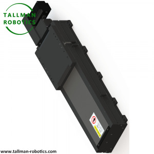
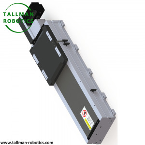
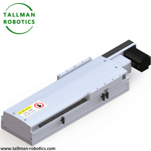
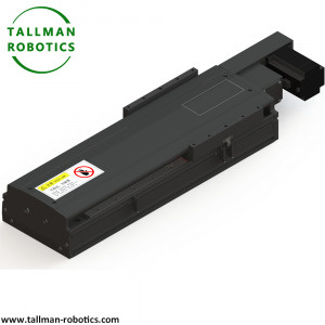
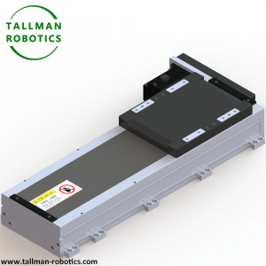
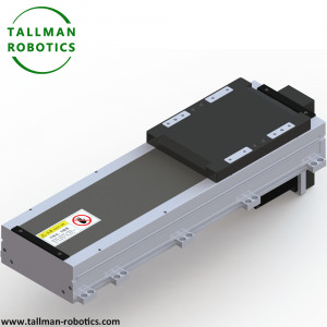
Basic Specification of TM220 Modular Electric Slides series Model No TMS220-CM TMS220CR Drive solution Ball screw Sealed or not Semi closed Fully closed Motor power AC (W) 400W/750 Repeatability (mm) ±0.01/±0.005 Ball screw outer diameter (mm) 25 lead (mm) 5 10 25 50 Fastest speed Motor speed 3000 (rpm) 250 500 1250 2500 Max Load(kg) Acceleration Deceleration Horizontal 0.3G 150 150 120 50 Vertical 0.3G 55 45 20 8 Rate Thrust (N) 2100 1050 420 210 Linear guide (mm) 23*18.5-2 Origin sensor: Plug-in EE-SX672(NPN)EE-SX672P(PNP) Inside EE-SX951(NPN)EE-SX951P(PNP) Model No TMB220-CM TMB220-CR Drive solution Timing Belt Timing Belt Sealed or not Semi closed Fully closed Motor power AC (W) 750w Repeatability (mm) ±0.04 Reduction Ratio 1:1 1:2 lead (mm) 90 45 Fastest speed Motor speed 3000 (rpm) 4500 2250 Max Load(kg) Acceleration Deceleration Horizontal 0.3G 35 75 Vertical 0.3G - Rate Thrust (N) 163 326 Linear guide (mm) 23*18.5-2 Origin sensor: Plug-in EE-SX672(NPN)EE-SX672P(PNP) Inside EE-SX951(NPN)EE-SX951P(PNP) Related knowledge: Common problems and countermeasures for installation and use of single-axis and multi-axis robotic arms a. The flatness of the bottom surface of the single-axis manipulator installation does not meet the standard. If the flatness of the bottom surface of the single-axis manipulator is too large, the bottom surface of the electric slide table will be forcibly locked, resulting in strong bending deformation of the bottom surface of the slide table, linear guide rails and ball screws. If it is light, it will increase the running resistance of the single-axis manipulator. If it is heavy, the electric slide may not be able to run, and the life of the electric slide will be shortened sharply. According to the accuracy level of the single-axis manipulator, the flatness of the general installation level should be less than 0.05mm/m. For the precision grade, the flatness of the bottom surface of the installation should be less than 0.02mm/mm. b. The locking order of the fixing screws at the bottom of the single-axis manipulator is wrong. The fixing screw at the bottom of the single-axis manipulator should follow the principle of first middle, then both ends, and then locked in sequence. If the two ends are locked first, the arch deformation caused by the deformation cannot be eliminated, resulting in the linear guide rail not running smoothly, reducing the walking parallelism and straightness accuracy. c. The motor shaft of the single-axis manipulator and the end of the screw shaft are not concentric. Although the coupling can eliminate a certain degree of eccentricity, if the value of the concentricity runout of the shaft end of the single-axis manipulator screw and the motor shaft exceeds the allowable range of the coupling, the damage of the coupling will be accelerated, causing the coupling to be different. Sound, or shrapnel breaks. It should be avoided as much as possible. d. The installation height of both sides of the multi-axis gantry combined mechanical arm is uneven. When the mechanical arm is installed in a gantry type, if the height of the guide rails on both sides is uneven, or the two slides are not parallel, the electric slide will be held back and the damage of the electric slide will be accelerated. f. The single-shaft electric slide timing belt tension is too loose or too tight. The tension of the timing belt of the electric sliding table should be kept moderate. If the belt tension is too tight, the tension of the timing wheel and the timing belt will be too large, and there will be abnormal noise. If the belt tension is too loose, it will cause gaps in the transmission process and reduce accuracy. In severe cases, it will produce tooth skipping. The tension of the synchronous belt is generally determined by the tension and deflection. The measurement method is: use a thrust meter to press the vertical direction of the belt midpoint and apply a certain amount of installation force to measure the resulting deflection value. Reference values corresponding to different center distances and belt specifications. g. The installation of the timing belt of the single-axis electric slide is not aligned. The synchronous belt-driven electric slide table, or the motor-mounted electric slide table on the side of the motor, should keep the synchronous wheel flush, otherwise, it will cause the belt to deviate, and then the belt edge and the synchronous belt rib friction will occur, the synchronous belt within a short time Will be damaged and broken. h. The single axis electric slide induction switch collides with the sensor due to deformation. The induction slide of the electric slide induction switch is damaged due to deformation and collision with the photoelectric switch. Countermeasure: Before energizing and sliding the slider, first check the photoelectric switch. You can pass the photoelectric switch normally. i. The stroke of the cantilever shaft of the mechanical arm (electric slide) is too long, and the overhang length is too large. If the cantilever length of the robot arm is too large, the allowable torque of the guide rail will be overloaded. Under different accelerations and decelerations, the closing time will change. The vibration generated at the end of the beam is finally absorbed by the electric slide table. Long-term vibration will shorten the life of the guide rail. j. The load of the robot arm/electric slide exceeds the range of use. When selecting the robotic arm, in addition to referring to the loadable load data in the selection manual, the effects of the dynamic allowable torque, acceleration and deceleration changes, and cantilever length should also be checked, and sufficient safety factors should be reserved. k. The wiring of the robot arm sensor switch is wrong or burned due to overvoltage. The electric slide induction switch generally uses a photoelectric switch. The reverse connection of the positive and negative poles of the photoelectric switch will cause damage to the photoelectric switch. The photoelectric switch cannot share the power supply with the motor driver or other inductive loads. Otherwise, the back electromotive force generated by the motor or the inductive load will cause a large voltage fluctuation, which will burn the photoelectric switch. Read the full article
#BeltdriveLinearMotionGuideActuators#BeltDrivenLinearModules#Gearballscrewdrivenactuators#Leadscrewlinearactuators#Leadscrewlinearmodules#LinearGuideWays#LinearMotionSystems#LinearStages#ModularElectricSlides#ModularStages#Motionbeltdrivelinearactuators#Precisionlinearactuators#StainlessBearingActuators
0 notes