#I did not get my A6 just to see this kind of bullshit enter the industry
Explore tagged Tumblr posts
Text
okay okay okay. I'm gonna try to represent this as best I can, but I don't have access to my EWDs so I'm gonna have to do it from memory
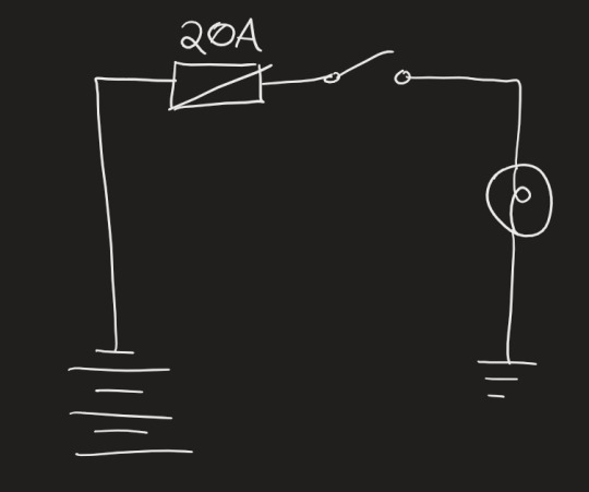
this is an example of a very simple circuit. it has:
A power source (the horizontal lines on the left represent a battery)
A protection device (the 20 amp fuse, represented by a box with a diagonal line)
A control device (the switch, currently open, represented by a line between two dots)
A load (the thing doing the actual work, in this case a light bulb represented by a circle with a swirl)
And a ground path (represented by the horizontal lines on the right. The ground returns to the negative side of the battery but for the purposes of compactness wiring diagrams are usually drawn with them terminating at the bottom)
If you want to power multiple loads from the same power source, you can run the circuit in either series or parallel. In a series circuit, loads are placed one after another on the same wire. This reduces wire length, but the loads have to share the same voltage, and so the output of each is reduced. We're gonna focus on parallel for right now because that's what most wiring harnesses are
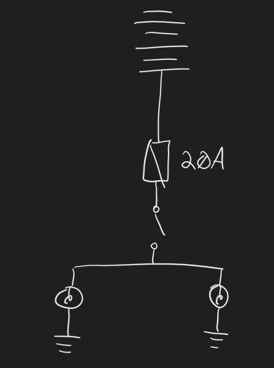
This is a parallel circuit. The wires from the battery go to two separate bulbs. The benefit of a parallel circuit is that both bulbs will get the same amount of power (it has to do with voltages and amperage and some annoying math so it doesn't violate conservation of energy). These are good because it means a break in one of the sub-circuits won't affect the operation of the other bulb. But a break in the master circuit will take out both bulbs
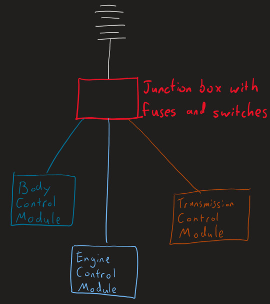
This is a basic overview of how wiring harnesses work in a vehicle. You can see that all the modules are wired in parallel, so if one goes down it doesn't take out the rest of them

If we zoom in on, say, the BCM, we can see that it controls a number of different actuators, motors, and sensors

If we zoom in further, we can see that the seatbelt ECU (Electronics Control Unit) is connected to the actual sensor itself with 3 wires: Power (red), Signal (green), and Ground (white). Many circuits are much more complicated than this (for example, the starter circuit), but this is the basic layout of the circuit heirarchy found in every harness in your vehicle.

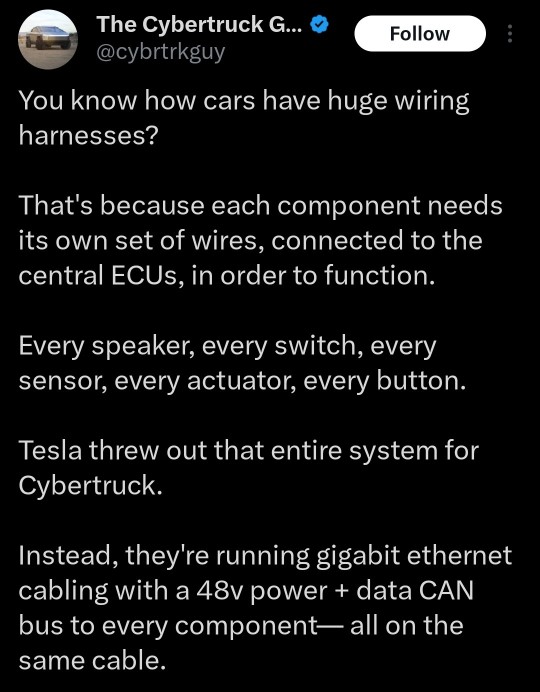
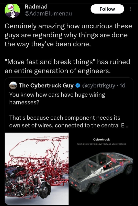
This is what the geniuses at Tesla are trying to do. As you can see, a break anywhere on this big loop will knock out power to every single system on it, because they'll all simultaneously lose their ground. The reason they need 48 volts instead of the typical 12 is because running everything in series means each bulb, motor, sensor, whatever, is going to run at reduced power. it's a disaster of electrical wiring and is the sign of someone who wants to be different for the sake of being different. There's a reason we structure vehicle electronics the way we do



41K notes
·
View notes