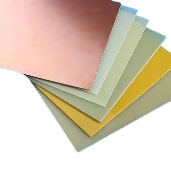
#FR4 Epoxy Fiberglass Board
Explore tagged Tumblr posts
Visit Tumblr Blog
Explore Tumblr blogs with no restrictions, modern design and the best experience.
Last Seen Tumblr Blogs


Fun Fact
Average visit duration of Tumblr.com is 10 mins and 25 secs.
Text
G10 & FR4 Sheet: Cutting Edge Technology in Materials Science
In today’s rapidly developing science and technology field, materials science is gradually becoming a key factor in promoting social progress and industrial upgrading. As an important part of materials science, G10 and FR4 sheet play a key role in many engineering applications, demonstrating the charm of cutting-edge technology. This article will delve into the cutting-edge technologies of G10…

View On WordPress
0 notes
Text
HDPE Plastic and FR4 Composite: Essential Materials for Modern Industry
GRM Custom Products is dedicated to delivering innovative, high-quality materials that meet the evolving needs of various industries. Among our product offerings, HDPE plastic and FR4 composite stand out as essential materials used across many applications. In this blog, we explore the unique properties, benefits, and common uses of these two versatile materials, helping you better understand why they are indispensable in modern manufacturing and design.
Understanding HDPE Plastic
High-Density Polyethylene (HDPE) is a widely-used thermoplastic known for its durability, strength, and resistance to impact and moisture. Here’s why HDPE is a material of choice in many sectors:

Key Properties of HDPE Plastic
High Strength-to-Weight Ratio: HDPE is lightweight yet extremely durable, which makes it easy to transport and ideal for applications that require high tensile strength.
Chemical and Moisture Resistance: This material is highly resistant to chemicals and water, allowing it to endure harsh environmental conditions without degrading.
Impact Resistance: HDPE can absorb impact without cracking or breaking, making it ideal for demanding applications such as protective equipment or industrial components.
Ease of Fabrication: HDPE is easy to machine and shape, providing flexibility for custom designs and complex manufacturing needs.
Common Applications of HDPE Plastic
At GRM Custom Products, we often recommend HDPE plastic for applications where durability and adaptability are paramount. Common uses include:
Industrial Containers: HDPE’s resistance to chemicals makes it ideal for manufacturing chemical containers and storage tanks.
Pipe Systems: Its durability and moisture resistance make HDPE an excellent choice for piping and water transportation systems.
Construction Components: HDPE plastic is often used in geomembranes, flooring, and other construction materials due to its high impact resistance and weather resilience.
Packaging: Lightweight yet durable, HDPE is a popular choice for packaging, especially for food and beverage containers.
Exploring FR4 Composite
FR4 composite is a versatile, flame-resistant material predominantly used in the electronics industry. Made from a fiberglass-reinforced epoxy laminate, FR4 is known for its strength, lightweight properties, and excellent electrical insulation capabilities.
Key Properties of FR4 Composite
High Dielectric Strength: FR4 offers excellent electrical insulation, making it ideal for applications requiring high voltage resistance.
Flame Resistance: The flame-retardant properties of FR4 composite help ensure safety, especially in high-temperature environments.
Mechanical Strength: FR4 is rigid, durable, and resistant to bending, allowing it to maintain structural integrity under various conditions.
Low Moisture Absorption: This material resists moisture absorption, which helps maintain its properties even in humid or wet conditions.
Common Applications of FR4 Composite
FR4 is a critical component in the electronics and electrical industries. At GRM Custom Products, we see strong demand for FR4 composite in:
Printed Circuit Boards (PCBs): FR4 is the primary material for PCBs due to its excellent insulation and mechanical properties.
Insulation Panels: The flame resistance and dielectric properties of FR4 make it a safe choice for insulation in high-voltage electrical panels.
Aerospace Components: FR4 composite is used in aerospace applications where lightweight, high-strength, and fire-resistant materials are necessary.
Test Fixtures and Jigs: The stability and resilience of FR4 make it ideal for custom manufacturing jigs, where reliable performance is essential.
HDPE Plastic vs. FR4 Composite: Which is Right for Your Application?
While both HDPE plastic and FR4 composite offer outstanding durability and resistance to environmental factors, they serve distinct purposes based on industry needs. HDPE plastic is often preferred for projects requiring chemical resistance, impact strength, and cost-effectiveness. Its versatility makes it suitable for industrial containers, piping, and construction. FR4 composite, on the other hand, is designed for high-performance applications, especially in the electronics and electrical sectors. Its flame resistance, electrical insulation, and rigidity make it the material of choice for circuit boards, insulation, and aerospace components.
Why Choose GRM Custom Products?
At GRM Custom Products, we pride ourselves on providing top-quality materials tailored to your specific industry needs. We offer custom solutions in HDPE plastic and FR4 composite, ensuring that you receive products that meet rigorous standards for safety, durability, and performance. Our team of experts works closely with clients to recommend the best material for each application, delivering solutions that help drive innovation and efficiency in your operations.
Conclusion
If you’re looking for reliable, high-performance materials like HDPE plastic or FR4 composite, GRM Custom Products is here to help. Our extensive inventory, customized solutions, and commitment to quality make us the ideal partner for all your material needs. Contact us today to discuss your project
1 note
·
View note
Text
Aluminum pcb vs fr4 pcb board
FR4 board is a code name for the grade of flame-retardant material. It represents a material specification that the resin material must be able to extinguish by itself after burning. It is not a material name, but a material grade. Therefore, there are many types of FR-4 grade materials used for pcb, but most of them are composite materials made of so-called Tera-Function epoxy resin, Filler and glass fiber.
FR-4 PCB board, according to different uses, industry insider generally call them: FR-4 Epoxy Glass Cloth, insulating board, epoxy board, epoxy resin board, brominated epoxy resin board, FR-4 , Fiberglass board, fiberglass board, FR-4 reinforcement board, FPC reinforcement board, flexible circuit board reinforcement board, FR-4 epoxy resin board, flame-retardant insulation board, FR-4 laminated board, epoxy board , FR-4 light board, FR-4 fiberglass board, epoxy glass cloth board, epoxy glass cloth laminate, circuit board drilling pad etc.
Main technical features and applications of FR-4 board: stable electrical insulation performance, good flatness, smooth surface, no pits, thickness tolerance standards, suitable for high-performance electronic insulation requirements products, such as FPC reinforcement board, PCB drilling pad, glass fiber meson, potentiometer carbon film printed glass fiber board, precision star gear (wafer grinding), precision test plate, electrical (electrical) equipment insulation support spacer, insulation backing plate, transformer insulation plate, motor insulation, grinding gear, electronic switch insulation board, etc.
The aluminum pcb board is a metal-based copper-clad laminate with good heat dissipation function. Generally, a single-sided aluminum PCB is composed of a three-layer structure, which is a circuit layer (copper foil), an insulating layer and a metal base layer. For high-end use, it is also designed as a double-sided board, and the structure is circuit layer, insulating layer, aluminum base, insulating layer, and circuit layer. Very few applications are multi-layer boards, which can be formed by bonding ordinary multi-layer boards with insulating layers and aluminum bases.
Compared with traditional FR-4 PCB, aluminum pcb circuit boards have the following advantages:
Good thermal conductivity. The metal layer of the aluminum pcb board can quickly dissipate heat, transfer the heat of the device, minimize the thermal resistance, and have good thermal conductivity.
More environmentally friendly. Aluminum-based pcb boards do not contain substances harmful to human health and the environment, and are more environmentally friendly than FR-4 circuit boards.
High durability. FR-4 pcb may be warped, bent, cracked etc during production and transportation; ceramic substrates are also more fragile. Aluminum pcb circuit boards make up for the shortcomings of FR-4 boards and ceramic substrates, have longer durability, and avoid board cracks caused by production and transportation.
Higher performance. The circuit layer of the aluminum-based PCB board is etched to form the circuit. Compared with the traditional FR-4 pcb board, under the same line width, thickness, etc., the current carried by the aluminum pcb is higher than that of the FR-4 pcb board.

0 notes
Text

Comparison between Rogers PCB and ordinary PCB
Rogers PCBs utilize specialized laminate materials produced by Rogers Corporation, specifically selected to meet the demands of high-frequency and high-performance applications. In contrast, standard PCBs typically use FR4 materials, which are suitable for more general and standardized electronic circuits. To accurately understand the differences between these two types, several key factors must be considered, including the material properties, performance, and applications of each PCB.
Material Differences
There are significant differences between Rogers printed circuit boards and standard PCBs regarding the materials used. Below are some common materials utilized in both types of PCBs:
Rogers PCB Materials
Rogers PCB materials consist of various high-performance laminates designed specifically for high-frequency applications. These materials also exhibit excellent thermal performance. Here are some of the most commonly used materials in Rogers PCB manufacturing:
· RO3000 Series: These materials are known for their low dielectric loss, outstanding thermal management, and stable electrical performance, making them suitable for microwave applications.
· RO4000 Series: This series strikes a good balance between cost and performance, featuring low dielectric constant and high thermal stability.
· RO4350B: This laminate is widely used in RF and microwave applications due to its low dielectric constant and loss tangent, making it particularly suitable for RF applications.
Standard PCB Materials
Most standard PCBs are made using FR4 materials. This common substrate type consists of woven fiberglass and epoxy resin adhesive. FR4 is recognized for its low cost and acceptable performance in standard applications. Its dielectric constant is typically higher than that of Rogers PCBs (about 4.5), which may lead to signal attenuation in high-frequency applications. While FR4 materials perform well in low to mid-frequency ranges, they struggle to maintain good signal integrity and thermal stability in more challenging environments.
Dielectric Properties
The dielectric performance of the materials used in PCBs is crucial, especially for high-frequency applications. Dielectric performance directly affects the board's ability to transmit signals with minimal loss and interference.
Rogers Printed Circuit Boards
· Dielectric Constant: Rogers PCB materials have a low and stable dielectric constant, typically ranging from 2.2 to 3.5. A lower dielectric constant indicates that the material can support faster signal transmission with less delay, which is critical for high-frequency and high-speed applications.
· Dissipation Factor: Rogers laminates have a low dissipation factor, as low as 0.002 units. This stability of the dielectric constant across varying temperatures makes them highly suitable for applications involving rapid thermal changes, such as those found in aerospace or automotive radar systems.
Standard PCBs (FR4)
· Dielectric Constant: FR4 has a higher dielectric constant, typically around 4.0 to 4.5. This can lead to potential signal delays and more severe signal attenuation, particularly in high-speed and high-frequency applications.
· Dissipation Factor: The dissipation factor of FR4 materials is higher than that of Rogers materials, generally between 0.02 and 0.035 units. This increased dissipation factor results in greater signal loss, especially in high-frequency applications.
Cost Considerations
Cost is an important factor to consider in PCB manufacturing. Distinctions can be made between Rogers PCBs and standard PCBs due to their different material compositions.
Rogers Printed Circuit Boards
Rogers PCBs are typically more expensive due to their unique material properties and higher performance. The manufacturing process for Rogers laminates is more complex than for standard FR4 materials, aimed at achieving better signal integrity and thermal performance.
· Higher Material Costs: The superior material characteristics of Rogers laminates, such as their low dielectric constant and excellent thermal conductivity, contribute to increased PCB costs.
· Specialized Manufacturing Process: The manufacturing process for Rogers PCBs is more intricate due to the need for precise control over electrical and thermal performance, significantly increasing overall costs.
Standard PCBs
FR4 PCBs are more cost-effective compared to Rogers PCBs, making them the preferred choice for general applications. The lower material costs also translate to relatively lower manufacturing costs for standard PCBs.
· Reduced Material Costs: FR4 is generally readily available and much cheaper compared to Rogers laminates. Its affordability and quick availability make FR4 PCBs the go-to choice for consumer electronics and other cost-sensitive applications.
· Simpler Manufacturing: The production of FR4 boards does not require the precision needed for Rogers boards, greatly reducing production costs.
Applications
Rogers PCB Applications
Rogers PCBs are frequently used in applications requiring high-frequency performance, excellent signal integrity, and high thermal stability. Here are some common applications for Rogers PCBs:
· RF and Microwave Circuits: Rogers PCBs are widely employed in devices that require significant RF and microwave signal usage, such as mobile base stations, radar systems, and satellite communications.
· High-Speed Digital Circuits: Rogers PCB materials consistently support high-speed data transmission while minimizing signal loss.
· Aerospace and Military Applications: Their durability and thermal stability make Rogers laminates ideal for PCB applications in aerospace and military environments, where signal integrity is crucial.
Standard PCB Applications
FR4 is one of the commonly used materials in everyday electronics, primarily due to its low cost and good performance in most standard applications. It is utilized in:
· Consumer Electronics: Everyday devices such as smartphones, computers, and household appliances primarily rely on FR4 printed circuit boards because they are simple and inexpensive to manufacture.
· Industrial Electronics: Similar to consumer electronics, industrial electronic devices also utilize standard PCBs, where high-frequency performance is not a critical requirement.
Hitech has rich experience in Rogers PCB manufacturing. We have adequate stock for common Rogers material. If you have the requirements for such PCB products, feel free to let us know. https://www.hitechpcba.com/rogers-pcb
0 notes
Text
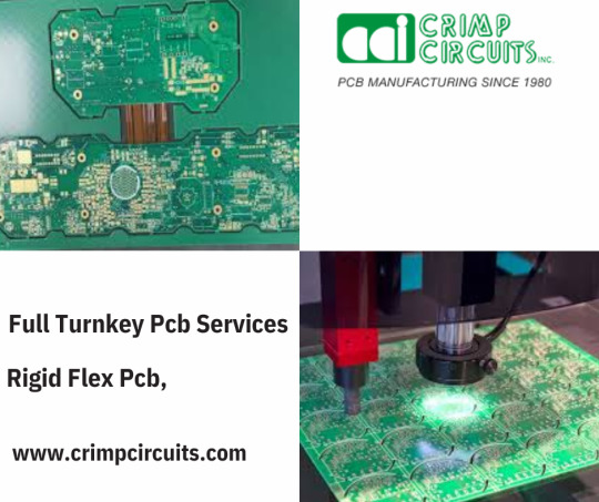
Exploring Rigid-Flex PCBs: The Future of Electronics Design
In today's rapidly advancing technological landscape, innovation in electronics is a constant force driving progress. One of the key innovations that has transformed the electronics manufacturing industry is the development of rigid-flex PCBs (Printed Circuit Boards). These specialized boards combine the durability of rigid PCBs with the flexibility of flex circuits, allowing for compact, reliable, and complex electronic designs.
In this blog, we will dive into the world of rigid-flex PCBs, exploring their structure, benefits, applications, and why they are becoming essential in modern electronic devices.
What is a Rigid-Flex PCB?
A rigid-flex PCBs is a hybrid printed circuit board that integrates both rigid and flexible circuit sections into a single design. Unlike traditional rigid PCBs that are fully solid, rigid-flex boards feature both solid and flexible areas. This combination allows manufacturers to design electronics that can conform to different shapes while maintaining the structural integrity of rigid circuits in areas where they are needed.
Rigid-flex PCBs are generally composed of multiple layers, combining rigid and flexible substrates. The rigid sections provide support and strength for components and connectors, while the flexible sections allow for movement, bending, and the capability to fold during assembly or operation. This offers a unique solution for products that need to fit into tight spaces or undergo frequent movement.
Structure of Rigid-Flex PCBs
The structure of rigid-flex PCBs consists of alternating layers of rigid and flexible materials. The rigid portions are typically made from materials like FR4 (a composite material made of woven fiberglass cloth and epoxy resin), which are sturdy and offer mechanical strength. The flexible sections, on the other hand, are made from flexible polymers like polyimide that can bend without damaging the board.
One of the major advantages of this structure is that rigid-flex PCBs eliminate the need for connectors or wiring harnesses between separate rigid and flexible components. This reduction in connectors leads to significant space savings and reduced weight, which is crucial in applications like aerospace, consumer electronics, and medical devices.
Key Benefits of Rigid-Flex PCBs
Design Flexibility One of the most significant advantages of rigid-flex PCBs is their design flexibility. Engineers can create intricate circuits that fit into compact spaces while maintaining the necessary rigidity in crucial areas. This makes them ideal for devices like smartphones, laptops, and wearables, where every millimeter of space is valuable.
Space and Weight Savings By integrating both rigid and flexible sections, rigid-flex PCBs eliminate the need for connectors and cables that would traditionally link separate PCBs. This leads to reduced weight and space savings, which is vital in industries like aerospace and defense, where every gram matters.
Improved Reliability The reduction in connectors and solder joints enhances the reliability of the final product. Connectors and cables are common points of failure in electronic devices, especially in high-vibration or high-stress environments. Rigid-flex PCBs minimize these potential failure points, ensuring longer lifespans and better performance under stress.
Enhanced Durability Rigid-flex PCBs offer enhanced durability, making them ideal for applications that require bending or movement during operation. For example, devices that feature moving parts, such as wearable technology or robotics, benefit greatly from the flexibility and durability of rigid-flex PCBs.
Cost Efficiency While the initial production costs of rigid-flex PCBs can be higher due to their complexity, the overall cost savings can be significant when considering the reduced need for connectors, cables, and assembly labor. Moreover, the reduced risk of mechanical failure translates into lower repair and replacement costs over the product’s lifecycle.
Applications of Rigid-Flex PCBs
Rigid-flex PCBs are commonly used in industries where compact design, reliability, and durability are essential. Some key application areas include:
Consumer Electronics Rigid-flex PCBs are widely used in consumer electronics such as smartphones, tablets, and wearable devices. Their ability to reduce space and improve performance in compact designs makes them ideal for today’s tech products.
Aerospace and Defense In the aerospace and defense industries, rigid-flex PCBs play a crucial role in designing lightweight, reliable, and durable systems that can withstand harsh conditions, such as high vibrations and extreme temperatures.
Medical Devices Medical devices, such as pacemakers and diagnostic equipment, often require small, lightweight, and reliable electronics. Rigid-flex PCBs allow for the creation of devices that can be implanted in the body or used in sensitive environments.
Automotive Industry With the increasing complexity of automotive systems, especially in electric vehicles (EVs), rigid-flex PCBs are used for intricate dashboard displays, sensors, and control systems. Their reliability and durability in high-temperature environments make them well-suited for automotive applications.
Conclusion
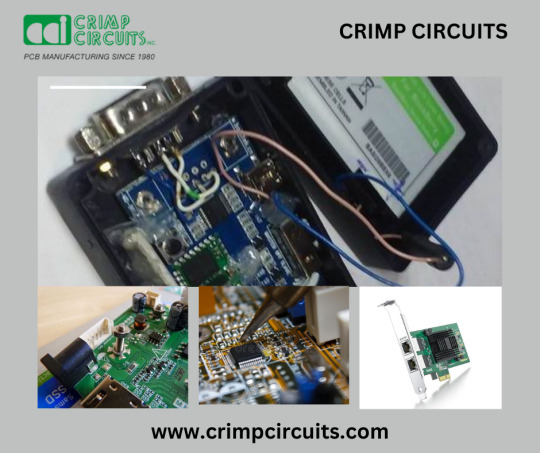
Rigid-flex PCBs represent a perfect blend of flexibility and rigidity, making them a vital component in the future of electronic design. From consumer electronics to aerospace, medical devices, and automotive systems, these hybrid PCBs are revolutionizing the way engineers approach design challenges. Their ability to combine compactness, durability, and performance positions them as a critical tool for innovators across various industries. For more details visit our website www.crimpcircuits.com
#pcb manufacturing toronto#printed circuit board design#metal clad pcb#printed circuits#rigid flex pcb#full turnkey pcb services#turnkey pcb services#pcb parts#eagle software#pcb designing#flexible pcb#pcb assembly#printed circuit board manufacturers#pcb manufacturers in canada#circuit board manufacturers in canada#pcb quote#pcb prototype services in canada
0 notes
Text
Unraveling the World of Printed Circuit Boards (PCBs)
Printed Circuit Boards (PCBs) are the backbone of modern electronics, enabling the seamless integration of electronic components into a compact and efficient system. In this blog post, we'll take a closer look at PCBs, exploring their importance, construction, types, and applications.
Understanding Printed Circuit Boards: Printed Circuit Boards
1. Importance of PCBs: Printed Circuit Boards
PCBs serve as the fundamental building blocks of electronic devices, providing a platform for connecting and mounting electronic components such as resistors, capacitors, and integrated circuits. They offer a reliable and efficient means of interconnecting components while minimizing space and maximizing functionality.
2. Construction of PCBs: Printed Circuit Boards
Substrate: The base material of a PCB, often made of fiberglass-reinforced epoxy resin (FR4), provides mechanical support and electrical insulation.
Copper Layers: Thin layers of copper foil are bonded to the substrate, forming conductive traces that carry electrical signals between components.
Solder Mask: A protective layer of solder mask is applied to the surface of the PCB, covering the copper traces and preventing oxidation.
Silkscreen: Component designators, logos, and other information are printed onto the PCB using a silkscreen layer.
3. Types of PCBs: Printed Circuit Boards
Single-Sided PCBs: Consist of a single layer of copper traces on one side of the substrate, suitable for simple electronic applications.
Double-Sided PCBs: Feature copper traces on both sides of the substrate, allowing for more complex circuitry and higher component density.
Multilayer PCBs: Utilize multiple layers of copper traces interconnected by vias, offering enhanced functionality, signal integrity, and noise immunity.
4. Applications of PCBs: Printed Circuit Boards
Consumer Electronics: PCBs are ubiquitous in consumer electronics such as smartphones, tablets, laptops, and digital cameras.
Industrial Equipment: PCBs are essential components of industrial machinery, control systems, and automation equipment.
Automotive Electronics: PCBs play a vital role in automotive applications, including engine control units (ECUs), infotainment systems, and dashboard displays.
Medical Devices: PCBs are used in medical devices such as MRI machines, patient monitors, and diagnostic equipment.
Conclusion: Printed Circuit Boards
Printed Circuit Boards are the foundation of modern electronics, enabling the seamless integration of electronic components into a wide range of devices and systems. By understanding the construction, types, and applications of PCBs, designers and engineers can leverage this essential technology to create innovative and reliable electronic products that power our interconnected world. Whether you're building a smartphone, a medical device, or an industrial control system, PCBs are the key to unlocking endless possibilities in the world of electronics
0 notes
Text
Mastering Glass Epoxy Solutions with Expert Craftsmanship
At Hason Industries, we take pride in crafting a diverse range of specialized parts, including the exceptional Glass Epoxy Slot Wedges and Spacers, tailored to meet the needs of various mechanical and electrical applications.
Applications in Electrical and Electronic Implementations
Our Glass Epoxy Components are designed to cater to a wide array of uses, from circuit board applications to insulation purposes and protective housing for electrical assemblies. These components provide essential spacer elements for insulation while offering robust structural integration for sectors such as aviation and automotive.
Performance in Challenging Conditions
Our Glass Epoxy Components are engineered to withstand elevated heat conditions, making them ideal for industrial-grade spacers for insulation purposes. With unparalleled insulative performance for Slot Wedges and resistance to moisture, they are optimized for electronic device insulation.
Mechanical Robustness and Heat Tolerance
The durability of our Glass Epoxy Components shines through their endurance under stress and flexural forces, ensuring longevity with resistance to impacts. They maintain integrity at various temperatures, making them suitable for environments exposed to heat while retaining stable dimensions despite thermal shifts.
Resistance to Chemicals and Dimensional Consistency
Our components boast the capability to endure multiple chemical interactions, making them perfect for chemically aggressive conditions. They also exhibit unwavering form amidst thermal variations and unmatched accuracy for precision components.
Epoxy Sheet Selection and Advantages
We offer an array of options including G11 category Glass Epoxy Parts, FR4 grade Glass Epoxy Slot Wedges, and variants of Epoxy Fiberglass Sheets. These selections boast advantages such as being impervious to corrosive elements, rigid without excess weight, resilient to shocks and continual wear, simplifying assembly procedures while being cost-effective in maintenance with inherent electrical insulation.
Why Choose Hason Industries?
Hason Industries stands as the benchmark for robustness and insulative integrity in Glass Epoxy Components. Our products represent precision engineering excellence that ensures steadfast performance and reliability even in critical situations.
Frequently Asked Questions about Glass Epoxy Components
What are Glass Epoxy Components?
Glass Epoxy Components are durable composite materials made from fiberglass and epoxy resin utilized in electrical and mechanical systems for their insulative properties. These include Glass Epoxy Slot Wedges and Spacers used in equipment like circuit boards, electrical panels, and machinery.
Can Glass Epoxy Slot Wedges handle extreme temperatures?
Yes! Our Glass Epoxy Slot Wedges are known for their excellent thermal stability which allows them to function effectively in high-temperature scenarios without losing their shape or properties.
What benefits do Glass Epoxy Spacers provide in electrical applications?
Glass Epoxy Spacers play a crucial role by providing insulation between components which helps prevent electrical leakage while contributing to the longevity of the structure they are part of.
How do the properties contribute to longevity?
The composite nature grants superior mechanical strength alongside resistance to chemicals and environmental stressors resulting in long-lasting components with minimal maintenance requirements.
Are there special considerations for installation?
While designed for straightforward installation, it’s essential to ensure correct sizing placement within the system for optimal performance due to their lightweight nature allowing hassle-free installation process.
Why choose over other insulating materials?
Glass Epoxy Components offer a unique combination of electrical insulation, mechanical strength thermal resistance making them more versatile reliable than traditional insulating materials especially in demanding or precision-required applications.
Ready To Master Your Craft?
Discover engineering excellence with Hason Industries! Choose us as your partner in crafting top-notch Glass Epoxy Components that promise unmatched quality even in critical situations.
0 notes
Text
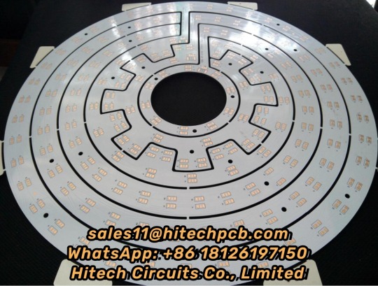
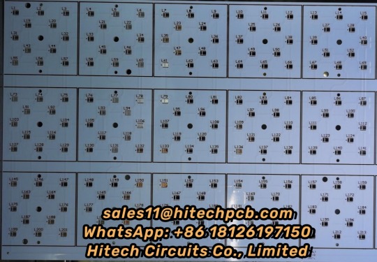
Aluminium PCB
1. What’s Aluminium LED PCB?
Aluminum LED PCB substrate is a metal - based copper-clad sheet with good heat dissipation. A single panel is generally composed of three layers of structure, namely the circuit layer (copper foil), insulation layer and metal base layer. It is commonly found in LED lighting products. There are two sides, the white side is used to weld the LED pins, and the other side is the natural color of aluminum, which is usually coated with heat-conducting gel and then in contact with the heat-conducting part. Among all metal core PCBS, Aluminum LED PCB is the most common type. The base material consists of an aluminum core and standard FR4. It features a thermal cladding that dissipates heat in an efficient manner while cooling components and improving the overall performance of the product. Currently, aluminum-backed PCBS are considered solutions for high power and tight tolerance applications.
2. Aluminum LED PCB with Copper Layer, Dielectric Layer & Aluminum Layer
Aluminum LED PCB has a similar layout to any other printed circuit boards with copper layer(s), solder mask layer(s) and silkscreen(s). Instead of having a fiberglass or plastic substrate, Aluminum LED PCB is made from metal core substrate, which consists of copper layer, dielectric layer and aluminum layer. This substrate is called as Aluminum based copper clad laminate (CCL). The glass reinforced and ceramic filled dielectric layer in-between copper layer and aluminum layer is very thin, but plays a very important role of electric insulation and thermal conductivity (because of minimum thermal resistance) from copper layer to aluminum base. The copper is etched into conductors and metal base is to withdraw thermal (/heat). The superior heat transfer capacity of Aluminum-based PCB helps cooling components while eliminating problems associated with managing fragile ceramics.
3. Thermal conductivity of Aluminium LED PCB
The general thermal conductivity of Aluminum LED PCB is 0.3, 0.6, 1.0, 1.5, 2.0, 3.0, 5.0, 122W/m.k, etc., among which 0.3-1.0w /m.k is the general conductive Aluminum LED PCB, 1.5W/m.k is the middle conductive Aluminum LED PCB, 2.0-3.0w /m.k is the high conductive Aluminum LED PCB. 5.0W/m.k is thin abasal substrate, and 122W/m.k is ultra-high conductivity Aluminum LED PCB, also known as ALC Aluminum LED PCB.
At present, the common Aluminum LED PCB on the market has a thermal conductivity of 1.0, 1.5, 2.0W/m.k high conductivity type Aluminium LED, wherein the thermal conductivity of 1.0W/m.k Aluminum LED PCB is called general Aluminum LED PCB, its insulation layer is composed of epoxy glass cloth bonded sheet; Aluminum LED PCB with thermal conductivity of 1.5W/m.k is called high heat dissipation Aluminum LED PCB, and its insulation layer is composed of epoxy resin or other resins with high thermal conductivity; The Aluminum LED PCB with a thermal conductivity of 2.0W/m.k is called the Aluminum LED PCB for high-frequency circuit, and the insulating layer is composed of polyolefin resin or Polyimide resin glass cloth bonded sheet. The thermal conductivity of Aluminum LED PCB varies according to the copper layer in the circuit. Different processes produce different levels of thermal conductivity.
We currently support Aluminum based CCLs from Ventec, GDM and BoYu with thermal conductivity from 1.0 ~ 7 W/m•K. The Aluminum LED PCB prices of Ventec is much higher than that with GDM and BOYU since material cost, and the prices of high thermal conductivity is higher than low thermal conductivity. Hitechpcb provides a wide range of electrical and thermally conductive interface pads, thermally conductive gap filler, thermal phase change materials and thermally conductive electrically insulating materials, as well as specialized equipment for high volume Aluminum LED PCB manufacturing. Choosing Hitech Circuits PCB as your Aluminum LED PCB supplier, just send your Gerber files and fabrication notes to us, we will deliver qualitied PCB boards to you on time.
4. Dielectric Constant of Aluminium LED PCB
The dielectric constant of Aluminum LED PCB substrate is a special detection method for Aluminum LED PCB. It is a variable Q value series resonance method through the measurement of dielectric constant and dielectric loss factor. The sample and tuning capacitor are connected in series to the high frequency circuit to measure the series circuit The principle of Q value.
The performance of Aluminum LED PCB includes requirements such as peel strength, surface resistivity, minimum breakdown voltage, dielectric constant, flammability and thermal resistance.
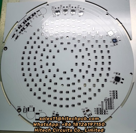
5. Aluminum LED PCB with White Solder Mask
The retail price of Aluminum LED lights has dropped dramatically in recent years, while the energy efficiency and brightness of LED lights have improved. These technological advances have led some to predict annual growth of 45% over the next five years. With the development of the LED industry, the demand for LED PCBS and solder masks is also increasing. Solder shield is a protective coating applied to exposed printed circuit boards. The exposed PCB board is covered with a mask to prevent accidental solder bridging during PCB assembly and to protect the PCB from the environment. Solder masks are traditionally green, and are expected to withstand the high temperatures that occur in reflow soldering, as different colors such as blue, red, or black will occasionally appear. Increased production of Hitch Aluminum LED PCB requires increased whiteness and color stability of the mask. Aluminum LED PCB commonly used LPI welding color is white and black, of which white welding color is the most commonly used to achieve high brightness and perfect light reflection. White Aluminum LED PCB ensures no darkening and will not affect the color temperature of LED smd. At the same time, it also helps to increase the life of LED applications. Looking for reliable Aluminum LED PCB suppliers, Hitech is a good choice.
6. Classification of Aluminum LED PCB Substrate
Aluminum LED PCB-based copper clad plates are divided into three categories:
The first is the universal aluminum-based copper clad plate, the insulation layer is composed of epoxy glass cloth bonded sheet;
The second is the high heat dissipation aluminum-based copper-clad plate, the insulation layer is composed of high thermal conductivity epoxy resin or other resins;
Third, high frequency circuit aluminum base copper plate, insulation layer by polyolefin resin or Polyimide resin glass cloth bonded sheet.
The biggest difference between aluminum clad copper plate and conventional FR-4 clad copper plate is heat dissipation. Compared with 1.5mm thickness of FR-4 clad copper plate and aluminum clad copper plate, the former thermal resistance of 20 ~ 22 ℃, the latter thermal resistance of 1.0 ~ 2.0℃, the latter is much smaller.
7. Aluminum LED PCB Performance:
(1) Heat dissipation
Many double panel, multi - layer plate high density, power, heat distribution is difficult. Conventional printed board substrates such as FR4, CEM3 are bad conductors of heat, insulation between layers, heat does not escape. Local heating of electronic equipment is not excluded, leading to high temperature failure of electronic components, and Aluminum LED PCB can solve this problem of heat dissipation.
(2) Thermal Expansibility
Thermal expansion and cold contraction is the common nature of substances, and the coefficient of thermal expansion of different substances is different. Aluminum based printed board can effectively solve the problem of heat dissipation, so that the printed board components of different substances on the thermal expansion and contraction problem, improve the durability and reliability of the whole machine and electronic equipment. Especially solve SMT (surface mount technology) thermal expansion and shrinkage problems.
(3) Dimensional stability
Aluminum-based printed boards are obviously much more stable in size than those made of insulating materials. Aluminum base printed board, aluminum sandwich board, heating from 30℃ to 140~150℃, the size change is 2.5~3.0%.
(4) Other reasons
Aluminum based printed board, with shielding effect; Instead of brittle ceramic substrate; Safe use of surface mounting technology; Reducing the real effective area of the printed board; Instead of radiator and other components, improve the heat resistance and physical properties of products; Reduce production costs and labor.
8. Why choose Aluminum LED PCB from Hitechpcb? What are the advantages of Aluminum LED PCB?
(1) Good heat dissipation performance: Aluminum LED PCB can reduce the thermal resistance to the minimum, has a smaller thermal resistance, thermal expansion coefficient is closer to copper foil, so that Aluminum LED PCB has excellent thermal conductivity and heat dissipation performance, reduce the module operating temperature, prolong the service life.
High current load: Using the same thickness, the same line width, Aluminum LED PCB substrate can carry higher current.
(2) Good machinability: can replace ceramic substrate, better mechanical endurance. At the same time, high strength and toughness, can realize large area printed board manufacturing and component mounting.
(3) Good electromagnetic shielding: In order to ensure the performance of electronic circuits, some components of electronic products need to prevent electromagnetic radiation and interference. Aluminum LED PCB can act as a shield plate, play the role of shielding electromagnetic wave
(4) Environmental protection: The Aluminum LED PCB used in the raw material is non-toxic and can be recycled. Meet RoHs requirements.
(5)Light weight: Aluminum LED PCB has a surprisingly light weight with excellent strength and elasticity, which is very convenient.
Hitech Circuits can provide high quality and affordable Aluminum LED PCB products for you.
9. Technical requirements for Aluminum LED PCB
The main technical requirements are:
1. Dimensional requirements: including panel size and deviation, thickness and deviation, perpendicularity and warpage; Appearance, including cracks, scratches, burrs and delimitation, aluminum oxide film, etc.
2. Performance requirements, including peel strength, surface resistively, minimum breakdown voltage, dielectric constant, combustion and thermal resistance requirements.
10. Special test method for Aluminum-based copper clad plates
One is the measurement method of dielectric constant and dielectric loss factor. It is the series resonance method with variable Q value. The sample and tuned capacitor are connected to the high-frequency circuit in series to measure the Q value of the series circuit.
The other is the measurement method of thermal resistance, which is calculated by the ratio of temperature difference and heat conduction between different temperature measurement points.
11. The Aluminum LED PCB manufacturing process in Hitechpcba
(1)Substrate cutting
a. cutting process: material → cutting
b. Note: ① Check the size of the first piece; ② Pay attention to Aluminum surface scratching and copper surface scratching; ③ Pay attention to the layering of the board edge and the tip.
(2)Plate drilling
a, drilling process: pin → drilling → inspection plate
b, matters needing attention: ① check the number of drilling holes, the size of the empty chestnut chain; ② Check the plate burr, hole deviation; ③ Avoid scratching the substrate; ④ Check and replace the drill nozzle.
(3) Imaging transfer
a, graphic imaging process: grinding plate → film → exposure → development
b, precautions: ① Check whether there is an open circuit after development; ② Pay attention to the poor line caused by the board wipe; ③ There can be no air residual exposure to prevent poor exposure; ④ Whether there is deviation in developing counterpoint; ⑤ After exposure, the development should be done at rest for more than 15 minutes.
(4)Solder mask and Silkscreen process
a, kill row silk printing resistance welding, character process: screen printing → pre-baking → exposure → development → character
b, matters needing attention: ① Check whether there is foreign body on the board; ② Pay attention to the cleaning of the net board; ③ Pre-bake for more than 30 minutes after screen printing, to avoid bubbles in the line; ④ Pay attention to the thickness and uniformity of screen printing; ⑤ After the pre-baked plate to completely mutual cooling, avoid touching film or damage to the ink surface gloss.
(5)E-test or flying probe test
a, test process: line test → withstand voltage test
b, precautions: ① How to distinguish after the test how to store qualified and unqualified products.
(6)FQC, FQA, packaging, shipping
a. Process: FQC→FQA→ Packaging → shipping
b. Note: ① FQC should pay attention to the confirmation of the appearance of the finished Aluminum LED PCB in the process of eye inspection and make a reasonable distinction; ② FQA does spot check and verify the inspection standards of FQC; ③ We should confirm the number of packages to avoid mixed plates, wrong plates and package
12. Application of Aluminum LED PCB
1. Audio devices: input, output amplifier, balance amplifier, audio amplifier, preamplifier, power amplifier.
2. Power Supply: switching voltage regulator, DC/AC converter, SW voltage regulator, etc.
3. Communication electronic equipment: high frequency amplifier, filter, transmitter circuit
4. Office automation equipment: motor drive, etc
5. Automobile: electronic regulator, ignition device, power controller, etc.
6. Computer :CPU board, floppy disk drive, power equipment, etc.
7. Power module: converter, solid relay, rectifier bridge, etc
8. Lamps and lighting: A variety of colorful LED energy-saving lamps are well received by the market, and Aluminum LED PCB used in LED lights has also begun to be applied on a large scale.
13. Aluminum LED PCB Storage Conditions
Aluminum LED PCB are generally stored in a dark and dry environment. Most Aluminum LED tube lighting metal core pcb are prone to dampness, yellowing, and blackening. Generally, they should be used within 48 hours after opening the vacuum package.
14. Specification for the manufacture of Aluminum LED PCB
a. Aluminum LED PCB is often used in power devices, power density is high, so the copper foil is thicker. If copper foils over 3oz are used, the etching of thick copper foils requires engineered line width compensation, otherwise the line width will be out of tolerance after etching.
b. The aluminum base surface of aluminum substrate must be protected by protective film in advance during PCB processing, otherwise, some chemicals will etch the aluminum base surface, resulting in appearance damage. And the protective film is easy to be hurt, resulting in gaps, which requires the whole PCB processing process must be inserted.
c. The hardness of the milling cutter used by the glass fiber board gong board is relatively small, and the hardness of the milling cutter used by the aluminum substrate is large. In the process of manufacturing glass fiber board milling cutter speed, while the production of aluminum substrate is at least two thirds slower.
d, computer milling glass fiber board is just the use of the machine's own cooling system, but the processing of aluminum substrate must be in addition to alcohol heat dissipation for the gong head.
15. Aluminum LED PCB circuit fabrication
(1) Mechanical processing: Drilling of aluminum substrate can be done, but no burr is allowed on the edge of the inner hole after drilling, which will affect the pressure test. Milling the shape is very difficult. And punching shape, need to use advanced mold, mold production is very skilled, as one of the difficulties of aluminum substrate. After shape punching, the edge should be very neat, without any burr, and do not hurt the welding resistance layer on the edge of the plate. Usually the use of soldier die, hole from the line, shape from the aluminum surface, circuit board punching force is cut down, and so on are skills. After punching the shape, the warpage of the board should be less than 0.5%.
(2) The whole production process is not allowed to wipe the aluminum base surface: aluminum base touch, or by a certain chemical will produce surface discoloration, blackening, which is absolutely unacceptable, re-polishing aluminum base some customers do not receive, so the whole process does not touch the aluminum base surface is one of the difficulties in the production of aluminum base plate. Some enterprises use passivation process, some in hot air leveling (spray tin) before and after each pasted protective film.
(3) Over-high voltage test: the aluminum base board of the communication power supply shall be tested at 100% high voltage. Some customers require direct current or alternating current. The voltage shall be 1500V or 1600V, and the time shall be 5 seconds or 10 seconds. Dirt on the board, holes and aluminum edge burr, line saw tooth, damage to any little insulation layer will lead to high voltage test fire, leakage, breakdown. Pressure test board stratification, foaming, are rejected.
1 note
·
View note
Text
Heavy Copper PCB: Power Up Your Electronics with Thick Copper Boards

When it comes to powering up electronics, one of the most important components is the Printed Circuit Board (PCB). And when it comes to heavy-duty applications that require high power, thick copper PCBs are the way to go. These specialized boards are designed to handle larger currents and dissipate heat more efficiently than standard PCBs.
One popular type of heavy copper PCB is made from FR4, a type of fiberglass-reinforced epoxy laminate. With a board thickness of 1.6mm, these boards can handle current levels ranging from 2 to 12oz, making them ideal for a wide range of applications.
To ensure reliable performance and longevity, the boards are surface-treated with immersion gold. This coating protects against corrosion and helps ensure good conductivity.
When it comes to payment and delivery terms, customers have a variety of options. Payment can be made through L/C, T/T, or WesternUnion. Delivery terms include DDU, FOB, CFA, CIF, CPT, and EXW. This flexibility makes it easy for customers to find a payment and delivery arrangement that suits their needs.
In terms of certifications, these heavy copper PCBs have been tested and certified for use in a wide range of applications. They meet UL Consumer (Wear, Electronic Digital, Household Appliances, Connectors), Industrial Control, Automobile TS16949, Medical, Server, Cloud Computing & Base Station, Aviation, Military, and Communication standards. This means that they are suitable for use in everything from household appliances to military equipment.
In conclusion, if you need a PCB that can handle heavy-duty power applications, look no further than heavy copper PCBs. With their FR4 material, 1.6mm thickness, and surface treatment of immersion gold, these boards are designed for reliable performance and longevity. And with a range of payment and delivery options, they are easy to acquire and integrate into your project.
0 notes
Text
Filament Issues in an Ampeg SVT Classic
A customer recently brought me an Ampeg SVT Classic that was sounding weak and lifeless.
Though I am not especially fond of working on them, I do have a lot of experience with SVT heads, especially the earliest version with 6146B power tubes, and the second version with 6550s. I have gotten quite adept at patching the holes burnt in their circuit boards when they arc.
For a few weeks in 1992, I had to do this almost every night while helping-out on Keith Richards “Main Offender” recording sessions at a studio called “The Site” in Marin County, California. All of Keith’s and Charley Drayton’s bass tracks were recorded with a 1969 SVT using 6146B tubes. Every night while recording, they would blow at least one 6146B, which would, in turn, create a hole or two in the circuit board of the amp.
So, each day, while the band slept, I would replace the offending tube(s), patch the hole(s) with FR4 (the fiberglass/epoxy material the boards are made of), replace the burnt traces with carefully bent copper wire, glue them in place with epoxy and insulate them with RTV, so that the amp was ready for that night’s recording. My patched areas never burnt again, but there was plenty of original area still, to die a fiery death. Madness, pure madness.
I should mention that I was not permitted to modify the circuit for greater reliability, as they liked the way it sounded, and were afraid it would change the sound if I made my recommended changes to keep it from blowing up so spectacularly.
But I digress.
Back to the SVT Classic on my bench. The owner said that it would sometimes sound OK, but would get much weaker over the course of the night, and that sometimes it would be weak sounding as soon as it was turned on. First off, I made sure that the recommended updates to the circuit had been made, which they had at the factory.
Initially I suspected mis-biased tubes, but the real culprit was the connection between the filament wires from the power transformer and the power tube board itself. Ampeg’s designers chose to use push-on connectors rather than solder, in the interest of easier assembly and repairs. The connectors had clear silicone boots for electrical insulation, and the boots were badly discolored and burnt from the heat generated by the resistance in the connection.
I measured the filament voltage on both sides of the connectors. I got a steady 6.3 VAC on the transformer side. On the board side though, due to the resistance in the connection, the voltage started at 6.0 VAC and, over the course of an hour, slowly dropped to 5.1 VAC. All this voltage loss was due to the resistance in the female connectors’ friction contact with the tabs on the board. No wonder the amp was sounding lifeless!

I measured the filament voltage on both sides of the connectors. I got a steady 6.3 VAC on the transformer side. On the board side though, due to the resistance in the connection, the voltage started at 6.0 VAC and, over the course of an hour, slowly dropped to 5.1 VAC. All this voltage loss was due to the resistance in the connection itself. No wonder the amp was sounding lifeless!
Power loss due to a resistive contact is a vicious cycle. A little bit of resistance in the contact causes a little bit of heat to develop. As the connection heats up, its resistance increases, causing still more resistance, and so it continues. Eventually it can get hot enough to burn the board, melt the wire’s insulation, or melt the solder, causing the tab to fall out of the board altogether. Additionally, the heat increases the electron activity in the metal, making it more reactive, causing accelerated oxidation, which, in turn increases resistance, and adds to this whole nasty mess.
My solution was to remove the push-on connectors from the wires, strip the insulation back, tin the wires appropriately, slide on two lengths of thick 3-1 heat shrink tubing, and then solder the wires firmly to the tabs, making sure to have good, flowing, filleted solder joints for maximum current flow and minimum resistance.

I measured the voltage at the tabs and at the tube sockets, and they both remained steady at 6.3 VAC for over an hour, with no drop in the voltage. Success!
Then it was a matter of pushing the heat shrink tubing over the tabs, shrinking them with a heat gun, and putting the amp back together.

It is worth pointing out that the push-on connectors that Ampeg used were rated for well in excess of the current that they were seeing. These connectors were rated by their manufacturer for 15 amperes of continuous current and 30 amperes of intermittent current. So, any recent engineering school graduate would feel that they were doing good, robust design work by specifying these in the amplifier. This is a good example of why there is no substitute for adult supervision in the design process. Someone who has been working on amplifiers for a half century would look at that and say that while the connector did not technically fail, it did create a serious problem for the amp it was used in.
Resistance in low-current connections is seldom a problem, but in high-current, low-voltage connections like the filaments of an SVT, where they carry 9.6 amperes, resistance in a killer. A loss of 1.2 volts in a 200-volt supply would usually be insignificant, but a loss of 1.2 volts in this 6.3-volt supply was very much a serious problem.
2 notes
·
View notes
Text
Safety Advantages of Using FR4 Epoxy Fiberglass Board as Insulation Material

View On WordPress
0 notes
Text
Why choose PCBA for custom PCB assembly in 2022
PCB Terminology: Definitions You Can Use There’s a lot more to PCB design terminology than PCB vs. PCBA. Here’s key PCB terminology to become familiar with:
Double-sided PCB: also known as a two-layer PCB, a double-sided PCB features components for connectivity on both sides.
Flexible PCB: a flexible printed circuit board is designed to move and bend to accommodate the design of the device. Flexible PCBs provide OEMs with more compact, lightweight and customizable solutions to suit their needs.
FPGA: a field-programmable gate array (FPGA) is an integrated circuit that can be programmed to execute one or more operations.
FR4: low-cost printed circuit board material commonly used for the substrate layer. FR4 is made from fiberglass cloth that has been embedded in epoxy resin. The term FR4 is a type of substrate, and also the rating used grade epoxy laminate sheets.
Gerber File: computer-aided manufacturing (CAM) file used to provide an industry standard for communicating board specifications with multiple manufacturers.
Light engine: similar to a PCBA, a light engine is a small board that contains a combination of LED modules and an LED driver.
Multi-layer PCB: a board that features more than two conductive metal layers. Multi-layer PCBs enable a range of interconnections ideal for many applications and industries.
Pad: the connection point for the electronic component terminal in the PCB. Components are soldered to the pad.
Rigid PCB: the opposite of a flexible PCB, a rigid circuit board made of a solid substrate material such as metal or FR4 that can not bend. Depending on the design of the device, rigid PCBs can be the most cost-effective solution for mass production.
Single-sided PCB: a simple board with electronic connections on one side.
SMT Pick and Place Machine: High-speed, automated equipment used to place surface-mount technology (SMT) devices onto a printed circuit board. These machines are highly precise and efficient, helping reduce the costs of PCB production.
Solder Paste Printing: using a printer and a stencil, solder paste is applied to a PCB and baked in an oven to seal the bond.
Substrate: the material used to create the foundation of the PCB. This base material is usually made of fiberglass, but can also be comprised of epoxy, metal, ceramic or other materials. The material selection of the substrate is dictated by the primary function and design of the PCB and its components.
Stencils: used to aid the application of solder paste to surface mount (SMT) component pads during the printed circuit board assembly (PCBA).
Wave Solder Machine: wave soldering is a bulk soldering process used in the manufacture of printed circuit boards. The wave solder machines move each board into a pan where a wave of melted solder covers it, bonding all the components of the board together.
https://www.kingfordpcb.com/technology-blog/why-choose-pcba-for-custom-pcb-assembly-in-2022/
0 notes
Text
PCB and its components - Electronics Designer and Manufacturer
Accept in yourself!!....... on the off chance that mechanical advancement never exists, what had been occurred in your life?........probably, we don't have the foggiest idea about the lifestyle, we going to live. We can't envision the existence without electronic gadgets briefly as of now, since we utilizing the various electronic gadgets in our daily schedule, which are uncountable. Just as it involved a position, that we can't supplant anybody.

Some of them are PCs/PC, cell phones, ATM, pen-drive, TV, distant and so on. In spite of the fact that individuals considering the term electronics designer and manufacturer a straightforward one or nothing, yet it displays and models the new way for every single field through the specialized systems.
Determination of Electronics
The word electronics is gotten from "electron mechanics", which implies to consider the conduct of electron and the various conditions applied in the electric field. Coordinating the progression of electrons in gadget called electronic gadget.
These gadget plays out the significant job in assembling of electronic circuits. The electric flow is produced from the movement of electrons through the conduit and can be handled with the help of batteries and generators.
Parts of electronic gadgets
• Analog electronics
• Digital electronics
• Integrated circuit
• Micro electronics
• Nano electronics
• Semiconductor gadget
What is PCB and it's parts?
PCB is entitled under the computerized electronics, which is vital in electronics designer and manufacturer field. Normally, Printed Circuit Board is only a plain board, that alludes to the motherboard. A few parts have been mounted or appended on the PCB, are computer chips, resistors, capacitors, connectors. Certain parts like presentation or camera, not straightforwardly mounted on the PCB, yet seldom appended to the PCB through a bunch of mating connectors and a level link.
The dull surface in the PCB are conductive wires. The remainder of the surfaces are non-conductive protectors, which are woven fiberglass with an epoxy tar fastener named as FR4.
A framework on chip or SoC is mounted on a matrix of association focuses or cushions called a ball network cluster, which is critical for developing the PCB. Extra lattice set for different CPUs, similar to memory chip and remote chip just as resistors, capacitors and different components.
So, the PCB permits every one of the parts to speak with the SoC just as different micro processors through many wires and rather exact association.
How do Printed Circuit Board functions?
While riding the google for the printed circuit board, presumably, we ready to seen the green shading board. It is built of multifaceted maze of many copper wires. Printed Circuit Board gives design and association to every one of the parts, that has been mounted on a superficial level. Wire on the center, empowers each part to convey and cooperate.
#electronics desginer#electronics manufactures#electronic manufacturing company#electronics manufacturing companies
0 notes
Text
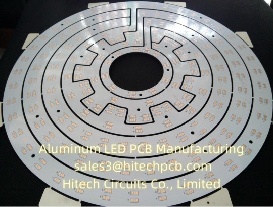
What’s Aluminium LED PCB?
Aluminum LED PCB substrate is a metal - based copper-clad sheet with good heat dissipation. A single panel is generally composed of three layers of structure, namely the circuit layer (copper foil), insulation layer and metal base layer. It is commonly found in LED lighting products. There are two sides, the white side is used to weld the LED pins, and the other side is the natural color of aluminum, which is usually coated with heat-conducting gel and then in contact with the heat-conducting part. Among all metal core PCBS, Aluminum LED PCB is the most common type. The base material consists of an aluminum core and standard FR4. It features a thermal cladding that dissipates heat in an efficient manner while cooling components and improving the overall performance of the product. Currently, aluminum-backed PCBS are considered solutions for high power and tight tolerance applications.
2. Aluminum LED PCB with Copper Layer, Dielectric Layer & Aluminum Layer
Aluminum LED PCB has a similar layout to any other printed circuit boards with copper layer(s), solder mask layer(s) and silkscreen(s). Instead of having a fiberglass or plastic substrate, Aluminum LED PCB is made from metal core substrate, which consists of copper layer, dielectric layer and aluminum layer. This substrate is called as Aluminum based copper clad laminate (CCL). The glass reinforced and ceramic filled dielectric layer in-between copper layer and aluminum layer is very thin, but plays a very important role of electric insulation and thermal conductivity (because of minimum thermal resistance) from copper layer to aluminum base. The copper is etched into conductors and metal base is to withdraw thermal (/heat). The superior heat transfer capacity of Aluminum-based PCB helps cooling components while eliminating problems associated with managing fragile ceramics.
3. Thermal conductivity of Aluminium LED PCB
The general thermal conductivity of Aluminum LED PCB is 0.3, 0.6, 1.0, 1.5, 2.0, 3.0, 5.0, 122W/m.k, etc., among which 0.3-1.0w /m.k is the general conductive Aluminum LED PCB, 1.5W/m.k is the middle conductive Aluminum LED PCB, 2.0-3.0w /m.k is the high conductive Aluminum LED PCB. 5.0W/m.k is thin abasal substrate, and 122W/m.k is ultra-high conductivity Aluminum LED PCB, also known as ALC Aluminum LED PCB.
At present, the common Aluminum LED PCB on the market has a thermal conductivity of 1.0, 1.5, 2.0W/m.k high conductivity type Aluminium LED, wherein the thermal conductivity of 1.0W/m.k Aluminum LED PCB is called general Aluminum LED PCB, its insulation layer is composed of epoxy glass cloth bonded sheet; Aluminum LED PCB with thermal conductivity of 1.5W/m.k is called high heat dissipation Aluminum LED PCB, and its insulation layer is composed of epoxy resin or other resins with high thermal conductivity; The Aluminum LED PCB with a thermal conductivity of 2.0W/m.k is called the Aluminum LED PCB for high-frequency circuit, and the insulating layer is composed of polyolefin resin or Polyimide resin glass cloth bonded sheet. The thermal conductivity of Aluminum LED PCB varies according to the copper layer in the circuit. Different processes produce different levels of thermal conductivity.
We currently support Aluminum based CCLs from Ventec, GDM and BoYu with thermal conductivity from 1.0 ~ 7 W/m•K. The Aluminum LED PCB prices of Ventec is much higher than that with GDM and BOYU since material cost, and the prices of high thermal conductivity is higher than low thermal conductivity. Hitechpcb provides a wide range of electrical and thermally conductive interface pads, thermally conductive gap filler, thermal phase change materials and thermally conductive electrically insulating materials, as well as specialized equipment for high volume Aluminum LED PCB manufacturing. Choosing Hitech Circuits PCB as your Aluminum LED PCB supplier, just send your Gerber files and fabrication notes to us, we will deliver qualitied PCB boards to you on time.
4. Dielectric Constant of Aluminium LED PCB
The dielectric constant of Aluminum LED PCB substrate is a special detection method for Aluminum LED PCB. It is a variable Q value series resonance method through the measurement of dielectric constant and dielectric loss factor. The sample and tuning capacitor are connected in series to the high frequency circuit to measure the series circuit The principle of Q value.
The performance of Aluminum LED PCB includes requirements such as peel strength, surface resistivity, minimum breakdown voltage, dielectric constant, flammability and thermal resistance.
5. Classification of Aluminum LED PCB Substrate
Aluminum LED PCB-based copper clad plates are divided into three categories:
The first is the universal aluminum-based copper clad plate, the insulation layer is composed of epoxy glass cloth bonded sheet;
The second is the high heat dissipation aluminum-based copper-clad plate, the insulation layer is composed of high thermal conductivity epoxy resin or other resins;
Third, high frequency circuit aluminum base copper plate, insulation layer by polyolefin resin or Polyimide resin glass cloth bonded sheet.
The biggest difference between aluminum clad copper plate and conventional FR-4 clad copper plate is heat dissipation. Compared with 1.5mm thickness of FR-4 clad copper plate and aluminum clad copper plate, the former thermal resistance of 20 ~ 22 ℃, the latter thermal resistance of 1.0 ~ 2.0℃, the latter is much smaller.
6. Aluminum LED PCB Performance:
(1) Heat dissipation
Many double panel, multi - layer plate high density, power, heat distribution is difficult. Conventional printed board substrates such as FR4, CEM3 are bad conductors of heat, insulation between layers, heat does not escape. Local heating of electronic equipment is not excluded, leading to high temperature failure of electronic components, and Aluminum LED PCB can solve this problem of heat dissipation.
(2) Thermal Expansibility
Thermal expansion and cold contraction is the common nature of substances, and the coefficient of thermal expansion of different substances is different. Aluminum based printed board can effectively solve the problem of heat dissipation, so that the printed board components of different substances on the thermal expansion and contraction problem, improve the durability and reliability of the whole machine and electronic equipment. Especially solve SMT (surface mount technology) thermal expansion and shrinkage problems.
(3) Dimensional stability
Aluminum-based printed boards are obviously much more stable in size than those made of insulating materials. Aluminum base printed board, aluminum sandwich board, heating from 30℃ to 140~150℃, the size change is 2.5~3.0%.
(4) Other reasons
Aluminum based printed board, with shielding effect; Instead of brittle ceramic substrate; Safe use of surface mounting technology; Reducing the real effective area of the printed board; Instead of radiator and other components, improve the heat resistance and physical properties of products; Reduce production costs and labor.
7. Why choose Aluminum LED PCB from Hitechpcb? What are the advantages of Aluminum LED PCB?
(1) Good heat dissipation performance: Aluminum LED PCB can reduce the thermal resistance to the minimum, has a smaller thermal resistance, thermal expansion coefficient is closer to copper foil, so that Aluminum LED PCB has excellent thermal conductivity and heat dissipation performance, reduce the module operating temperature, prolong the service life.
High current load: Using the same thickness, the same line width, Aluminum LED PCB substrate can carry higher current.
(2) Good machinability: can replace ceramic substrate, better mechanical endurance. At the same time, high strength and toughness, can realize large area printed board manufacturing and component mounting.
(3) Good electromagnetic shielding: In order to ensure the performance of electronic circuits, some components of electronic products need to prevent electromagnetic radiation and interference. Aluminum LED PCB can act as a shield plate, play the role of shielding electromagnetic wave
(4) Environmental protection: The Aluminum LED PCB used in the raw material is non-toxic and can be recycled. Meet RoHs requirements.
(5)Light weight: Aluminum LED PCB has a surprisingly light weight with excellent strength and elasticity, which is very convenient.
Hitech Circuits can provide high quality and affordable Aluminum LED PCB products for you.
0 notes
Text
The Journey of PCB Assembly: An Intricate Dance of Precision and Technology
Printed Circuit Board (PCB) assembly is the process of connecting electronic components with the wiring of printed circuit boards. This sophisticated process involves various steps, each crucial for ensuring the functionality and reliability of the final electronic product. From consumer electronics to industrial machinery, PCBs are the backbone of modern technology. In this blog, we will delve into the intricate journey of PCB assembly, highlighting key stages and the technologies involved.
Design and Prototyping
The journey of PCB assembly begins with design and prototyping. Engineers use software like Eagle, Altium Designer, or KiCad to create detailed schematics of the PCB. This design stage involves specifying the locations of components and the routing of electrical connections. The design is then translated into a physical prototype, often through rapid prototyping techniques such as 3D printing or CNC machining.
Material Selection
Selecting the right materials is critical for the performance and durability of the PCB assembly. The board itself is typically made from a fiberglass-reinforced epoxy laminate, known as FR4. The choice of copper thickness, solder mask, and surface finish (such as HASL, ENIG, or OSP) also plays a significant role in the board’s performance and cost.
PCB Fabrication
Once the design and materials are finalized, the PCB fabrication process begins. This involves several steps:
Layering: Multi-layer PCBs are constructed by stacking and bonding multiple layers of copper and insulating material.
Etching: Copper layers are etched to remove unwanted copper, leaving only the desired circuit patterns.
Drilling: Holes for component leads and vias are drilled with precision.
Plating: Holes are plated with copper to ensure electrical connectivity between layers.
Solder Mask and Silkscreen: A solder mask is applied to protect the copper traces, and a silkscreen is added to indicate component locations.
Component Placement
With the PCB fabricated, the next step is to place the electronic components onto the board. This process can be done manually for small-scale or prototype runs, but is typically automated using Surface Mount Technology (SMT) for larger production volumes. Automated Pick-and-Place machines accurately place components onto the PCB at high speeds.
Soldering
After component placement, the components must be securely attached to the board using solder. There are two primary methods for soldering:
Reflow Soldering: For SMT components, solder paste (a mixture of powdered solder and flux) is applied to the board, and then the entire board is heated in a reflow oven. The solder paste melts and solidifies, creating strong electrical and mechanical bonds.
Wave Soldering: For through-hole components, the board is passed over a wave of molten solder. The solder adheres to the exposed metal surfaces, forming connections.
Inspection and Testing
Ensuring the quality and functionality of the assembled PCB is paramount. Various inspection and testing methods are employed:
Automated Optical Inspection (AOI): AOI systems use cameras to inspect the PCB for defects such as missing components or solder bridges.
X-ray Inspection: X-ray machines can inspect hidden solder joints, especially useful for Ball Grid Array (BGA) components.
Functional Testing: This involves powering the PCB and verifying that it performs as expected under operating conditions.
Final Assembly and Packaging
Once the PCB passes inspection and testing, it may undergo final assembly, where additional components such as connectors, heatsinks, or enclosures are added. The completed product is then packaged, ready for shipping to customers or further integration into larger systems.
Conclusion
The journey of PCB assembly is a fascinating blend of design, materials science, precision engineering, and advanced manufacturing techniques. Each stage, from initial design to final testing, plays a crucial role in delivering reliable and high-performance electronic products. As technology continues to evolve, so too will the methods and tools used in PCB assembly, driving innovation and enabling the creation of increasingly sophisticated electronic devices. For more details visit our website www.crimpcircuits.com
#pcb manufacturing toronto#printed circuit board design#metal clad pcb#printed circuits#rigid flex pcb#full turnkey pcb services#turnkey pcb services#pcb parts#eagle software#pcb designing#flexible pcb#pcb assembly#printed circuit board manufacturers#pcb manufacturers in canada#circuit board manufacturers in canada#pcb quote#pcb prototype services in canada
0 notes
Text
Understanding the Basics of Rigid Circuits in Electronics
In the world of electronics manufacturing, rigid circuits play a fundamental role in the design and fabrication of printed circuit boards (PCBs). These circuits, also known as rigid PCBs, serve as the backbone of electronic devices and systems, providing a sturdy platform for mounting components and facilitating the flow of electrical signals. In this article, we'll explore the basics of rigid circuits, their construction, and their applications in various industries.
1. Construction of Rigid Circuits
Rigid circuits are typically composed of a rigid substrate material, such as fiberglass epoxy laminate, commonly referred to as FR4. The substrate provides mechanical support and insulation for the circuit traces and components mounted on the board. Copper traces are etched onto the substrate to create the conductive pathways that connect the various components and form the circuit. These traces are typically plated with solder to facilitate component attachment during assembly.
2. Types of Rigid Circuits
Rigid circuits come in various types and configurations to suit different applications and design requirements. Some common types of rigid circuits include:
Single-sided PCBs: These consist of a single layer of substrate material with copper traces on one side.
Double-sided PCBs: These have copper traces on both sides of the substrate, connected via plated through-holes or vias.
Multilayer PCBs: These consist of multiple layers of substrate material with copper traces sandwiched between them. The layers are interconnected via vias to create complex circuit designs with higher component density and improved signal integrity.
High-frequency PCBs: These are designed to operate at high frequencies and may incorporate specialized materials and construction techniques to minimize signal loss and impedance mismatch.
3. Applications of Rigid Circuits
Rigid circuits are used in a wide range of electronic devices and systems across industries. Some common applications include:
Consumer electronics: Rigid circuits are found in smartphones, tablets, laptops, and other consumer devices where compact size and high performance are essential.
Automotive electronics: Rigid circuits are used in automotive control systems, engine management systems, infotainment systems, and other vehicle components.
Industrial controls: Rigid circuits are employed in industrial automation equipment, machinery, robotics, and process control systems.
Aerospace and defense: Rigid circuits are utilized in avionics, navigation systems, communication systems, radar systems, and other aerospace and defense applications where reliability and performance are critical.
4. Advantages of Rigid Circuits
Rigid circuits offer several advantages over other types of circuit boards, including:
Mechanical stability and durability
Excellent electrical performance
Compatibility with surface mount technology (SMT)
Ease of assembly and testing
Cost-effectiveness for high-volume production
Conclusion
Rigid circuits are essential components in modern electronics, providing a robust platform for building complex electronic systems. With their versatility, reliability, and performance, rigid circuits continue to be a preferred choice for engineers and designers seeking high-quality solutions for their electronic designs. Whether in consumer electronics, automotive systems, industrial controls, or aerospace applications, rigid circuits play a vital role in powering the devices and technologies that shape our world.
1 note
·
View note