#Arduino usb host shield library
Explore tagged Tumblr posts
Visit Tumblr Blog
Explore Tumblr blogs with no restrictions, modern design and the best experience.
Last Seen Tumblr Blogs


Fun Fact
Tumblr was created by web developers David Karp and Marco Arment.
Text
Arduino-Compatible Boards: Mega 2560 Pro, LilyPad, and Nano
Arduino is a popular open-source hardware and software platform that is widely used for building a variety of electronic projects. The platform has a vast range of boards that are compatible with it, each with different features, capabilities, and price points. In this blog post, we will discuss three of the most popular Arduino-compatible boards: Mega 2560 Pro, LilyPad ATmega328P, and Nano Board R3.
Mega 2560 Pro:
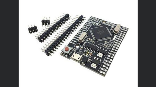
The Mega 2560 Pro is a powerful and versatile board that is designed for advanced projects. It has 54 digital I/O pins, 16 analog inputs, and 4 UARTs (hardware serial ports). It also has a USB host port that can be used to connect USB devices such as keyboards, mice, and game controllers. The board runs on the Atmel ATmega2560 microcontroller, which has a clock speed of 16 MHz. This makes it suitable for running complex programs and driving multiple sensors and actuators simultaneously.
LilyPad ATmega328P:
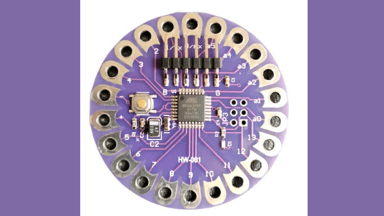
The LilyPad ATmega328P is a wearable board that is designed to be sewn onto clothing and other fabric surfaces. It is based on the Arduino platform and uses the same Atmel ATmega328P microcontroller as the Arduino Uno. The board has 14 digital I/O pins, 6 analog inputs, and can be powered by a 3.7V LiPo battery. It also has a built-in USB port for programming and debugging. The board is compatible with various LilyPad accessories, including sensors, LEDs, and buzzers.
Nano Board R3:

The Nano Board R3 is a compact and affordable board that is ideal for beginners and small projects. It has 22 digital I/O pins, 8 analog inputs, and can be powered via a USB cable or an external power source. The board runs on the Atmel ATmega328 microcontroller, which has a clock speed of 16 MHz. The Nano Board R3 has a built-in USB port for programming and debugging and is compatible with a range of shields and modules that can be used to expand its capabilities.
In conclusion, these three boards offer different features and capabilities, making them suitable for a wide range of applications. The Mega 2560 Pro is ideal for complex projects that require many I/O pins and high processing power. The LilyPad ATmega328P is perfect for wearable projects, while the Nano Board R3 is an excellent choice for beginners and small projects. Regardless of which board you choose, you can be sure that it will be compatible with the vast Arduino community and its extensive library of code and examples.
2 notes
·
View notes
Text
Arduino usb host shield library

#ARDUINO USB HOST SHIELD LIBRARY SERIAL#
#ARDUINO USB HOST SHIELD LIBRARY DRIVERS#
#ARDUINO USB HOST SHIELD LIBRARY PORTABLE#
#ARDUINO USB HOST SHIELD LIBRARY ANDROID#
#ARDUINO USB HOST SHIELD LIBRARY CODE#
Connecting docking station or other devices with TV and display epic picture up to 4K high definition. The package comes with one meter long HDMI wire with durable material. Same amount of ports for USB controllers and HDMI ports for TV.
#ARDUINO USB HOST SHIELD LIBRARY PORTABLE#
Replacement For Official Nintendo Switch Dock: This dock is only 48g(1.7 oz), which is much more portable and lightweight than official switch dock, ideal replacement for taking out anywhere.
Our switch docking station have professional technical support, after repeated testing, with the highest quality assurance! Built in smart original chip, having Short-circuit Protection, Over Power Protection, Recovery Protection and Overheating Protection.
Ventilation Holes Design & Smart Chip System: Oversized venting on both sides of the switch stand, so don't worry about ventilation holes will be blocked and affect equipment cooling.
We promise 100% satisfactory after-sales service,45 days unconditional refund, Up to 12 months warranty (repalcement) ,so that your purchase has no worries.
#ARDUINO USB HOST SHIELD LIBRARY ANDROID#
Built-in high sensitive smart touchpad with 360-degree flip design.Ideal for devices such as PC Laptop Raspberry Pi 2-3 MacOS Xbox 360 Xbox One PS3 PS4 Google Android TV Box HTPC IPTV and so on.For our i8+ 2.4G Wireless keyboard can work with Amazon Fire TV.Special Notice: if you want to use this keyboard with Amazon Fire TV 4K and Amazon Fire Stick you need to prepare a Micro USB host OTG cable.
Its operational range is up to 25 meters. And, it can be used as a remote replacement.
Wireless Remote Control: The keyboard can be connected to devices that have a standard USB interface using a mini receiver.
At the same time, it also looks like a really keyboard for PC or Notebook. There are 2 round polorus on the right and left side of the keyboard.
Game Handle Design: The mini wireless keyboard android is designed like a handle for game player.
Touchpad which supports multi-finger functions, A single finger click as left mouse function two-finger click as the right mouse function double finger drag as the rolling screen.
3 in 1 MultiFunction: 2.4GHz Mini Wireless QWERTY keyboard &TouchPad combo& LED backlit with USB interface adapter.
Lauszus on Teensy 3.0 now supported by the USB Host library.
Potts on Reading rotary encoder on Arduino PS Remote Controller Bluetooth stack by Cubexed
PTP and camera libraries repository on github.
Introduction to interfacing to cellphones.
Richard Ibbotson’s modified USB and PS3 library with extra NAK handling to be used with his PS3 and Nintendo game controller routines.
Legacy USB Host library, stable revision.
Hardware documentation – schematics, Eagle CAD files, PCB Gerbers.
#ARDUINO USB HOST SHIELD LIBRARY DRIVERS#
Mass Storage Class – USB flash drives, memory card readers, external hard drives/CD-ROMs, smartphones, etc.įuture plans include development drivers for communication devices, such as WiFi and cell phones, and support for other USB Host controllers.Xbox360 controller over wired USB as well as via a wirelss receiver.PTP with Canon EOS and Powershot extensions, as well as Nikon DSLR cameras.
#ARDUINO USB HOST SHIELD LIBRARY SERIAL#
USB to serial converters, including CDC ACM, Prolific PL2303 and FTDI FT232.The following device classes are currently supported: Current revision of the library (r2.0) supports MAX3421E host controllers, general USB functionality, enumeration of up to 44 devices with USB hub support, and MAX3421 GPIO pins access. The shield exists in configurations compatible with 5V and 3.3V Arduino boards.
#ARDUINO USB HOST SHIELD LIBRARY CODE#
The initial goal of the project was to develop Arduino code supporting USB Host controller in order to communicate with USB peripherals, such as keyboards, joysticks and cameras. This is a summary page for USB Host Shield project that I started in the spring of 2009. Primary target platform is Arduino, however, it can also be used with any other micro equipped with SPI interface. The board supports USB 2.0 full/low speed operation. USB Host Shield is an inexpensive ( $25 for the full-sized board and $20 for the Mini variant ) development board designed to be used in embedded applications which require USB Host functionality.
0 notes
Text
Arduino Brings USB Mouse to Homebrew computer
When building your own homebrew computer, everything is a challenge. Ultimately, that’s kind of the point. If you didn’t want to really get your hands dirty with the nuts and bolts of the thing, you wouldn’t have built it in the first place. For example, take the lengths to which [rehsd] was willing to go in order to support standard USB mice on their 6502 machine.
Code for mapping mouse movement to digital output.
The idea early on was to leverage existing Arduino libraries to connect with a standard USB mouse, specifically, the hardware would take the form of an Arduino Mega 2560 with a USB Host Shield. There was plenty of code and examples that showed how you could read the mouse position and clicks from the Arduino, but [rehsd] still had to figure out a way to get that information into the 6502.
In the end, [rehsd] connected one of the digital pins from the Arduino to an interrupt pin on the computer’s W65C22 versatile interface adapter (VIA). Then eleven more digital pins were connected to the computer, each one representing a state for the mouse and buttons, such as MOUSE_CLICK_RIGHT and MOUSE_LEFT_DOWN.
Admittedly, [rehsd] says the mouse action is far from perfect. But as you can see in the video after the break, it’s at least functional. While the code could likely be tightened up, there’s obviously some improvements to be made in terms of the electrical interface. The use of shift registers could reduce the number of wires between the Arduino and VIA, which would be a start. It’s also possible a chip like the CH375 could be used, taking the microcontroller out of the equation entirely.
From classic breadboard builds to some impressively practical portable machines, we’ve seen our fair share of 6502 computers over the years. Despite the incredible variation to be found in these homebrew systems, one thing is always the same: they’re built by some of the most passionate folks out there.
youtube
[Thanks to Jim for the tip.]
Arduino Brings USB Mouse to Homebrew computer was originally published on PlanetArduino
0 notes
Text
Barcode Scanner Interfacing with Arduino + USB Host Shield Module + 16x2 LCD Display
youtube
BarCode Scanner Interfacing with Arduino + USB Host Shield Module + 16x2 LCD Display. ****************************************************************** If You Want To Purchase the Full Project or Software Code Mail Us: [email protected] Title Name Along With You-Tube Video Link Project Changes also Made according to Student Requirements http://svsembedded.com/ è https://www.svskits.in/ M1: +91 9491535690 è M2: +91 7842358459 ****************************************************************** 1. usb host shield hardware manual, 2. usb host shield eagle, 3. usb host shield arduino mega 2560, 4. usb host mini v2, 5. symbol scanner raspberry pi, 6. stm32 barcode scanner, 7. sparkfun usb host shield, 8. serial barcode scanner Arduino, 9. sainsmart usb host shield, 10. raspberry pi zero handheld barcode scanner, 11. raspberry pi id scanner, 12. raspberry pi barcode scanner, 13. raspberry pi 3 scanner, 14. python usb barcode scanner, 15. python barcode scanner, 16. pjrc usb host, 17. opencv barcode reader c++, 18. oem barcode scanner, 19. mini usb host shield, 20. mini barcode scanner Arduino, 21. lv3096 Arduino, 22. how to connect usb barcode scanner to Arduino, 23. how does a barcode reader work, 24. esp8266 barcode scanner, 25. document scanner using Arduino, 26. diy barcode scanner, 27. circuitsathome, 28. circuits at home usb host shield, 29. beaglebone black barcode scanner, 30. barcode scanner with nodemcu, 31. barcode scanner using microcontroller, 32. barcode scanner schematic diagram, 33. barcode scanner module for raspberry pi, 34. barcode scanner module, 35. barcode scanner interfacing with arduino and usb host shield, 36. barcode scanner driver, 37. barcode scanner circuit diagram pdf, 38. barcode reader ic, 39. arduino usb shield, 40. arduino usb host shield ps3 controller, 41. arduino usb host shield example, 42. arduino usb host shield amazon, 43. arduino usb host shield, 44. arduino print barcode, 45. arduino mini usb host shield, 46. arduino barcode scanner library, 47. arduino barcode scanner amazon, 48. arduino barcode scanner, 49. adafruit usb host, 50. adafruit feather usb host, 51. adafruit barcode scanner,
0 notes
Photo


01.02.17
Happy New Year!
Carlos and I decided to postpone any printing due to the Holidays. Now that they’re over, the printing should happen this month. I’m still waiting to hear back from him.
Over the last month, I’ve researched and dug into the Internet trying to find out how to get a PS3 controller to communicate with an Arduino Uno over Bluetooth. I found that it is possible, but extremely difficult. Some people have done it and posted videos on Youtube (Here and here). So, I ordered a USB Host Shield and some Bluetooth dongles for my Uno, downloaded the USB Host Shield Library, and set to work experimenting. It was definitely a learning experience. I was able to get it to work for a few minutes, but something would always go wrong and it would lose the connection. I tried rewriting the code several times, but to no avail. That being said, the PS3 controller communicates perfectly over a USB cable. So, I’ve added a small USB port to the back of Wheatley. We’ll have to save wireless communication for a future upgrade (Maybe XBEE).
I also had the thought that plastic rubbing on plastic with pressure for an extended period probably wasn’t a good thing. I removed a little material from the Inner Socket’s Gimbal Mount to accommodate a Thrust Bearing (Represented by the blue ring in the pictures). This will help with the movement as well. I’ve also picked up several other parts and items in preparation for the coming build.
One last minor note: I start college a week from today. That may slow things down significantly. However, I promise that I will finish this project. I’ve invested too much time and money not to. Here’s looking forward to the future!
More Details Here
#new years push#animatronic wheatley#animatronics#3d design#3d printing#robots#robotics#arduino#ps3 controller#bluetooth#xbee#aperture laboratories#portal 2#wheatley
12 notes
·
View notes
Text
Something awesome update 4:
So after a whole night of troubleshooting I was able to finally get something running that acted as a key logger. I found out that there was a problem with how my keyboard was interacting with my computer. I realised after testing the example libraries with my mouse, which showed that there was no problem with my usb host shield as input was being detected when the mouse was plugged in. I borrowed my friends keyboard and I was finally getting some response!
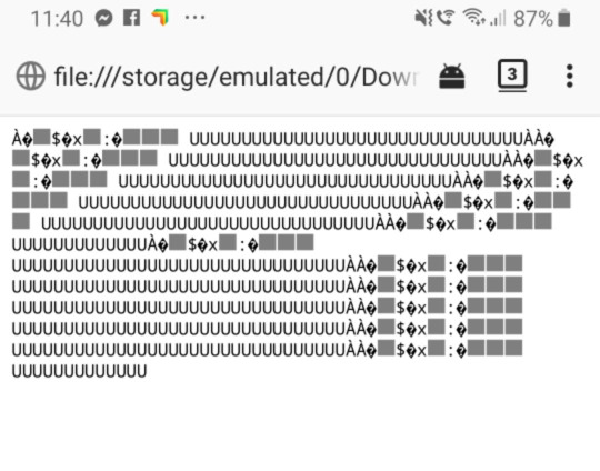
I reflashed my ESP module multiple times after watching a wide range of YouTube videos explaining how to correctly flash an ESP, and after doing so I was able to download a keystrokes.txt file. I thought that the device was fully functioning... but when I opened the txt file it was all gibberish. Quite frustrating but at least it was progress.
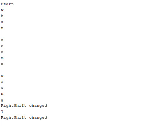
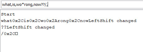
I decided to change my method of attack and instead of using the WiFi module I would instead just have the keystrokes printed in the serial monitor within the arduino IDE. This seemed more effective and I was actually getting some keys logged. The main problem was that it was printing them out individually one character per line, which isn’t very useful information when trying to read whole sentences.
Another problem that I had that they keys were not being passed through correctly, which meant that if you typed onto the keyboard, nothing would be typed onto the computer. This is obviously a problem as no one is going to be tricked into typing any information if they don’t see their keystrokes on the screen.
So I began working towards fixing that and ran into a problem with special keys like space and return, where the correct keystroke was not being pressed. It was instead putting ,,,, commas in substitute for space which was obviously a problem.
I could feel that I was close and after adding some edge cases for keys outside of the letter range, was able to get the keylogger functioning in a way that it could be useful. (sorry for filming in vertical)
youtube
I’m glad that I actually got something working in the end...
0 notes
Text
Something Awesome: First Setback
It seems like I have encountered my first challenge for the assignment. I have installed the required libraries to run the code from the repo I am currently using as a guide, and have successfully flashed the software to the Arduino Leonardo and ESP8266 chip. However, my keyboard lights up only for a split second, and no detectable WiFi signal is found.
I suspect that it might be because some of the pins under the USB host shield are not contacting the Arduino properly, so I will have to find a way to shorten the pins under the USB host shield, or rely on leads to connect the Arduino and USB host shield.

0 notes
Text
Polish company Husarion launched CORE2 — its second generation robot hardware controller for rapid prototyping and development. CORE2 is compatible with ROS, relies on an RTOS-based open-source software framework, and can be programmed with free tools either via cloud or offline. The controller is also compatible with other building platforms such as LEGO Mindstorms or Makeblock via optional modules.
CORE2 and CORE2-ROS boards side by side | Image credit: Husarion
CORE2 was showcased earlier this year at the Hannover Messe trade fair, and just like previous generation it is part of Husarion’s robotic development platform which is focused on making robot building more accessible for everyone.
What can Husarion CORE2 do?
CORE2 comes in two flavors. There’s the standalone low-power real-time connected computer with on-board ESP32 WiFi module for energy efficient or cloud-based projects.
Robot Operating System
CORE2-ROS harvests the processing power of an attached single-board computer such as the Raspberry Pi 3 or ASUS Tinker Board, while retaining real-time capabilities. This combo can run an Ubuntu based ROS image and lets you develop more advanced projects such as the ROSbot autonomous robot.
Everything is on-board, this makes things easy primarily because no additional hardware shields or interfaces are required for connecting motors or sensors. There are 4 DC motor ports with integrated H-bridges, 6 servo interfaces, a DC/DC converter for selecting voltage independently for each servo, 42 I/O pins, WiFi and other communication interfaces.
Husarion CORE2 robot controller | Image credit: Husarion
CORE2 is compatible with Arduino libraries — for every sensor or peripheral you want to connect there’s already a library written for it you can use without modifications.
Real-time processing. CORE2 controllers do not use up CPU cycles for high frequency data polling, relying instead on dedicated timers, DMA channels and interrupts, all driven by a RTOS (real-time operating system) and optimized libraries.
CORE2brick is an optional add-on interface and accessory kit for easily connecting LEGO Mindstorms hardware, accepting 4 LEGO motors and 6 LEGO sensors.
CORE2 servo controller module can control up to 12 servos delivering a selectable output voltage of 5-8.6 V, and 4 A maximum current. Each CORE2 or CORE2-ROS accepts up to 4 such servo controllers.
CORE2block is an adapter kit with required electrical connections for the Makeblock platform.
Here you can find several interesting projects made with CORE2 and CORE2-ROS controllers.
And there’s also the programming.
Programming the CORE2 controller
The easiest method to start programming is of course through the online web-based IDE. Simply log into your Husarion Cloud account, and create a script using templates in a few easy steps. Build the generated code and download it to the CORE2 controller.
Husarion cloud IDE workflow
You can also create a web-based control interface with video streaming and WebRTC support in no time. Simply select your project, define access rights and everything will be in place at the generated URL. A secure SSL connection is established between your robot and the cloud.
Program your CORE2 robot offline either by installing the Husarion extension to Visual Studio Code, or simply use the Husarion SDK in any mainstream IDE.
The powerful hFramework open-source real-time library lets you write some pretty advanced code in a very efficient manner.
CORE2 controller board specs
CORE2 controller board features | Image credit: Husarion
Real-time MCU: STM32F4, ARM CORTEX-M4, 168 MHz, 192 kB RAM, 1 MB Flash;
hRPi – expansion port for add-ons depending on version:
CORE2-ROS: optional SBC – either Raspberry Pi 3 (ARMv8, 1.2GHz, 1GB RAM, 16GB Flash) or ASUS Tinker Board (ARMv7-A, 1.8GHz, 2GB RAM, 16GB Flash);
CORE2: included ESP32 based Wi-Fi module;
hMot: 4 DC motor outputs + 4 quadrature encoder inputs 1 A cont./ 2 A max. current per output (2 A/4 A current in parallel);
hServo: 6 servo ports with selectable supply voltage (5-8.6 V) 3 A cont./4.5 A max. current total;
hSens: 6 sensor ports (4xGPIO, ADC/ext. interrupt, I2C/UART, 5 V out);
hExt: Extension port (12xGPIO, 7xADC, SPI, I2C, UART, 2x ext. interrupt);
USB serial port through FTDI chip
USB host with 1 A charging capability
micro SD card slot;
CAN interface with onboard transceiver;
DBG SWD (Serial Wire Debug): STM32F4 debug port;
Supply voltage: 6-16 VDC (built-in overcurrent, overvoltage, and reverse polarity protection).
Let’s take a look at the CORE2 boards and some of their features.
#gallery-0-3 { margin: auto; } #gallery-0-3 .gallery-item { float: left; margin-top: 10px; text-align: center; width: 33%; } #gallery-0-3 img { border: 2px solid #cfcfcf; } #gallery-0-3 .gallery-caption { margin-left: 0; } /* see gallery_shortcode() in wp-includes/media.php */
jh
Nickel-cadmium battery inner structure
Lead-Acid battery inner structure
Sealed (valve regulated) lead-acid battery
Roof of a house plated with solar panels
sss
Solar power system diagram using a focusing collector
Lead-acid battery inner structure
Common Ni-Cd battery
Domestic hot water solar panel
Ni-Fe cell schematics
z
Pipe heated by focusing mirrors
Photovoltaic cell principle of operation
z
za
k
a
zz
s
Navigation scale
Navigation principles
Carnegie Mellon’s Tartan driving around
Triple Axis Accelerometer Breakout – ADXL335
DFRobot ±1.5, 2, 4, and 6g Triple Axis Accelerometer
Phidgets USB 9 DoF
Parallax MMA7455 3-Axis
ADXL321
WiTilt V3.0 Wireless Accelerometer (Photo source )
LilyPad ADXL335 (Photo source robotshop)
Machine Science Sensor / GPS Board (Photo source robotshop)
BMA180 Triple Axis Accelerometer Breakout (Photo source geeetech)
Senix TSPC-21S-232
Grove – Ultrasonic Ranger (Photo source seeedstudio.com)
Parallax PING (Photo source parallax.com)
Maxbotix LV-MaxSonar-EZ1 (Photo source pololu.com)
Devantech SRF01(Photo source robot-electronics.co.uk)
LV-MaxSonar-EZ4 (Photo source maxbotix.com)
Maxbotix XL-MaxSonar-WR1 (Photo source maxbotix.com)
DFRobot URM05 (Photo source dfrobot.com)
Smashing Robotics in Winter
smashing robotics
Smashing Robotics
Image credits: Husarion
Where to buy
There are only a few days to go of the CORE2 campaign. For US $89 you can get the standard CORE2 controller with WiFi.
For US $99 you can buy the CORE2-ROS board and accessory kit for attaching to a SBC. You will need to fork out about $140-160 for a complete CORE2-ROS kit including an SBC of your choice.
Complete robot building kits are also available — the CORE2 telepresence robot kit costs $249, while the complete ROSbot autonomous robot kit will set you back $1,290.
CORE2brick, CORE2block and servo controller optional modules cost $39 and 24 respectively.
Husarion CORE2: advanced robot development made simple Polish company Husarion launched CORE2 -- its second generation robot hardware controller for rapid prototyping and development.
1 note
·
View note
Text
01.26.17
I’ve got another update for you!
Carlos has let me know that the parts are done printing. I plan on picking them up in two days (Saturdays are the only time I’m free these days!).
To occupy the time waiting for everything to print I’ve been purchasing other components here and there. Again, a complete parts list will be posted once this project is completed. I’ve also been working on the code to control Wheatley. I’m using an Arduino UNO as the main hardware for the motion control simply because Arduino is really easy to learn and add upon. I’m using a PS3 Controller, connected via USB cable, through a USB Host Shield and Arduino code, to control all of the servos and pin-triggers for the soundboard. Special thanks to Kristian Lauszus (he helped write the Arduino libraries for the USB Host Shield)! He has been such a help consulting with me about code and how to use the PS3 sketches to do what I want to with Wheatley. Also, I may have discovered a way to get the Bluetooth connection to work. I’ll let you know if I figure it out or not.
As of today, the code is basically done. All I have to do to finish it is assemble Wheatley and adjust the servo code to match the proper range-of-motion. This part of the project has advanced faster than I could have hoped! I’m so excited to see where it goes next!
More Details Here
#new years push#animatronic wheatley#animatronics#robots#robotics#arduino#arduino uno#ps3 controller#kristian lauszus#bluetooth
4 notes
·
View notes
Text
Creating an online robot fighting game using Arduino MKR1000 WiFi
This is a guest post from Surrogate, a team of developers building games that people play in real-life over the internet.
We introduced this concept last year, and have launched three games so far. Our final game of 2019 was SumoBots Battle Royale — where players from anywhere in the world can fight real robots in a battle royale-style arena. The aim of the project was to have the game run semi-autonomously, meaning that the bots could self-reset in between the games, and the arena could run by itself with no human interaction. This was our most complex project to date, and we wanted to share some parts of the build process in more detail, specifically, how we’ve built these robots and hooked them online for people to control remotely.
Robot selection
We’ve started our process by choosing which robots we’d want to use for the game. There were a couple of requirements for the robots when making the evaluation:
Are able to withstand 24/7 collision
Easily modifiable and fixable
Can rotate on the same spot
Must have enough space to fit the electronics
After looking at a lot of different consumer robots, maker projects, and competitive fighting bots, we’ve decided to use the JSUMO BB1 robots for this game. We liked the fact that these bots have a metal casing which makes them very durable, all parts are easily replaceable and can be bought separately, and it has 4 independent motors (motor shields included), one for each wheel, which allows it to rotate on the same spot.
We were pretty skeptical of being able to fit all the electronics into the original casing, but we decided to go with this robot anyways, as it had the best overall characteristics. As this robot is easily modifiable, we can always 3D print an extra casing to fit all the parts.
What is the board?
Now that we’ve decided on the robot, it was the time to define what electronics should we use in this build. As usual, it all starts with the requirements. Here’s what we need for the game to run smoothly:
The robot should be able to recover from any position
Can stay online while charging
Supports WiFi network connection and offers reliable connectivity
Easily programmable and supports OTA updates
Can control four motors simultaneously
Based on these requirements we had the following electronics layout in mind:
We had to find a board that is energy efficient, can send commands to motors, supports parallel charging and has a small footprint on the robot size. With so many requirements, finding the perfect board can be a challenge.
Arduino to the rescue
Fortunately, Arduino was there to help us out. They offer a rich selection of boards to fit every possible robotics project out there and have very detailed documentation for each of the boards. More importantly, Arduino is known for its high quality, something that is crucial for semi-autonomous types of applications. Coming from an embedded software background and having to work with all sorts of hardware, we often see that some features or board functionalities are not fully finished which can lead to all sorts of unpleasant situations.
After looking at the Arduino’s collection of boards we quickly found a perfect candidate for our project, the Arduino MKR1000 WiFi. This board fits all of our main requirements for the motor controls, is easily programmable via Arduino IDE, and due to its low power design is extremely power efficient, allowing us to have a lower capacity battery. Additionally, it has a separate WiFi chip onboard, which solely focuses on providing a reliable WiFi connection, something that is very important in our use case.
Now that we’ve decided on the “brain” of our robot, it was time to choose the rest of the components.
Robust hardware means working software
Something to keep in mind is that when working with hardware, you should always try to avoid any possible risks. This means that you should always over-do your minimal hardware requirements where possible. The reason is — if your hardware doesn’t work as intended, your whole software stack becomes unusable too. Always chose reliable hardware components for mission-critical applications.
Some of our electric components might look a bit overkill, but due to the nature of our projects, they are a critical requirement.
Avoiding the battery explosions
As there is a lot of robot collision involved in the game, we decided to go with a high safety standard battery solution. After evaluating multiple options on the market, we decided to go with the RRC2040 from RRC (Germany). It has a capacity of 2950 mAh that allows us to run the robots for up to five hours on a single charge. It has an internal circuitry for power management, protection features and it supports SMBUS communications (almost like I2C), and is certified for all of the consumer electronics battery standards. For charging, we used RRC’s charging solution designed specifically for this battery and that offers the possibility to feed power to the application while the battery is being charged.
Note: the Arduino MKR1000 has a pretty neat charging solution on the board itself. You can connect the battery to the board directly as the main power source, and you charge it directly through the MKR1000’s micro USB port. We really wanted to use it to save space and have a more robust design, but due to the large capacity of our battery, we couldn’t use it at full potential. In our future projects with smaller scale robots, we definitely plan to use the board’s internal charging system, as it works perfectly for 700-1800 mAh power packs.
Bot recovery
For the bot to be able to recover from falling on its head, we’ve implemented a flipping servo. We didn’t want to have any risk of not enough torque, so we went with DS3218, which is capable of lifting up to 20KG of weight. Here’s how it works:
Hooking everything together
Now that we’ve decided on all of the crucial elements of this setup, it was time to connect all the elements together. As the first step, we figured what would be the best step way to locate all the pieces within the bot. We then 3D-printed a casing to protect the electronics. With all of the preliminary steps completed, we’ve wired all of the components together and mounted them inside of the casing. Here’s how it looks:
It was really convenient for us that all the pins on the board could be connected just by plugging them in, this avoids a lot of time spent on soldering the cables for 12 robots and more importantly, allowed us to cut out the risk of bad soldering that usually can’t be easily identified.
Arduino = Quick code
Arduino MKR1000 offered us the connectivity we needed for the project. Each sumo robot hosts their own UDP server using MKR1000 WiFi libraries to receive their control commands for a central control PC and broadcasting their battery charge status. The user commands are translated to three different PWM signals using Arduino Servo library for the flipping, left and right side motor controllers. The board used has support for hardware PWM output which was useful for us. Overall we managed to keep the whole Arduino code in a few hundred lines of code due to the availability of Servo and Wifi libraries.
The out of the box ArduinoOTA support for updating the code over the WiFi came in handy during the development phase, but also anytime we update the firmware for multiple robots at the same time. No need to open the covers and attach a USB cable! We created a simple Bash script using the OTA update tool bundled in Arduino IDE to send firmware updates to every robot at the same time.
To summarize
It’s pretty amazing that we live in the age where you can use a mass market, small form factor board like the Arduino MKR1000 and have so much functionality. We’ve had a great experience developing our SumoBots Battle Royale game using the board. It made the whole process very smooth and streamlined, the documentation was right on point, and we never had to hit a bottleneck where the hardware wouldn’t work as expected.
More importantly, the boards have proven to be very robust throughout the time. These SumoBots have been used for more than 3,000 games already, and we haven’t seen a single failure from the MKR1000. For a game where you literally slam the robots in to each other at a high speed, that’s pretty impressive to say the least.
We look forward to working with Arduino on our future games, and we can’t wait to see what they will be announcing in 2020!
Creating an online robot fighting game using Arduino MKR1000 WiFi was originally published on PlanetArduino
0 notes