#ATtiny167
Explore tagged Tumblr posts
Visit Tumblr Blog
Explore Tumblr blogs with no restrictions, modern design and the best experience.
Last Seen Tumblr Blogs


Fun Fact
70% of Tumblr users say the Dashboard is their favorite place to spend time online.
Text
Microcontroller ATtiny167

In diesem Beitrag möchte ich den Microcontroller ATtiny167 vorstellen.

Microcontroller ATtiny167 Vor kurzem habe ich den Beitrag zum ATtiny85 - ATtiny85 mit dem Arduino UNO beschreiben veröffentlicht. Der Vorteil des ATtiny167 ist das dieser mit einer USB Micro Buchse und einem USB-to-Serial Converter daherkommt. Somit entfällt das doch etwas lässtige Programmieren über einen externen Programmer (wie man ihn für den ATtiny85 benötigt).
Bezug
Den kleinen Microcontroller ATtiny167 bekommt man für knapp 3€ aus China auf eBay.de oder wer etwas mehr investieren möchte kann diesen auch über einen deutschen Händler für knapp 6€ erwerben. Bei einem Händler aus dem asiatischen Raum muss man immer die lange Lieferdauer einrechnen, diese ist bei einem deutschen Händler natürlich deutlich kürzer dafür zahlt man etwas mehr. Lieferumfang Dem Microcontroller lag neben der Platine auch 2x 9 Pin Stiftleisten im Rastermaß von 2,54mm bei.

Lieferumfang des ATtiny167
Technische Daten des ATtiny167
Microcontroller - ATtiny167 Taktfrequenz - 16 MHz (8bit) Ein / Ausgänge Gesamt - 14 digitale Pins - 14 digitale PWM Pins - 3 analoge Pins - 11 Anschlüsse I²C, SPI, UART, LIN und USI Speicher SRAM - 512 Byte EEPROM - 512 Byte Flash Speicher - 16 KB Strom & Spannung Betriebsspannung - 5V/DC über USB oder VIN Pin max. Strom per IO Pin - 40mA Abmaße (L x B x H ) - 26,7mm x 18,3mm x 4mm Gewicht - 4g Für so einen Zwerg ist das ganzschön viel und meinen 16MHz kann dieser locker mit einem Arduino Nano V3 mithalten.
Pinout des Microcontrollers ATtiny167
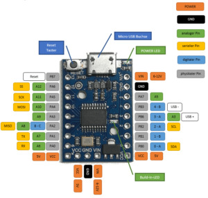
Pinout des Microcontrollers ATtiny167
Aufbau
Bevor ich mit der Entwicklung / Programmierung beginne löte ich zunächst die Pins an den Microcontroller an. Hierzu nutze ich zusätzlich noch 3 Pins um VCC, GND und VIN nach OBEN abzuleiten.
Installation der Treiber
Bevor man mit der Einrichtung in der Arduino IDE beginnen kann, muss man den Treiber installieren. Den aktuellen Treiber findest du unter https://github.com/micronucleus/micronucleus.
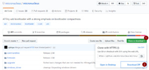
Download des GitHub Repository als ZIP Datei - micronucleus Im Browser findest du rechts die Schaltfläche "Clone or downdload" (1), dort kannst du das komplette Repository als ZIP Datei herunterladen (2). Nachdem die ZIP Datei herunterladen und entpackt wurde. Wird der Ordner "micronucleus-master\windows_driver_installer" geöffnet und die Datei "zadig_2.1.2.exe" mit einem doppelklick geöffnet. In dem neuen Fenster wird nun über das Hauptmenü "Device" > "Load Preset Device" die Konfigurationsdatei für den "digistump Microcontroller" geöffnet und die Schaltfläche "Install Driver betätigt. Wenn der Treiber erfolgreich installiert wurde dann wird dieser im Geräte-Manager von Windows wie folgt angezeigt.
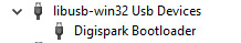
installierter Treiber für den digistump Microcontroller
Einrichten in der Arduino IDE
Nachdem der Treiber erfolgreich installiert wurde muss als nächstes der Treiber für die Arduino IDE installiert werden. Zunächst jedoch muss der Ort der Treiber der Liste der "Liste der zusätzlichen Boardverwalter URLs" hinzugefügt werden. Diese findet man über "Datei" > "Voreinstellungen". Nun muss die Adresse "http://digistump.com/package_digistump_index.json" hinzugefügt werden und es kann dann über den Boardverwalter nach dem Begriff "digistump" (1) gesucht werden. Der erste Eintrag ist hier auch gleich der richtige welchen wir installieren (2) möchten.
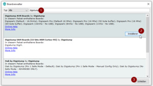
installieren der Treiber für den ATtiny167 über den Boardverwalter der Arduino IDE Wenn der Treiber installiert wurde kann der Dialog über die Schaltfläche "Schließen" (3) wieder verlassen werden. Nun sollte unter den Boards ein weiter Abschnitt erscheinen.
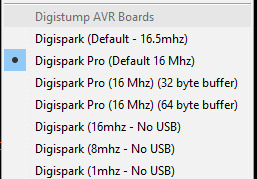
Digistump Boards Für das Board "ATtiny167" wähle ich "Digispark Pro (Default 16 MHz)" aus.
Beispiel
Im ersten kleinen Beispiel werde ich die Build-In-Led zum blinken bringen. Diese kleine SMD LED ist am digitalen Pin 1 angeschlossen. #define buildInLed 1 void setup() { pinMode(buildInLed, OUTPUT); } void loop() { digitalWrite(buildInLed, HIGH); delay(500); digitalWrite(buildInLed, LOW); delay(500); } Für den Upload des Sketches auf den ATtiny167 muss man in der Arduino IDE die Schaltfläche "Hochladen" betätigen, bzw. die Tastenkombination Strg+U. In der Konsole wird dann folgendes Angezeigt: Der Sketch verwendet 4548 Bytes (30%) des Programmspeicherplatzes. Das Maximum sind 14844 Bytes. Globale Variablen verwenden 73 Bytes des dynamischen Speichers. Running Digispark Uploader... Plug in device now... (will timeout in 60 seconds) Nun muss die Taste Reset des ATtiny167 betätigt werden und der Upload beginnt von alleine.

Reset Taster am ATtiny167 Nachdem Upload des Sketches wird in der Konsole der Arduino IDE sehr viel Informationen zum Upload angezeigt. Der Sketch verwendet 912 Bytes (6%) des Programmspeicherplatzes. Das Maximum sind 14844 Bytes. Globale Variablen verwenden 9 Bytes des dynamischen Speichers. Running Digispark Uploader... Plug in device now... (will timeout in 60 seconds) > Please plug in the device ... > Press CTRL+C to terminate the program. > Device is found! connecting: 16% complete connecting: 22% complete connecting: 28% complete connecting: 33% complete > Device has firmware version 2.2 > Device signature: 0x1e9487 > Available space for user applications: 14842 bytes > Suggested sleep time between sending pages: 7ms > Whole page count: 116 page size: 128 > Erase function sleep duration: 812ms parsing: 50% complete > Erasing the memory ... erasing: 55% complete erasing: 60% complete erasing: 65% complete > Starting to upload ... writing: 70% complete writing: 75% complete writing: 80% complete > Starting the user app ... running: 100% complete >> Micronucleus done. Thank you!
Fazit
Der kleine Microcontroller ATtiny167 läßt sich mit etwas vertretbaren Aufwand einrichten und kann danach wie jeder andere Microcontroller aus der Arduino IDE angesprochen und programmiert werden. Read the full article
0 notes
Text
GMH 040 Postbag Soldering Pad, ATTiny167, ATMega32U4, ESP8266, Mega 2650
GMH 040 Postbag Soldering Pad, ATTiny167, ATMega32U4, ESP8266, Mega 2650
The Adafruit package will be opened in another Postbag video.
Soldering Pad Heat-resistant Heat Gun BGA Soldering Station Repair Insulation Insulator Pad Desk Mat Maintenance For Platform $4.54
https://www.aliexpress.com/item/Soldering-Pad-Heat-resistant-Heat-Gun-BGA-Soldering-Station-Repair-Insulation-Insulator-Pad-Desk-Mat-Mainten…
View On WordPress
#ATMega32U4#ATTiny167#Bi-Direction Logic#Dual H-Bridge Motor driver#ESP8266#IIC#Mega 2560#OLED LCD LED#SPI#UART TTL#USB Soldering Iron
0 notes
Text
Recommissioning Katarina Pt1
My Stampede was 6 years old yesterday. It’s been a long while but I’ve been looking at rebooting it for 2017 and beyond. I had FDS do the paintwork and I’ll do the internals. I’ve put in upgraded gears from LZ Mods, a BSUK Stampede upgrade kit, 6kg spring and a 3S LiPo. Well, that’s a bit standard. There are many Stampedes out there with similar or identical builds so I thought I’d go for something different.

Parts for the electronics arrived this morning. Devcon shown for scale (and probably because I’ll need some to mount things with.

The plan is to have a motion sensitive set of lights in the magazine well around the mechanism and at the front where the grilles are. The Stampede has a lovely length to it that makes putting an accelerometer in the forward section worthwhile.
From front to back:


I’m using 8 unit WS2812//WS2811 boards, sold by Adafruit as Neopixels. Essentially, they are a programmable RGB LED capable of ~16million colours driven by a PWM signal. Like most electronics enthusiasts, I’m lazy and use an Arduino and the Adafruit library to drive them rather than running the timing signals myself.
The forward section also contains a GY-61 3-axis accelerometer. This chip uses some serious voodoo silicon to produce 3 outputs (x,y and z) between 0 and 5V depending on the g force on that axis. It has a relative range of -3g through to +3g. That should be more than enough for my needs. The final effect will be a purple colour that goes more red as it moves from side to side and more blue the more up down it goes.
Finally we reach the back and the control board. For this build I’m using an Arduino Nano and its ATMEGA328P 16HZ microprocessor. It’s a touch overkill for this build (I could have used an ATTiny167) but it gives me a bit of head room if I want to do more sophisticated effects in software later. I plan to solder straight to the board with this one. The board is sited at the rear of the blaster for accessibility to its on-board USB port. I might change that if the wiring becomes difficult to route. Ideally, I want to test EMF suppression on long leads with ferrite beads and capacitors for later builds. A Stampede provides a better test-bed for proof of concept before I move over to the radiation hell storm that is a flywheeler.
All parts are linked above and I will be publishing the code and circuit diagrams for this going forward. However, I won’t be unveiling the paintwork until it’s all done. ;)
4 notes
·
View notes
Photo

Serielle Verbindung zwischen einem ATtiny167 und einem Arduino Nano Damit später die Sensorwerte auf dem seriellen Monitor der Arduino IDE ausgegeben werden können muss man sich mit einem zusätzlichen Microcontroller behelfen. #attiny167 #arduino #arduinoproject #arduinonano #serialconnection #maker #electronic #components #diy #tech #techy #technology #DraegerIT (hier: Stefan Draeger Software) https://www.instagram.com/p/B6k4nwVISqE/?igshid=17k17z67qub2b
#attiny167#arduino#arduinoproject#arduinonano#serialconnection#maker#electronic#components#diy#tech#techy#technology#draegerit
0 notes
Photo

Aufbau des Microcontrollers ATtiny167. #attiny167 #microcontroller #electronic #components #diy #tech #techy #technology #DraegerIT (hier: Stefan Draeger Software) https://www.instagram.com/p/B6iMcUxIyt2/?igshid=1oye7h8giehjq
0 notes
Photo

ATtiny167 #attiny167 #microcontroller #electronic #components #diy #tech #techy #technology #DraegerIT (hier: Stefan Draeger Software) https://www.instagram.com/p/B6fSPaSoMi4/?igshid=m1fimj533x2n
0 notes
Photo

Nächstes Projekt für nach die Feiertage. Ein Infrarot Thermometer mit Display. Das Gehäuse kommt selbst erstellt aus dem 3DDrucker. #arduino #arduinoproject #attiny167 #oled #gy906 #infrarotthermometer #maker #electronic #components #diy #tech #techy #technology #DraegerIT (hier: Stefan Draeger Software) https://www.instagram.com/p/B6fQQCZIRp5/?igshid=8zkd9u9x5siv
#arduino#arduinoproject#attiny167#oled#gy906#infrarotthermometer#maker#electronic#components#diy#tech#techy#technology#draegerit
0 notes
Video
instagram
Kapazitiver Touch Sensor am ATtiny167 #attiny167 #led #touchsensor #capacitivetouch #maker #electronic #components #diy #tech #techy #technology #coding #programming (hier: Stefan Draeger Software) https://www.instagram.com/p/B6nTff2IpfK/?igshid=1sntq6tho1z5t
#attiny167#led#touchsensor#capacitivetouch#maker#electronic#components#diy#tech#techy#technology#coding#programming
0 notes
Video
instagram
Serielle Kommunikation zwischen zwei Microcontroller mit Ausgabe von Werten auf dem seriellen Monitor der Arduino IDE. #arduino #arduinoproject #arduinonano #attiny167 #serialconnection #maker #diy #tech #techy #technology #DraegerIT (hier: Stefan Draeger Software) https://www.instagram.com/p/B6k820yo5jA/?igshid=k4iye0eusk17
#arduino#arduinoproject#arduinonano#attiny167#serialconnection#maker#diy#tech#techy#technology#draegerit
0 notes