#ATmega328P
Explore tagged Tumblr posts
Text
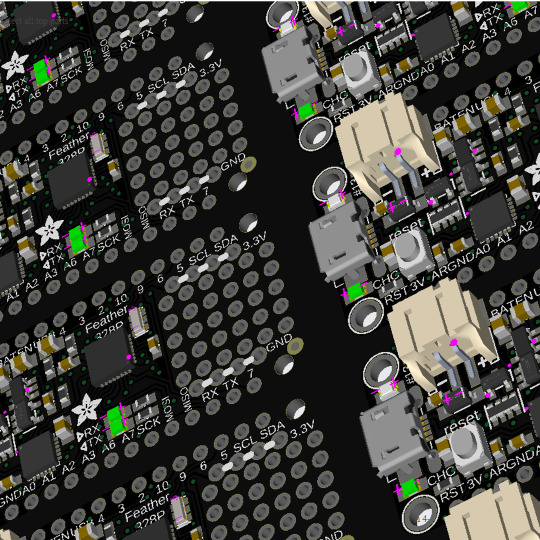
PCB of the day! Adafruit Feather 328P - Atmega328P 3.3V @ 8 MHz 🎛️🪶🔋
Adafruit Feather 328P features an ATmega328P at 3.3V, 8MHz. It’s thin & light with USB-to-Serial, 32K flash, 2K RAM, and battery charging. Compatible with Arduino, it can be paired with various FeatherWings for portable projects.
#adafruit#electronics#pcb#opensource#opensourcehardware#pcboftheday#arduino#feather#microcontroller#portable#batterycharging#usb#atmega328p#developmentboard#flash#ram#arduinochip#featherfamily
3 notes
·
View notes
Text
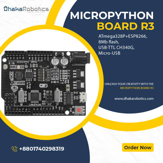
Introducing the MicroPython Board R3 ATmega328P+ESP8266!
Are you ready to take your projects to the next level? Meet the MicroPython Board R3, a powerhouse combining the classic ATmega328P microcontroller with the versatile ESP8266 WiFi chip. Here’s why you’ll love it:
Dual Processors: Enjoy the best of both worlds with the ATmega328P and ESP8266 working together or independently.
8MB Flash Memory: Store more with 8MB of flash memory, perfect for complex projects and data-heavy applications.
USB-TTL CH340G: Seamless USB connectivity with the CH340G converter, making programming and debugging a breeze.
Micro-USB Port: Convenient and modern Micro-USB port for easy power and data transfer.
Versatile Applications: Ideal for IoT projects, home automation, robotics, and more. The possibilities are endless!
Whether you’re a hobbyist or a professional, the MicroPython Board R3 is designed to meet your needs. Get yours today and start creating!
Order Now: https://dhakarobotics.com/.../1039-micropython-board-r3.../
Contact Us: +8801740298319
visit our website: https://dhakarobotics.com/
0 notes
Text
youtube
Micro screws are tiny screws with a diameter typically less than 1.6 millimeters. They are commonly used in electronics, eyeglasses, watches, and other small devices. They are also used in some medical devices.
Micro screws are available in a variety of materials, including steel, brass, and stainless steel. The type of material used will depend on the application. For example, screws used in medical devices will need to be made of a biocompatible material.
There are also a variety of head styles available for micro screws, including Phillips, flat head, and hex head. The head style will be chosen based on the application and the tools that will be used to tighten the screw.
The LGT8F328P is an 8-bit microcontroller manufactured by Logic Green. It's a functional clone of the more popular ATmega328P, commonly used in Arduino Uno, Nano, and Mini boards. This means the LGT8F328P has the same:
Instruction set: Can run the same code written for the ATmega328P. Registers: Same internal memory for storing data during program execution. Pin layout: Can be used on development boards designed for the ATmega328P.
0 notes
Text
Arduino UNO R3 Board ATmega328P DIY Kit | Diykit Solutions
Explore the Arduino UNO R3 Board ATmega328P DIY Kit from Diykit Solutions! Unleash your creativity in electronics and robotics with high-quality materials sourced from trusted suppliers.
Arduino UNO R3 Board ATmega328P DIY Kit
0 notes
Text
Arduino UNO R3 DIP with ATmega328P

Are you looking to buy the Arduino Uno R3 CH340G ATMEGA328P Development Board for your next Arduino project?
Don’t look any further! Ainow, your trusted electronic component supplier in India, offers you this exceptional development board, fully compatible with Arduino Uno R3 projects. In the world of electronics and programming, the Uno R3 CH340G ATMEGA328P Development Board is more than just a microcontroller board; it’s a gateway to endless possibilities.
This board is engineered with precision and durability to meet the needs of both beginners and experienced enthusiasts. Its versatility knows no bounds – whether you’re into robotics, IoT, home automation, or creative automation projects, this board is perfect.
Even new Arduino users will find it easy to use, thanks to the plug-and-play design and user-friendly interface. This development board’s ATmega328P microcontroller and CH340G USB-to-serial converter chip make sure seamless data transfer and efficient performance. You’ll be amazed at how fast your Arduino projects will run with this board.
we believe in offering the best value for your investment. You can buy the Uno R3 CH340G ATMEGA328P Development Board for a competitive price, with no hidden charges. Our nationwide shipping ensures your order reaches you in perfect condition and in the fastest time possible.
We detail Arduino code for making a smart dustbin, the required components, and the circuit diagram for making an automatic dustbin in our blog smart dustbin project using Arduino.
For using this Uno R3 Board compatible with Arduino in your small or DIY projects, you will need some essential components, such as
Breadboard
Wire jumpers
Power supply or batteries
Motors made by BO
Drivers of motor vehicles
The sensors
Check out the Arduino Uno R3 compatible board
1 note
·
View note
Text
Arduino Uno R3 SMD Atmega328P IC

Are you looking for a reliable and feature-rich microcontroller for your electronics projects? The Arduino Uno R3 SMD Atmega328P IC is a top choice for hobbyists, makers, and professionals alike.
The Arduino Uno R3 SMD Atmega328P IC is a compact and lightweight microcontroller that is perfect for portable projects. It features a powerful Atmega328P processor and a range of input and output capabilities, making it a versatile and reliable choice for a wide range of applications.
Some of the key features of the Arduino Uno R3 SMD Atmega328P IC include:
Surface Mount Device (SMD) design: This compact design allows for a smaller and more lightweight microcontroller, making it ideal for portable projects.
Atmega328P processor: The Atmega328P is a high-performance processor with a maximum clock speed of 16 MHz, providing fast and reliable performance.
Wide range of input and output capabilities: The Arduino Uno R3 SMD Atmega328P IC has 14 digital input/output pins, 6 analog inputs, and a number of other features such as a USB connection, a power jack, and an ICSP header.
Extensive support and community: The Arduino platform has a large and active community of developers and users, providing extensive resources and support for projects using the Arduino Uno R3 SMD Atmega328P IC.
Whether you are a beginner or an experienced electronics enthusiast, the Arduino Uno R3 SMD Atmega328P IC is a great choice for your next project. Shop now and start building your masterpiece today!
To code for the Arduino Uno R3 Ch340G USB IC SMD Atmega328P IC, you will need to follow these steps:
Install the Arduino Integrated Development Environment (IDE) on your computer. This is a free software tool that you will use to write and upload code to your Arduino board.
Connect your Arduino board to your computer using a USB cable.
Open the Arduino IDE and select the correct board type and serial port in the "Tools" menu. For the Arduino Uno R3 Ch340G USB IC SMD Atmega328P IC, select "Arduino/Genuino Uno" as the board type and the appropriate serial port for your board.
Write your code in the Arduino IDE. The Arduino programming language is based on C++ and has a number of built-in functions for controlling the board's hardware.
Test your code by using the "Verify" button in the Arduino IDE. This will check your code for any syntax errors.
Upload your code to the Arduino board by clicking the "Upload" button in the Arduino IDE. This will send your code to the board, where it will be executed.
If you encounter any errors or issues while uploading your code, check the Arduino IDE's output window for any error messages. You may also need to troubleshoot your board's connection or other hardware issues.
0 notes
Text
The Arduino Uno R3 is an ATmega328P microcontroller-based development board. This is widely popular in Embedded electronics because of the available resources and easy to use by everybody features. With 14 digital input/output pins where 6 can be configured and used as PWM outputs, 6 as analog inputs is a great addition for I/O related operations. Powered with a 16 MHz ceramic resonator, an USB connection, a power jack, an ICSP header, and a reset button.
2 notes
·
View notes
Text
Arduino-Compatible Boards: Mega 2560 Pro, LilyPad, and Nano
Arduino is a popular open-source hardware and software platform that is widely used for building a variety of electronic projects. The platform has a vast range of boards that are compatible with it, each with different features, capabilities, and price points. In this blog post, we will discuss three of the most popular Arduino-compatible boards: Mega 2560 Pro, LilyPad ATmega328P, and Nano Board R3.
Mega 2560 Pro:
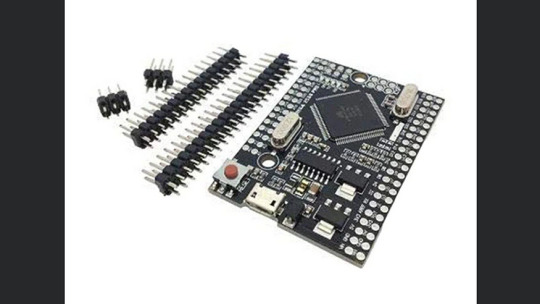
The Mega 2560 Pro is a powerful and versatile board that is designed for advanced projects. It has 54 digital I/O pins, 16 analog inputs, and 4 UARTs (hardware serial ports). It also has a USB host port that can be used to connect USB devices such as keyboards, mice, and game controllers. The board runs on the Atmel ATmega2560 microcontroller, which has a clock speed of 16 MHz. This makes it suitable for running complex programs and driving multiple sensors and actuators simultaneously.
LilyPad ATmega328P:
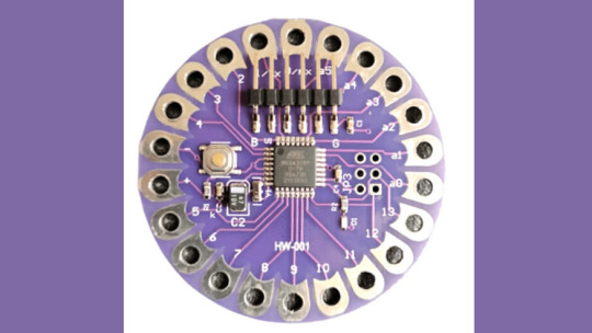
The LilyPad ATmega328P is a wearable board that is designed to be sewn onto clothing and other fabric surfaces. It is based on the Arduino platform and uses the same Atmel ATmega328P microcontroller as the Arduino Uno. The board has 14 digital I/O pins, 6 analog inputs, and can be powered by a 3.7V LiPo battery. It also has a built-in USB port for programming and debugging. The board is compatible with various LilyPad accessories, including sensors, LEDs, and buzzers.
Nano Board R3:

The Nano Board R3 is a compact and affordable board that is ideal for beginners and small projects. It has 22 digital I/O pins, 8 analog inputs, and can be powered via a USB cable or an external power source. The board runs on the Atmel ATmega328 microcontroller, which has a clock speed of 16 MHz. The Nano Board R3 has a built-in USB port for programming and debugging and is compatible with a range of shields and modules that can be used to expand its capabilities.
In conclusion, these three boards offer different features and capabilities, making them suitable for a wide range of applications. The Mega 2560 Pro is ideal for complex projects that require many I/O pins and high processing power. The LilyPad ATmega328P is perfect for wearable projects, while the Nano Board R3 is an excellent choice for beginners and small projects. Regardless of which board you choose, you can be sure that it will be compatible with the vast Arduino community and its extensive library of code and examples.
2 notes
·
View notes
Text
Panduan Lengkap dan Mendalam: Mengenal Arduino Uno dan Manfaatnya
Bagi mereka yang jatuh hati pada teknologi, Arduino Uno bukan sekadar perangkat elektronik, melainkan sebuah jendela ke dunia penuh kemungkinan. Seperti seorang anak kecil yang menemukan mainan ajaib di toko sudut jalan, setiap bagian dari Arduino Uno membuka pintu ke imajinasi, ke inovasi, dan ke semesta kecil yang bisa kita ciptakan sendiri. Dalam tulisan ini, mari kita mengenal lebih dalam apa itu Arduino Uno, sejarahnya, komponennya, hingga bagaimana ia bisa menjadi sahabat terbaik dalam perjalanan Anda di dunia elektronik dan pemrograman.
Apa Itu Arduino Uno?
Arduino Uno adalah salah satu platform mikrokontroler open-source yang paling terkenal. Didesain dengan kesederhanaan dan kemudahan penggunaan, Arduino Uno memungkinkan siapa pun—dari pelajar hingga profesional—untuk merancang, membuat, dan menghidupkan proyek elektronik mereka. Mikrokontroler ini adalah perpaduan sempurna antara perangkat keras dan perangkat lunak yang dirancang agar dapat diprogram untuk menjalankan berbagai fungsi dengan interaksi yang dinamis.
Sejarah Singkat: Dari Italia untuk Dunia
Pada tahun 2005, di sebuah laboratorium kecil di Italia, Massimo Banzi dan timnya memulai perjalanan menciptakan Arduino. Mereka ingin membuat sebuah alat yang dapat digunakan oleh siapa saja tanpa perlu menjadi seorang insinyur elektronik. Sebuah alat yang ramah, sederhana, dan dapat diakses oleh siapa pun. Maka lahirlah Arduino Uno, simbol dari demokratisasi teknologi. Dari proyek kecil ini, lahir sebuah gerakan global yang menghubungkan jutaan orang untuk berbagi ide, proyek, dan inovasi.
Komponen Utama: Jantung dan Nadi Arduino Uno
Arduino Uno, seperti tubuh manusia, memiliki komponen-komponen utama yang menjadi inti dari fungsinya:
Mikrokontroler ATmega328P Mikrokontroler ini adalah "otak" dari Arduino Uno. Ia memiliki memori flash sebesar 32 KB, 2 KB SRAM, dan 1 KB EEPROM. Kombinasi ini memungkinkan mikrokontroler menjalankan berbagai instruksi dengan cepat dan efisien.
Pin Input dan Output Dengan 14 pin digital dan 6 pin analog, Arduino Uno seperti tangan yang bisa menjangkau dunia luar. Pin-pin ini memungkinkan perangkat untuk membaca sinyal dari sensor atau mengirimkan sinyal ke perangkat lain seperti motor atau lampu.
Port Komunikasi Port USB pada Arduino Uno tidak hanya berfungsi untuk menghubungkan perangkat ke komputer, tetapi juga untuk memberikan daya dan memprogramnya. Selain itu, port ICSP memungkinkan pemrograman langsung untuk pengaturan yang lebih kompleks.
Fungsi dan Manfaat: Dari Prototipe Hingga Proyek Besar
Fungsi Arduino Uno:
Prototyping Cepat: Membuat prototipe proyek elektronik menjadi lebih sederhana dan cepat.
Pembelajaran Pemrograman: Platform yang ideal untuk memahami dasar-dasar pemrograman dan elektronik.
Proyek DIY: Membuka jalan bagi penggemar teknologi untuk menciptakan inovasi seperti robot sederhana hingga sistem rumah pintar.
Manfaat Arduino Uno:
Kemudahan Penggunaan: Desainnya yang intuitif membuatnya dapat digunakan bahkan oleh pemula.
Biaya Terjangkau: Cocok untuk pelajar atau penggemar teknologi dengan anggaran terbatas.
Komunitas yang Mendukung: Ribuan forum, tutorial, dan proyek tersedia untuk membantu pengguna di seluruh dunia.
Mengapa Arduino Uno Menonjol?
Arduino Uno memiliki satu kekuatan utama: fleksibilitas. Dengan kompatibilitas terhadap berbagai sensor dan modul seperti modul GPS, sensor suhu, atau modul Bluetooth, Arduino Uno memungkinkan Anda menciptakan apa pun yang Anda bayangkan.
Contoh Proyek: Inspirasi untuk Kreasi
1. Lampu Otomatis
Bayangkan sebuah ruangan yang lampunya menyala saat Anda masuk dan mati ketika Anda pergi. Dengan Arduino Uno, ini bukan lagi impian. Cukup dengan menambahkan sensor gerak atau sensor cahaya, Anda bisa menciptakan sistem seperti ini dengan mudah.
2. Sistem Pengairan Otomatis untuk Tanaman
Bagi para pecinta tanaman, Arduino Uno dapat menjadi asisten andal. Dengan sensor kelembaban tanah, Arduino dapat mengontrol pompa air untuk menyiram tanaman ketika tanah mulai kering.
3. Robot Line Follower
Proyek yang populer di kalangan pemula adalah robot yang dapat mengikuti garis. Dengan kombinasi sensor inframerah dan motor, Arduino Uno menjadi otak di balik robot kecil yang penuh daya tarik ini.
Kesimpulan: Langkah Kecil Menuju Inovasi Besar
Arduino Uno bukan sekadar alat; ia adalah jembatan menuju inovasi. Dengan kombinasi kesederhanaan, keterjangkauan, dan dukungan komunitas yang besar, ia telah mengubah cara dunia melihat teknologi. Setiap proyek kecil yang Anda buat dengan Arduino Uno adalah sebuah langkah menuju sesuatu yang lebih besar. Seperti Andrea Hirata yang menemukan keindahan dalam cerita-cerita sederhana, Arduino Uno membantu kita menemukan keajaiban dalam setiap kode, kabel, dan lampu kecil yang menyala.
Jadi, apa lagi yang Anda tunggu? Dunia penuh ide sedang menanti untuk Anda wujudkan!
Visit us on Telkom University
0 notes
Text
Keyestudio Max Board: Der Arduino-Klon mit dem gewissen Extra

Das Keyestudio Max Board ist schon einige Zeit auf dem Markt erhältlich. In diesem Beitrag möchte ich dir diesen Mikrocontroller vorstellen und zeigen wie du das kleine Spiel "Fang den Regentropfen" auf diesen programmierst. https://youtu.be/P-QlaSB29pI Der Preis mit knapp 25 € für diesen Mikrocontroller hat mich bisher eher abgeschreckt, da dieser zwar ein paar nette Features hat, aber wie ich finde dieses nun nichts Besonderes mehr sind. Auf aliexpress.com habe diesen jetzt für weit unter 20 € gefunden und das hat mich doch verleitet diesen zu kaufen.

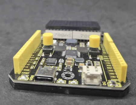


Features des Keyestudio Max Board
Der Mikrocontroller im Format des normalen Arduino UNO R3 verfügt über nachfolgende Features: - USB-Typ-C Buchse, - DC / Batterie Anschluss (PH2.0), - zwei Taster, - zwei RGB LEDs, - drei farbige SMD LEDs (gelb, grün, rot), - einen Piezo Buzzer, - ein Mikrofon, - einen Fotowiderstand - eine 8x16 rote LED Matrix

Pinout des Mikrocontrollers
Die vorhandenen Komponenten auf dem Board schränken jedoch die Verwendung der digitalen Pins ein. Daher werfen wir gleich mal einen Blick auf das Pinout, sodass wir die freien Pins im Blick haben.

KomponentePin8x16 LED MatrixI2C, A4 & A5MikrofonA7FotowiderstandA6Taster RECHTSD2Taster LINKSD3RGB LED LINKSD4RGB LED RECHTSD9SMD LED RotD8SMD LED GrünD10SMD LED GelbD13 Über den 4fach DIP Schalter kann man sich zumindest vier der belegten digitalen Pins wieder "freischalten" und somit wie gewohnt über die Buchsenleisten abgreifen. Pin1D32D43A54A4 Technische Daten des ATmega328P-PU Auf dem Mikrocontroller arbeitet ein ATmega328P-PU welcher nachfolgende technische Daten hat: MikrocontrollerATmega328P-PUTaktgeschwindigkeit16 MHzBetriebsspannung5VEingangsspannung7 bis 12V DCdigitale Pins14, davon 6 als PWManaloge Pins6max. Stromaufnahme an den Pins20 mAmax. Stromaufnahme an 3.3V50 mASpeicher32 kB davon 0,5 kB für den Bootloader reserviert 2 kB SRAM 1 kB EEPROMSchnittstellenUART, I2C, SPIFeaturesLED_BUILTIN an D13
Einrichten des Keyestudio Max Board am PC
Bevor wir mit der Programmierung beginnen können, müssen wir zunächst (soweit noch nicht geschehen) den passenden USB-SERIAL Treiber installieren. Auf dem Board ist ein CP2102 Chip verbaut, in meinem Fall ist dieser nicht installiert (erkennbar am gelben Dreieck im Icon) und ich muss diesen manuell nachinstallieren.


Von der Seite https://www.pololu.com/docs/0J7/all#2 kannst du dir den passenden Treiber als ZIP-Datei für Windows herunterladen.
Programmierung in der Arduino IDE
Die Programmierung erfolgt, wie zu erwarten ist am einfachsten in der Arduino IDE. Auf der offiziellen Seite zu diesem Mikrocontroller beim Hersteller findest du viele Beispiele zu den Features. Nachfolgend möchte ich dir gerne zeigen, wie du das bereits für das Arduino Plug and Make Kit vorgestellte Spiel "Fang den Regentropfen" programmierst. Der Mikrocontroller bringt dazu zwei Taster, die 8x16 LED Matrix sowie den Piezo Buzzer, was dafür optimal ist. (Da alles am Mikrocontroller fest verbaut ist, entfällt hier ein Aufbau der Schaltung, was das ganze nochmal deutlich vereinfacht.) Spiel - "Fang den Regentropfen" am Keyestudio Max BoardHerunterladen Schritt 1 - importieren der benötigten Bibliotheken Zunächst importieren wir die benötigten Bibliotheken. Die Bibliothek für das Ansteuern der LED Matrix bekommen wir vom DropBox Repository von Keyestudio https://fs.keyestudio.com/KS0500 leider musst du dich zuvor dort anmelden, um an diese Ressourcen zu gelangen. Die Bounce2 Bibliothek findest du bequem im internen Bibliotheksverwalter, wenn du nach "Bounce2" suchst. //Einbinden der benötigten Bibliotheken //zum ansteuern der 8x16 LED Matrix #include #include "Keyestudio_LEDBackpack.h" #include "Keyestudio_GFX.h" //zum entprellen der Taster #include Schritt 2 - erzeugen der Objektinstanzen und Felder Für das Spiel benötigen wir einpaar Objektinstanzen wie für die LED Matrix, die Taster etc. Die Koordinaten des Regentropfens sowie der Leiste zum Fangen des selbigen lege ich als globale Variable an, somit muss ich diese nicht durch die Funktionen durchreichen. //Objektinstanz von der Matrix erstellen Keyestudio_8x16matrix matrix = Keyestudio_8x16matrix(); //die beiden Taster sind an //den digitalen Pins D3 & D2 angeschlossen #define buttonLinksPin 3 #define buttonRechtsPin 2 //der Piezo Buzzer ist am digitalen Pin D9 angeschlossen #define buzzer 9 //Objektinstanzen für das entprellen //der Taster mit Bounce erstellen Bounce btnLinks = Bounce(); Bounce btnRechts = Bounce(); //Koordinale für die Leiste zum fangen des Punktes int16_t barXPos = 7; int16_t barYPos = 0; //Koordinate für den Regentropfen int16_t rainDropXPos = 0; int16_t rainDropYPos = 0; //Geschwindigkeit des Spieles //am Anfang legen wir diesen auf 400 fest //dieses repräsentiert einen Wert in Millisekunden long speed = 400; //Zeitpunkt der letzten Ausführung des bewegens eines //Regentropfens auf der LED Matrix long lastAction = -1l; int wonRounds = 0; Schritt 3 - Funktion "setup" Konfigurieren der Matrix, Taster & Buzzer In der Funktion setup starten wir zunächst die Kommunikation mit der LED Matrix und anschließend konfigurieren wir die beiden Taster so das diese über Bounce2 entprellt werden. //beginnen der Kommunikation mit der LED Matrix //via I2C mit der Adresse 0x70 matrix.begin(0x70); //Konfigurieren des entprellens der Taster //verbinden des Pins des Tasters mit dem Objekt btnLinks.attach(buttonLinksPin, INPUT); btnLinks.interval(5); btnRechts.attach(buttonRechtsPin, INPUT); btnRechts.interval(5); //Pin des Piezo Buzzers als Ausgang definieren pinMode(buzzer, OUTPUT); Damit das Spiel gleich startet, setzen wir den Regentropfen an eine Zufällige stelle und zeigen diesen an. //eine Range für die Generierung einer Zufallszahl erstellen randomSeed(analogRead(0)); //setzen der Koordinaten für einen Regentropfen rainDropXPos = 7; rainDropYPos = generateRandomNumber(); //aktualisieren der LED Matrix updateMatrix(); Schritt 4 - Funktion "loop" Auswerten der Taster und Bewegen eines Regentropfens In der Funktion "loop" aktualisieren wir die Taster und werden den jeweiligen Tastendruck aus. //aktualisieren der Button Objekte btnLinks.update(); btnRechts.update(); //Wenn der linke Taster losgelassen wurde, dann... if (btnLinks.rose()) { //die Leiste nach links bewegen moveBar(-1); //aktualisieren der LED Matrix updateMatrix(); } //Wenn der rechte Taster losgelassen wurde, dann... if (btnRechts.rose()) { //die Leiste nach rechts bewegen moveBar(1); //aktualisieren der LED Matrix updateMatrix(); } Am Ende prüfen wir ob die Zeit zwischen den Bewegungen des Regentropfens abgelaufen ist. Würden wir hier mit der Funktion delay arbeiten, so können man wärend der Pause keine der Tasten auswerten. //ermitteln des Zeitpunktes für die nächste Ausführung //der Bewegung des Regentropfens long currentMillis = millis(); if (currentMillis > (lastAction + speed)) { lastAction = currentMillis; moveRainDrop(); updateMatrix(); } Schritt 5 - Funktion "Bewegen der Leiste zum Fangen eines Regentropfens" Wenn eine der beiden Tasten betätigt wurde, dann wird die Funktion moveBar ausgeführt. Zunächst wird ein Ton ausgegeben so das eine akkustische Rückmeldung erfolgt. //Funktion zum bewegen der Leiste zum fangen des Regentropfens //als Parameter wird die Richtung übergeben, //ein Positiver Wert gilt nach rechts und ein negativer nach links void moveBar(int direction) { tone(buzzer, 300, 75); if (direction > 0) { if (barXPos < 15) { barXPos++; } } else { if (barXPos > 0) { barXPos--; } } } Schritt 6 - Funktion "Bewegen eines Regentropfens" Der Regentropfen wird von oben nach unten bewegt wobei unten die Zeile mit dem Index 0 ist und oben 7. Wenn die Zeile des Regentropfens 0 ist dann wird geprüft ob die Leiste sich an der selben Stelle befindet. Wenn diese Runde gewonnen ist dann wird die Geschwindigkeit erhöht und eine neue Runde gestartet und der Wert für wonRounds um eins erhöht. Wenn jedoch die Runde verloren ist, dann werden die gewonnenen Runden angezeigt. //Funktion zum bewegen des Regentropfens UND auswerten //ob die Runde gewonnen oder verloren ist void moveRainDrop() { rainDropXPos--; tone(buzzer, 600, 75); bool startNewGame = false; if (rainDropXPos == 0 && (barXPos == rainDropYPos)) { tone(buzzer, 800, 75); startNewGame = true; speed -= 25; wonRounds++; } else if (rainDropXPos == 0 && (barXPos != rainDropYPos)) { tone(buzzer, 250, 75); startNewGame = true; speed = 400; displayWonRounds(); wonRounds = 0; } if (startNewGame) { rainDropXPos = 7; rainDropYPos = generateRandomNumber(); } }
Schritt 7 - Anzeigen der gewonnenen Runden
Zum schreiben der gewonnenen Runden auf der LED Matrix muss zuvor diese gedreht und der Cursor an eine Position gesetzt werden. Dieses müssen wir jedoch nachdem anzeigen wieder zurücksetzen da dieses globale Einstellungen sind! //Anzeigen der gewonnenen Runden auf der LED Matrix void displayWonRounds() { matrix.setTextSize(1); matrix.setTextWrap(false); matrix.setTextColor(LED_ON); //drehen der Ausrichtung der Matrix matrix.setRotation(1); matrix.clear(); //setzen des Cursors an welchem der Text //geschrieben wird matrix.setCursor(6, 0); matrix.print(String(wonRounds)); matrix.writeDisplay(); delay(1000); //Zurücksetzen des Cursors & der Drehung der Matrix matrix.setCursor(0, 0); matrix.setRotation(0); }
Schritt 8 - Aktualisieren der LED Matrix
Die Funktion zum anzeigen der LED Matrix ist recht easy denn hier müssen wir lediglich nur zwei Punkte anzeigen wo wir die Koordinaten kennen. //Funktion zum zeichnen der Punke auf der LED Matrix void updateMatrix() { matrix.clear(); matrix.drawPixel(barYPos, barXPos, LED_ON); matrix.drawPixel(rainDropXPos, rainDropYPos, LED_ON); matrix.writeDisplay(); } Read the full article
1 note
·
View note
Text
CMPE453 LAB: Basic Color Sensor using Atmega328p Analog to Digital Converter. solved
In this lab, our goal is to design a basic color sensor which is able to distinguish between Red, Yellow and Blue color objects. Items Required: 1. Breadboard 2. Color LEDs (Red, Yellow and Blue) = 03 3. Groove Light Sensor 4. Connecting Wires 5. Arduino Uno Board 6. Groove Base Shield 7. Resistors = 220 ohm x3 (For LEDs). 8. Color Balls (or other similar objects)- Red, Blue and Yellow. Operating…
0 notes
Text
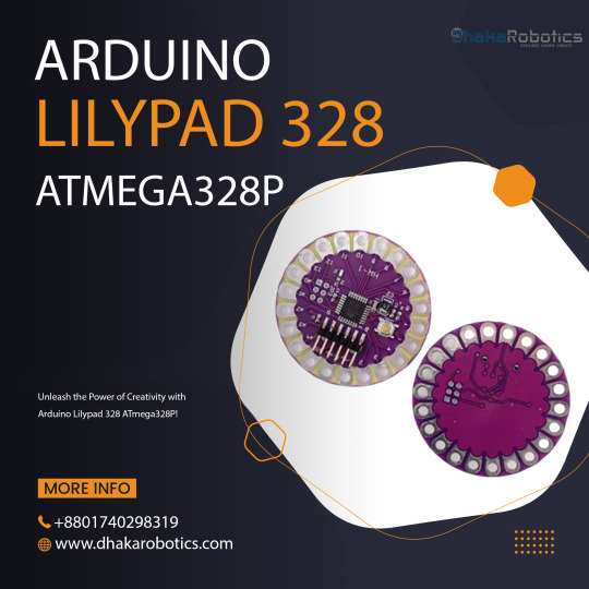
Unleash the Power of Creativity with Arduino Lilypad 328 ATmega328P!
Want to create interactive, tech-infused projects? The Arduino Lilypad 328 ATmega328P is designed specifically for you! Perfect for wearables, e-textiles, and soft circuits, it’s lightweight, flexible, and easy to sew into your designs.
Key Features:
Powered by ATmega328P – Small but mighty!
Lightweight & perfect for wearables
Easy to program for beginners & experts alike
Whether you're adding lights to your clothing or building a unique tech project, Arduino Lilypad is your creative playground!
Start your project today and turn your ideas into reality!
Click here to purchase the product: https://dhakarobotics.com/.../1011-arduino-lilypad-328.../
Contact Us: +8801740298319
visit our website: https://dhakarobotics.com/
0 notes
Text
Arduino Uno
Arduino Uno The Arduino Uno is an open-source microcontroller board based on the Microchip ATmega328P microcontroller (MCU) and developed by Arduino.cc and initially released in 2010. The microcontroller board is equipped with sets of digital and analog input/output (I/O) pins that may be interfaced to various expansion boards (shields) and other circuits. The board has 14 digital I/O pins (six…
0 notes
Text
Unleash Your Creativity with Arduino DIY Kits from Diykit Solutions
Are you ready to dive into the exciting world of electronics and robotics? At Diykit Solutions, we offer a diverse range of DIY kits that empower you to unleash your creativity. Our kits feature high-quality materials sourced from trusted suppliers, ensuring that you can build innovative projects with confidence. Whether you’re a hobbyist, educator, or professional, our Arduino-compatible products will help you turn your ideas into reality.
Explore Arduino-Compatible Sensors and Modules
The world of Arduino opens up a universe of possibilities, especially when you explore the extensive range of Arduino-compatible sensors and modules available at Diykit Solutions. These components are essential for anyone looking to enhance their projects with sensory feedback, interactivity, and automation.
What are Arduino-Compatible Sensors?
Arduino-compatible sensors allow you to collect data from the environment. Whether you’re working on a weather station, a smart home project, or a robotic system, these sensors can help you gather crucial information such as temperature, humidity, light levels, and motion detection. Our collection of sensors is designed to seamlessly integrate with various Arduino boards, making them an ideal choice for your projects.
Enhance Your Projects
By incorporating Arduino-compatible sensors and modules, you can create projects that respond to real-world conditions. For instance, you can use a temperature sensor to trigger an action when the temperature exceeds a certain threshold or a motion sensor to activate lights when someone enters a room. The possibilities are endless!
Build with the Arduino UNO R3 Board ATmega328P DIY Kit
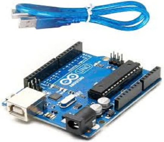
The Arduino UNO R3 Board ATmega328P DIY Kit is a fantastic entry point for anyone interested in electronics and programming. This versatile board is one of the most popular Arduino models and serves as the backbone for countless projects.
Key Features of the Arduino UNO R3
User-Friendly: The Arduino UNO R3 is easy to use, even for beginners. With its straightforward design and compatibility with the Arduino IDE, you can quickly write, upload, and run your programs.
Versatile Connectivity: The board features a variety of input and output pins, allowing you to connect a wide range of sensors, actuators, and other devices.
ATmega328P Microcontroller: The powerful ATmega328P microcontroller ensures that your projects run smoothly and efficiently, enabling complex functionalities without compromising performance.
Ideal for Beginners and Experts
Whether you’re just starting your journey in electronics or looking to create more advanced projects, the Arduino UNO R3 Board ATmega328P DIY Kit has something to offer everyone. With the right resources, you can learn programming, circuit design, and the basics of robotics.
Discover the Arduino-Based Robotics DIY Kit
Robotics is an exciting field that combines engineering, technology, and creativity. With our Arduino-Based Robotics DIY Kit, you can embark on your robotics journey and build your own robots from scratch.

What’s Included in the Kit?
Our robotics kit includes everything you need to create functional robots, including:
Arduino Board: The core of your robot, responsible for processing and controlling its functions.
Motors and Wheels: For movement and mobility, allowing you to create wheeled robots that can navigate their surroundings.
Sensors: To enable your robot to interact with its environment. Use ultrasonic sensors for obstacle avoidance or line-following sensors for navigation.
Learn and Experiment
This kit not only helps you build robots but also teaches you the principles of robotics and programming. By experimenting with different configurations and programming techniques, you can develop your skills and gain a deeper understanding of how robots work.
Explore the Arduino R3 SMD Micro Controller Board Kit
The Arduino R3 SMD Micro Controller Board Kit is another excellent option for those looking to create innovative electronics projects. This compact board offers a range of features that make it suitable for various applications.
Key Benefits of the R3 SMD Board
Compact Size: The SMD (Surface-Mount Device) design allows for a smaller footprint, making it ideal for projects with space constraints.
Integrated Features: This board comes equipped with essential features such as built-in USB connectivity, allowing for easy programming and communication with your computer.
Robust Performance: Designed for reliability and efficiency, the R3 SMD board can handle a variety of tasks, making it suitable for both beginner and advanced projects.
Perfect for Prototyping
Whether you’re prototyping a new idea or creating a final product, the Arduino R3 SMD Micro Controller Board Kit provides the flexibility and functionality you need. Its robust design and compact size make it an excellent choice for any electronics enthusiast.
Why Choose Diykit Solutions?
At Diykit Solutions, we are committed to providing high-quality DIY kits and components that inspire creativity and innovation. Here are some reasons why you should choose us for your Arduino projects:
Diverse Product Range: We offer a wide variety of DIY kits, sensors, and modules to cater to all your electronic and robotic needs.
High-Quality Materials: All our products are sourced from reputable suppliers, ensuring that you receive only the best components for your projects.
Customer Support: Our dedicated team is here to assist you with any questions or concerns you may have. We aim to provide a seamless shopping experience.
Educational Resources: We believe in empowering our customers with knowledge. Our website features tutorials, project ideas, and guides to help you get the most out of your DIY kits.
Start Your Creative Journey Today!
Ready to dive into the world of electronics and robotics? Explore our extensive collection of Arduino-compatible sensors and modules, as well as our Arduino-Based Robotics DIY Kit, Arduino UNO R3 Board ATmega328P DIY Kit, and Arduino R3 SMD Micro Controller Board Kit. At Diykit Solutions, we provide everything you need to unleash your creativity and bring your ideas to life.
Whether you’re a beginner looking to learn or an expert seeking to expand your toolkit, our DIY kits are perfect for anyone passionate about electronics. Don’t wait — start creating innovative projects today!
0 notes
Text
Arduino Nano Board R3 with CH340 chip

Based on the Arduino platform, the Nano R3 Board CH340 Chip without USB Cable does all the functions of the Uno, but has a smaller footprint.
Using Nano CH340 Soldered Board R3 Chip without USB cable is essential for your small project where you don’t need many pins, but the small size is very important to make it look nice.
In comparison to older versions of Arduino Nano with FTDI USB-Serial Chip, the Nano uses a low-cost USB-Serial Chip.
With the ATmega328 (Arduino Nano R3), the Nano is small, complete, and breadboard-friendly. It has more or less the same functionality as the Arduino Uno but in a different package. In addition to lacking a DC power jack, it uses a Mini-B USB cable instead of a standard one.
This device can be powered by a mini-USB cable, a 6-20V unregulated external power supply (pin 30), or a 5V regulated external power supply (pin 27).
Six PWM I/O are included from a total of 14 digital I/O, eight analog inputs, 16Mhz clock speed, and 32kB flash memory.
Please note:
The CH340 chip might not work directly with some PCs/laptops. You will need some drivers for the CH340 chip.
Arduino nano features :
TTL level serial transceiver ports (RX / TX)
Atmel Atmega328P-AU MCU used
It has a bootloader installed
Supports USB download and power supply
Provides support for external DC power supplies of 5V and 12V
2 notes
·
View notes
Text
CMPE453, Section-2 Lab-5 Interrupt Handling using Atmega328p Microcontroller
The purpose of thislab activity isto understand the mechanism of interrupt handling by the microcontroller. Hardware Requirements 1) Arduino Uno Board 2) Breadboard 3) Push Button 4) LED with Resistor (suitable resistance rating) 5) Connecting wires Hardware Setup 1) Assume you have 1 pushbutton (PB1). 2) Connect Push Button with the pin INT0 of microcontroller in such a way that pressing…
0 notes