Don't wanna be here? Send us removal request.
Text
3D Character Modeling & Animation - Day 41
Biblography
Articles
Motherboard. (2015). The New Primary Colors of Science Fiction. [online] Available at: https://motherboard.vice.com/en_us/article/8qx3v4/the-primary-colors-of-science-fiction [Accessed 23 Sep. 2018].
Tofugu.com. (2018). Chibi: The Japanese Word That is Cute and Offensive [online] Available at: https://www.tofugu.com/japanese/chibi/ [Accessed 26 Sep. 2018].
Yesteryeargames.com. (2018). Purpose Of Video Games-Emphasizing The Purpose Behind Video Games. [online] Available at: http://www.yesteryeargames.com/purpose-video-games-emphasizing-purpose.html [Accessed 21 Sep. 2018].
Video
Vimeo. (2014). Animation for Videogames tutorial series 01: Combat Introduction. [online] Available at: https://vimeo.com/97721781 [Accessed 27 Sep. 2018].
YouTube. (2018). Combat Animation for Games. [online] Available at: https://www.youtube.com/watch?v=_16xRLLD3WI [Accessed 27 Sep. 2018].
Website
Dishonored Wiki. (2018). Jessamine Kaldwin. [online] Available at: http://dishonored.wikia.com/wiki/Jessamine_Kaldwin [Accessed 25 Sep. 2018].
Dishonored Wiki. (2018). Treavor Pendleton. [online] Available at: http://dishonored.wikia.com/wiki/Treavor_Pendleton [Accessed 25 Sep. 2018]. Narutopedia. (2018). Amaterasu. [online] Available at: http://naruto.wikia.com/wiki/Amaterasu [Accessed 21 Sep. 2018].
TV Tropes. (2018). Ninja - TV Tropes. [online] Available at: https://tvtropes.org/pmwiki/pmwiki.php/Main/NINJA [Accessed 21 Sep. 2018].
Giant Bomb. (n.d.). Ninja. [online] Available at: https://www.giantbomb.com/ninja/3015-12/ [Accessed 21 Sep. 2018].
0 notes
Text
3D Character Modeling & Animation - Day 40
Reference List
Articles
Halloween Costume Ideas. (2017). The History Behind Ninja Costumes - Halloween Costume Ideas. [online] Available at: https://www.buycostumes.com/ideas/the-history-behind-ninja-costumes/ [Accessed 20 Sep. 2018].
Hunter C. (2018). The 15 Most Stereotypical Characters In Video GamesThunderhawk (Street Fighter). [online] Available at: https://www.complex.com/pop-culture/2012/05/the-15-most-stereotypical-characters-in-video-games/thunderhawk-street-fighter [Accessed 20 Sep. 2018].
Kollar P. (2015). Black developers speak out on stereotypes in gaming. [online] Available at: https://www.polygon.com/2015/3/5/8158645/black-developers-stereotypes-gaming [Accessed 20 Sep. 2018].
Lanka. (2008). The Secrets of Stealth | Way Of Ninja. [online] Available at: https://www.wayofninja.com/the-secrets-of-stealth/#.W6TQ52hKiUk [Accessed 21 Sep. 2018].
Lanka. (2008). Were Shuriken (Ninja Throwing Stars) Used To Kill? | Way Of Ninja. [online] Available at: https://www.wayofninja.com/ninja-throwing-stars-were-used-to-kill/#.W6P192hKiUk [Accessed 20 Sep. 2018].
McLeod, S. (2018). Prejudice and Discrimination in Psychology | Simply Psychology. [online] Simplypsychology.org. Available at: https://www.simplypsychology.org/prejudice.html [Accessed 20 Sep. 2018]. Morgan, T. (2018). 15 Facts Most People Don't Know About The Actual History of Ninjas. [online] Ranker. Available at: https://www.ranker.com/list/history-behind-shinobi-japans-real-ninjas/travis-morgan [Accessed 21 Sep. 2018]. Ravencroft, V. and Ball, M. (2011). A Guide to Science Fiction Subgenres - SciFi Ideas. [online] SciFi Ideas. Available at: http://www.scifiideas.com/writing-2/writing-advice/a-guide-to-science-fiction-subgenres/ [Accessed 23 Sep. 2018].
Takahashi, D. (2012). How Dishonored’s artists created an oppressive, Victorian, steampunk world from scratch. [online] VentureBeat. Available at: https://venturebeat.com/2012/04/26/how-dishonoreds-artists-created-an-oppressive-world-from-scratch/ [Accessed 25 Sep. 2018].
Yesteryeargames.com. (2018). Purpose Of Video Games-Emphasizing The Purpose Behind Video Games. [online] Available at: http://www.yesteryeargames.com/purpose-video-games-emphasizing-purpose.html [Accessed 21 Sep. 2018].
Book
Amazon.co.uk. (2018). [online] Available at: https://www.amazon.co.uk/Science-Handbook-Blackwell-Literature-Handbooks/dp/1405162066 [Accessed 23 Sep. 2018].
Documents
Commons.emich.edu. (2018). [online] Available at: https://commons.emich.edu/cgi/viewcontent.cgi?referer=https://www.google.co.uk/&httpsredir=1&article=1062&context=mcnair [Accessed 20 Sep. 2018].
Haake M & Gulz A. (2018) Visual Stereotypes and Virtual Pedagogical Agents. [online] Available at: https://www.j-ets.net/ETS/journals/11_4/1.pdf [Accessed 20 Sep. 2018].
Models
Drink, F., Design, I., Models, F., Models, 3., Models, M., Models, C., Models, B., Models, L., Models, A., Models, R., Models, O. and Models, F. (2015). sword obj free. [online] Turbosquid.com. Available at: https://www.turbosquid.com/3d-models/sword-obj-free/983256 [Accessed 23 Apr. 2019].
Videos YouTube. (2018). Corvo's Blade Animation - Dishonored. [online] Available at: https://www.youtube.com/watch?v=adKx9f9bRGQ [Accessed 27 Sep. 2018]. YouTube. (2015). Genji Ability Overview | Overwatch. [online] Available at: https://www.youtube.com/watch?v=lYOjIDhJIG0 [Accessed 21 Sep. 2018].
YouTube. (2018). Getting Started with Sculpting - ZBrush for Beginners Tutorial. [online] Available at: https://www.youtube.com/watch?v=_yKGfcp2z3k [Accessed 9 Nov. 2018].
YouTube. (2018). Learn to Sculpt Like a Pro in ZBrush. [online] Available at: https://www.youtube.com/watch?v=0PaYUUvgwYM [Accessed 9 Nov. 2018].
YouTube. (2018). Ninja Gaiden 3 - Gameplay. [online] Available at: https://www.youtube.com/watch?v=C46XPdP0n2w [Accessed 20 Sep. 2018].
YouTube. (2018). Top 5 Sasuke Fights [60FPS]. [online] Available at: https://www.youtube.com/watch?v=Qf-A6WtgJnU [Accessed 21 Sep. 2018].
Websites Pinterest. (2018). Anatomy Reference. [online] Available at: https://www.pinterest.co.uk/connell1494/anatomy-reference/ [Accessed 9 Nov. 2018].
Colour-affects.co.uk. (2018). Psychological Properties Of Colours - Colour Affects. [online] Available at: http://www.colour-affects.co.uk/psychological-properties-of-colours [Accessed 23 Sep. 2018].
Crysis Wiki. (2018). Alcatraz. [online] Available at: http://crysis.wikia.com/wiki/Alcatraz [Accessed 23 Sep. 2018].
Crysis Wiki. (2018). CryNet Nanosuit. [online] Available at: http://crysis.wikia.com/wiki/CryNet_Nanosuit [Accessed 23 Sep. 2018].
Dishonored Wiki. (2018). Corvo Attano. [online] Available at: http://dishonored.wikia.com/wiki/Corvo_Attano [Accessed 25 Sep. 2018].
Elliot, A. (2015). Color and psychological functioning: a review of theoretical and empirical work. Frontiers in Psychology, 6. Katana Mart. (2018). Shinobi Shozoku for sale | Traditional Ninja uniform. [online] Katana Mart. Available at: https://www.katanamart.co.uk/ninjutsugi-aikidogi-karategi-judogi-kendogi-hakama-for-sale/64-shinobi-shozoku-2300100000633.html [Accessed 21 Sep. 2018].
Know Your Meme. (2014). Chibi | Know Your Meme. [online] Available at: https://knowyourmeme.com/memes/subcultures/chibi [Accessed 26 Sep. 2018].
Narutopedia. (2018). Chakra. [online] Available at: http://naruto.wikia.com/wiki/Chakra [Accessed 21 Sep. 2018].
Ninjaencyclopedia.com. (2018). Ninja Sword. [online] Available at: http://www.ninjaencyclopedia.com/weapon/ninjasword.html [Accessed 20 Sep. 2018].
Overwatch Wiki. (2018). Genji. [online] Available at: https://overwatch.gamepedia.com/Genji [Accessed 21 Sep. 2018].
Overwatch, Wiki. (2018). Shimada clan. [online] Overwatch Wiki. Available at: https://overwatch.gamepedia.com/Shimada_clan [Accessed 21 Sep. 2018].
Readwritethink.org. (2018). [online] Available at: http://www.readwritethink.org/files/resources/lesson_images/lesson927/SciFiDefinition.pdf [Accessed 23 Sep. 2018].
ResearchGate. (2018). Visual Stereotypes and Virtual Pedagogical Agents. [online] Available at: https://www.researchgate.net/publication/257869958_Visual_Stereotypes_and_Virtual_Pedagogical_Agents [Accessed 20 Sep. 2018].
Swordsofnorthshire.com. (2018). Ninjato. [online] Available at: https://www.swordsofnorthshire.com/ninja-swords/ninjato [Accessed 27 Sep. 2018].
Thegnomonworkshop.com. (2018). Combat Animation for Games | The Gnomon Workshop. [online] Available at: https://www.thegnomonworkshop.com/tutorials/combat-animation-for-games [Accessed 27 Sep. 2018].
twbsmediaconnell (2015). Assign 1: Genre & subgenres. [online] Slideshare.net. Available at: https://www.slideshare.net/twbsmediaconnell/assign-1-genre-subgenres [Accessed 27 Sep. 2018].
Utopiaanddystopia.com. (2018). Dystopia Definition - Meaning and Concepts of Dystopia. [online] Available at: http://www.utopiaanddystopia.com/dystopia/dystopia-definition/ [Accessed 23 Sep. 2018].
Utopiaanddystopia.com. (2018). Utopia Definition - What is Utopia and What Symbolize?. [online] Available at: http://www.utopiaanddystopia.com/utopia/utopia-definition/ [Accessed 23 Sep. 2018].
0 notes
Text
3D Character Modeling & Animation - Day 39
Appendix A - Figure List
Figure 1: Ryu Hayabusa - Koei Wiki. (2018). Ryu Hayabusa. [online] Available at: http://koei.wikia.com/wiki/Ryu_Hayabusa [Accessed 27 Sep. 2018].
Figure 2: Raiden - Cook. D. (2012). Metal Gear Rising Revengeance - Kojima reveals new Raiden screens - VG247. [online] Available at: https://www.vg247.com/2012/09/10/metal-gear-rising-revengeance-kojima-reveals-new-raiden-screens/ [Accessed 27 Sep. 2018].
Figure 3: Shinobi Shozoku - Katana Mart. (2018). Shinobi Shozoku for sale | Traditional Ninja uniform. [online] Katana Mart. Available at: https://www.katanamart.co.uk/ninjutsugi-aikidogi-karategi-judogi-kendogi-hakama-for-sale/64-shinobi-shozoku-2300100000633.html [Accessed 21 Sep. 2018].
Figure 4: Ninja Gaiden 3 Combat - YouTube. (2018). Ninja Gaiden 3 - Gameplay. [online] Available at: https://www.youtube.com/watch?v=C46XPdP0n2w [Accessed 20 Sep. 2018].
Figure 5: Katana Sword - Horror-shop.com. (2018). [online] Available at: https://www.horror-shop.com/gb/p/katana-samurai-value.html [Accessed 27 Sep. 2018].
Figure 6: Ninjato Sword - Sword, B. (2018). Black Acid Dye 1060 Carbon Steel Ninjato Wakizashi Sword - Katanas For Sale. [online] Katanas For Sale. Available at: https://katanasforsale.com/product/black-acid-dye-1060-carbon-steel-ninjato-wakizashi-sword/ [Accessed 27 Sep. 2018].
Figure 7: Genji Shimada - Overwatch Wiki. (2018). Genji. [online] Available at: http://overwatch.wikia.com/wiki/Genji [Accessed 27 Sep. 2018].
Figure 8: Shurkien - All Ninja Gear. (2018). Titanium Mourning Star Ninja Throwing Shuriken Set. [online] Available at: https://allninjagear.com/titanium-mourning-star-ninja-throwing-shuriken-set [Accessed 27 Sep. 2018].
Figure 9: Genji’s Weapons - I.pinimg.com. (2018). [online] Available at: https://i.pinimg.com/originals/59/91/5b/59915bbd261f9a300a4be4f34b7f6201.png [Accessed 27 Sep. 2018].
Figure 10: Genji Stance (In Game) - YouTube. (2015). Genji Ability Overview | Overwatch. [online] Available at: https://www.youtube.com/watch?v=lYOjIDhJIG0 [Accessed 21 Sep. 2018].
Figure 11: Sasuke Fighting - YouTube. (2018). Top 5 Sasuke Fights [60FPS]. [online] Available at: https://www.youtube.com/watch?v=Qf-A6WtgJnU [Accessed 21 Sep. 2018].
Figure 12: Aragami - Lince Works. (2016). Aragami on Steam. [online] Available at: https://store.steampowered.com/app/280160/Aragami/ [Accessed 27 Sep. 2018].
Figure 13: Steampunk - DeviantArt. (2018). steampunk concept. [online] Available at: https://www.deviantart.com/tyleredlinart/art/steampunk-concept-445066983 [Accessed 27 Sep. 2018].
Figure 14: Utopia - KitBash3d. (2018). Utopia. [online] Available at: https://kitbash3d.com/products/utopia [Accessed 27 Sep. 2018].
Figure 15: Dystopia - Literary Hub. (2018). Dystopia For Sale: How a Commercialized Genre Lost its Teeth. [online] Available at: https://lithub.com/dystopia-for-sale-how-a-commercialized-genre-lost-its-teeth/ [Accessed 27 Sep. 2018].
Figure 16: Crysis 2 Alcatraz - Dartfeld.com. (2012). Crysis 2 Review. [online] Available at: http://www.dartfeld.com/2012/06/crysis-2-review.html#.W60b7WhKiUk [Accessed 27 Sep. 2018].
Figure 17: Treavor Pendleton - Dishonored Wiki. (2018). Treavor Pendleton. [online] Available at: http://dishonored.wikia.com/wiki/Treavor_Pendleton [Accessed 25 Sep. 2018].
Figure 18: Dishonored Corvo Attano - Heroes & Villains Wiki. (2018). Corvo Attano. [online] Available at: http://heroes-villains.wikia.com/wiki/Corvo_Attano [Accessed 27 Sep. 2018].
Figure 19: Corvo Attano Sword - Dishonored Wiki. (2018). Corvo's Blade.jpg. [online] Available at: http://dishonored.wikia.com/wiki/File:Corvo%27s_Blade.jpg [Accessed 27 Sep. 2018].
Figure 20: Chibi Deadpool - DeviantArt. (2018). Chibi Deadpool. [online] Available at: https://www.deviantart.com/iksia/art/Chibi-Deadpool-591783431 [Accessed 27 Sep. 2018].
Character Inspirational Moodboard 1:
Figure 28 - DeviantArt. (2018). Chibi Deadpool. [online] Available at: https://www.deviantart.com/iksia/art/Chibi-Deadpool-591783431 [Accessed 27 Sep. 2018].
Figure 28 - I.pinimg.com. (2018). [online] Available at: https://i.pinimg.com/originals/99/5c/f9/995cf904716737e506fdb577f2a20518.jpg [Accessed 28 Sep. 2018].
Figure 28 - Amazon.com. (2018). [online] Available at: https://www.amazon.com/Star-Wars-Darth-Vader-Deluxe/dp/B00840U88M [Accessed 28 Sep. 2018].
Figure 28 - Katana Mart. (2018). Shinobi Shozoku for sale | Traditional Ninja uniform. [online] Katana Mart. Available at: https://www.katanamart.co.uk/ninjutsugi-aikidogi-karategi-judogi-kendogi-hakama-for-sale/64-shinobi-shozoku-2300100000633.html [Accessed 21 Sep. 2018].
Figure 28 - Black, 9. (2018). 9" Ninja Tactical Fixed Blade Naruto Kunai Karambit Throwing Neck Combat Knife Black. [online] MEGAKNIFE. Available at: https://www.megaknife.com/9-ninja-tactical-fixed-blade-naruto-kunai-karambit-throwing-neck-combat-knife-black/ [Accessed 28 Sep. 2018].
Figure 28 - Sword, B. (2018). Black Acid Dye 1060 Carbon Steel Ninjato Wakizashi Sword - Katanas For Sale. [online] Katanas For Sale. Available at: https://katanasforsale.com/product/black-acid-dye-1060-carbon-steel-ninjato-wakizashi-sword/ [Accessed 27 Sep. 2018].
Character Inspirational Moodboard 2:
Figure 29 - Cook. D. (2012). Metal Gear Rising Revengeance - Kojima reveals new Raiden screens - VG247. [online] Available at: https://www.vg247.com/2012/09/10/metal-gear-rising-revengeance-kojima-reveals-new-raiden-screens/ [Accessed 27 Sep. 2018].
Figure 29 - Koei Wiki. (2018). Ryu Hayabusa. [online] Available at: http://koei.wikia.com/wiki/Ryu_Hayabusa [Accessed 27 Sep. 2018].
Figure 29 - Abed. A. (2018). NINJA ASSASSIN 3016, ALI ABED. [online] Available at: https://www.artstation.com/artwork/4kqk1 [Accessed 28 Sep. 2018].
Figure 29 - Abed. A. (2018). NINJA ASSASSIN 3016, ALI ABED. [online] Available at: https://www.artstation.com/artwork/4kqk1 [Accessed 28 Sep. 2018].
Figure 29 - Pinterest. (2018). futuristic ninja - Google Search | Reference | Pinterest | Futuristic, Ninja armor and Sci fi. [online] Available at: https://www.pinterest.co.uk/pin/521502831826581961/?lp=true [Accessed 28 Sep. 2018].
Character Inspirational Moodboard 3:
Figure 30 - Abed. A. (2018). NINJA ASSASSIN 3016, ALI ABED. [online] Available at: https://www.artstation.com/artwork/4kqk1 [Accessed 28 Sep. 2018].
Figure 30 - Germain. V. (2018). Sci-fi Soldier2, Val Germain. [online] Available at: https://www.artstation.com/artwork/DNw6A [Accessed 28 Sep. 2018].
Figure 30 - Benton. D. (2018). Hi-Tech Male Soldiers , Darren Benton. [online] Available at: https://www.artstation.com/artwork/QKWe4 [Accessed 28 Sep. 2018].
Appendix B - Primary Images
Figure 21: ArtStation Collection
Figure 22: Research Image
Figure 23: Character Blockout Reference Editing 1
Figure 24: Character Blockout Reference Editing 2
Figure 25: Character Blockout Reference Editing 3
Figure 26: Character Bio Sheet 1
Figure 27: Character Bio Sheet 2
Figure 31: Character Base Mesh Creation Practice 1
Figure 32: Character Base Mesh Creation Practice 2
Figure 33: Character Channel Box Measurements
Figure 34: Character Base Mesh Creation Practice 3
Figure 35: Character Base Mesh Creation Practice 4
Figure 36: Character Base Mesh Creation Practice 5
Figure 37: Character Base Mesh Creation Practice 6
Figure 38: Character Base Mesh Creation Practice 7
Figure 39: Character Hand Creation Practice 1
Figure 40: Character Hand Creation Practice 2
Figure 41: Character Hand Creation Practice 3
Figure 42: Character Hand Creation Practice 4
Figure 43: Character Hand Creation Practice 5
Figure 44: Character Hand Creation Practice 6
Figure 45: Character Hand Creation Practice 7
Figure 46: Character Hand Creation Practice 8
Figure 47: Helmet Concept Image 1
Figure 48: Helmet Concept Image 2
Figure 49: Character Hand Creation Practice 9
Figure 50: Character Hand Creation Practice 10
Figure 51: Character Hand Creation Practice 11
Figure 52: Character Hand Creation Practice 12
Figure 53: Character Base Mesh Creation Practice 8
Figure 54: Character Base Mesh Creation Practice 9
Figure 55: Character Base Mesh Creation Practice 10
Figure 56: Character Base Mesh Creation Practice 11
Figure 57: Character Base Mesh Creation Practice 12
Figure 58: Character Base Mesh Creation Practice 13
Figure 59: Character Feet Creation Practice
Figure 60: Character Head Creation Practice 1
Figure 61: Character Head Creation Practice 2
Figure 62: Character Head Creation Practice 3
Figure 63: Character Head Creation Practice 4
Figure 64: Character Head Creation Practice 5
Figure 65: Helmet Concept Image 3
Figure 66: Head Detail/Topology Practice 1
Figure 67: Head Detail/Topology Practice 2
Figure 68: Head Detail/Topology Practice 3
Figure 69: Head Detail/Topology Practice 4
Figure 70: Head Detail/Topology Practice 5
Figure 71: Head Detail/Topology Practice 6
Figure 72: Head Detail/Topology Practice 7
Figure 73: Head Detail/Topology Practice 8
Figure 74: Head Detail/Topology Practice 9
Figure 75: Head Detail/Topology Practice 10
Figure 76: Head Detail/Topology Practice 11
Figure 77: Head Detail/Topology Practice 12
Figure 78: Head Detail/Topology Practice 13
Figure 79: Head Detail/Topology Practice 14
Figure 80: Head Detail/Topology Practice 15
Figure 81: Head Detail/Topology Practice 16
Figure 82: Head Detail/Topology Practice 17
Figure 83: Head Detail/Topology Practice 18
Figure 84: Head Detail/Topology Practice 19
Figure 85: Head Detail/Topology Practice 20
Figure 86: 3D Coat Practice 1
Figure 87: Initial Armour Concepts 1
Figure 88: Initial Armour Concepts 2
Figure 89: Initial Armour Concepts 3
Figure 90: Initial Armour Concepts 4
Figure 91: Final Character Concepts 1
Figure 92: Final Character Concepts 2
Figure 93: Character Colour Variation
Figure 94: Character Zbrush Sculpting 1
Figure 95: Character Zbrush Sculpting 2
Figure 96: Character Zbrush Sculpting 3
Figure 97: Character Zbrush Sculpting 4
Figure 98: Character Zbrush Sculpting 5
Figure 99: Character Zbrush Sculpting 6
Figure 100: Character Zbrush Sculpting 7
Figure 101: Character Zbrush Sculpting 8
Figure 102: Character Zbrush Sculpting 9
Figure 103: Character Zbrush Sculpting 10
Figure 104: Character Zbrush Sculpting 11
Figure 105: 3D Coat Tool Practice 1
Figure 106: 3D Coat Tool Practice 2
Figure 107: 3D Coat Tool Practice 3
Figure 108: 3D Coat Tool Practice 4
Figure 109: 3D Coat Tool Practice 5
Figure 110: Character Zbrush Sculpting 12
Figure 111: Character Zbrush Sculpting 13
Figure 112: Character Zbrush Sculpting 14
Figure 113: 3D Coat Character Setup 1
Figure 114: 3D Coat Character Setup 2
Figure 115: Character Zbrush Sculpting 15
Figure 116: Character Zbrush Sculpting 16
Figure 117: Character Zbrush Sculpting 17
Figure 118: Character Zbrush Sculpting 18
Figure 119: Character Zbrush Sculpting 19
Figure 120: Character Zbrush Sculpting 20
Figure 121: Character Zbrush Sculpting 21
Figure 122: Character Zbrush Sculpting 22
Figure 123: Character Zbrush Sculpting 23
Figure 124: Character Zbrush Sculpting 24
Figure 125: Character Zbrush Sculpting 25
Figure 126: Character Zbrush Sculpting 26
Figure 127: 3D Coat Retopology Practice 1
Figure 128: 3D Coat Retopology Practice 2
Figure 129: 3D Coat Retopology Practice 3
Figure 130: 3D Coat Retopology Practice 4
Figure 131: 3D Coat Retopology Practice 5
Figure 132: 3D Coat Retopology Practice 6
Figure 133: Character 3D Coat Sculpting 1
Figure 134: Character 3D Coat Sculpting 2
Figure 135: Character 3D Coat Sculpting 3
Figure 136: Character 3D Coat Sculpting 4
Figure 137: Character 3D Coat Sculpting 5
Figure 138: Character 3D Coat Sculpting 6
Figure 139: Character 3D Coat Sculpting 7
Figure 140: Character 3D Coat Sculpting 8
Figure 141: Character 3D Coat Sculpting 9
Figure 142: Character 3D Coat Sculpting 10
Figure 143: Character 3D Coat Sculpting 11
Figure 144: Character 3D Coat Sculpting 12
Figure 145: Character 3D Coat Sculpting 13
Figure 146: Character 3D Coat Sculpting 14
Figure 147: Character 3D Coat Sculpting 15
Figure 149: Character 3D Coat Sculpting 16
Figure 150: Character 3D Coat Sculpting 17
Figure 151: Character 3D Coat Sculpting 18
Figure 152: Character 3D Coat Sculpting 19
Figure 153: Character UV Practice 1
Figure 154: Character UV Practice 2
Figure 155: Character UV Practice 3
Figure 156: Character UV Practice 4
Figure 157: Character UV Practice 5
Figure 158: Character 3D Coat Sculpting 20
Figure 159: Character 3D Coat Sculpting 21
Figure 160: Character 3D Coat Sculpting 22
Figure 161: Character 3D Coat Sculpting 23
Figure 162: Character 3D Coat Sculpting 24
Figure 163: Character 3D Coat Sculpting 25
Figure 164: Character 3D Coat Sculpting 26
Figure 165: Character 3D Coat Sculpting 27
Figure 166: Character 3D Coat Sculpting 28
Figure 167: Character 3D Coat Sculpting 29
Figure 168: Character Retopology 1
Figure 169: Character Retopology 2
Figure 170: Character Retopology 3
Figure 171: Character Retopology 4
Figure 172: Character Retopology 5
Figure 173: Character Retopology 6
Figure 174: Character Retopology 7
Figure 175: Character Retopology 8
Figure 176: Character Retopology 9
Figure 177: Character Retopology 10
Figure 178: Character Retopology 11
Figure 179: Character Retopology 12
Figure 180: Character Retopology 13
Figure 181: Character Retopology 14
Figure 182: Character Retopology 15
Figure 183: Character Retopology 16
Figure 184: Character Retopology 17
Figure 185: Character Retopology 18
Figure 186: Character Retopology 19
Figure 187: Character Retopology 20
Figure 188: Character Retopology 21
Figure 189: Character Retopology 22
Figure 190: Character Retopology 23
Figure 191: Character Retopology 24
Figure 192: Character Retopology 25
Figure 193: Character Retopology 26
Figure 194: Character Retopology 27
Figure 195: Character Retopology 28
Figure 196: Character Retopology 29
Figure 197: Character Retopology 30
Figure 198: Character Retopology 31
Figure 199: Character Retopology 32
Figure 200: Character Retopology 33
Figure 201: Character Retopology 34
Figure 202: Character Retopology 35
Figure 203: Character Retopology 36
Figure 204: Character Accessory Creation 1
Figure 205: Character Accessory Creation 2
Figure 206: Character Accessory Creation 3
Figure 207: Character Accessory Creation 4
Figure 208: Character Accessory Creation 5
Figure 209: Character Accessory Creation 6
Figure 210: Character Accessory Creation 7
Figure 211: Character Accessory Creation 8
Figure 212: Character Accessory Creation 9
Figure 213: Character Accessory Creation 10
Figure 214: Character Accessory Creation 11
Figure 215: Character Accessory Creation 12
Figure 216: Character Accessory Creation 13
Figure 217: Character Accessory Creation 14
Figure 218: Character Unwrapping 1
Figure 219: Character Unwrapping 2
Figure 220: Character Unwrapping 3
Figure 221: Character Unwrapping 4
Figure 222: Character Unwrapping 5
Figure 223: Character Unwrapping 6
Figure 224: Character Texturing 1
Figure 225: Character Texturing 2
Figure 226: Character Texturing 3
Figure 227: Character Texturing 4
Figure 228: Character Texturing 5
Figure 229: Character Texturing 6
Figure 230: Character Texturing 7
Figure 231: Character Texturing 8
Figure 232: Character Texturing 9
Figure 233: Character Texturing 10
Figure 234: Character Texturing 11
Figure 235: Character Texturing 12
Figure 236: Character Texturing 13
Figure 237: Character Texturing 14
Figure 238: Character Texturing 15
Figure 239: Character Texturing 16
Figure 240: Character Texturing 17
Figure 241: Character Texturing 18
Figure 242: Character Texturing 19
Figure 243: Character Texturing 20
Figure 244: Character Texturing 21
Figure 245: Character Texturing 22
Figure 246: Character Texturing 23
Figure 247: Character Texturing 24
Figure 248: Character Texturing 25
Figure 249: Character Texturing 26
Figure 250: Character Texturing 27
Figure 251: Character Final Render
Figure 252: Animation Practice 1
Figure 253: Animation Practice 2
Figure 254: Rig Creation 1
Figure 255: Rig Creation 2
Figure 256: Rig Creation 3
Figure 257: Rig Creation 4
Figure 258: Rig Creation 5
Figure 259: Rig Creation 6
Figure 260: Rig Creation 7
Figure 261: Rig Creation 8
Figure 262: Rig Creation 9
Figure 263: Rig Creation 10
Figure 264: Rig Creation 11
Figure 265: Rig Creation 12
Figure 266: Rig Creation 13
Figure 267: Rig Creation 14
Figure 268: Rig Creation 15
Figure 269: Rig Creation 16
Figure 270: Rig Creation 17
Figure 271: Rig Creation 18
Figure 272: Rig Creation 19
Figure 273: Rig Creation 20
Figure 274: Rig Creation 21
Figure 275: Rig Creation 22
Figure 276: Rig Creation 23
Figure 277: Rig Creation 24
Figure 278: Rig Creation 25
Figure 279: Rig Creation 26
Figure 280: Rig Creation 27
Figure 281: Rig Creation 28
Figure 282: Rig Creation 29
Figure 283: Walk Cycle Reference 1
Figure 284: Animation Practice 3
Figure 285: Walk Cycle Reference 2
Figure 286: Animation Practice 4
Figure 287: Animation Practice 5
Figure 288: Animation Practice 6
Figure 289: Animation Practice 7
Figure 290: Animation Practice 8
Figure 291: Graph Editor
Figure 292: Initial Storyboard
Figure 293: Rig Creation 30
Figure 294: Rig Creation 31
Figure 295: Rig Creation 32
Figure 296: Rig Creation 33
Figure 297: Rig Creation 34
Figure 298: Rig Creation 35
Figure 299: Rig Creation 36
Figure 300: Rig Creation 37
Figure 301: Rig Creation 38
Figure 302: Rig Creation 39
Figure 303: Rig Creation 40
Figure 304: Rig Creation 41
Figure 305: Rig Creation 42
Figure 306: Rig Creation 43
Figure 307: Final Animation Storyboard
Figure 308: Skinning 1
Figure 309: Skinning 2
Figure 310: Skinning 3
Figure 311: Skinning 4
Figure 312: Skinning 5
Figure 313: Skinning 6
Figure 314: Skinning 7
Figure 315: Skinning 8
Figure 316: Skinning 9
Figure 317: Skinning 10
Figure 318: Skinning 11
Figure 319: Skinning 12
Figure 320: Skinning 13
Figure 321: Skinning 14
Figure 322: Skinning 15
Figure 323: Skinning 16
Figure 324: Skinning 17
Figure 325: Skinning 18
Figure 326: Skinning 19
Figure 327: Skinning 20
Figure 328: Skinning 21
Figure 329: Animation Production 1
Figure 330: Animation Production 2
Figure 331: Animation Production 3
Figure 332: Animation Production 4
Figure 333: Animation Production 5
Figure 334: Animation Production 6
Figure 335: Animation Production 7
Figure 336: Animation Production 8
Figure 337: Animation Production 9
Figure 338: Animation Production 10
Figure 339: Animation Production 11
Figure 340: Animation Production 12
Figure 341: Animation Production 13
Figure 342: Animation Production 14
Figure 343: Animation Production 15
Figure 344: Animation Production 16
Figure 345: Animation Production 17
Figure 346: Animation Production 18
Figure 347: Key Light
Figure 348: Fill Light
Figure 349: Back Light
Figure 350: Combined Lighting
Figure 351: Render Settings 1
Figure 352: Render Settings 2
0 notes
Text
3D Character Modeling & Animation - Day 38
Throughout the production process of the 3D Character Modeling & Animation module there have been many lessons that I have learnt about the overall production process of generating a game ready video game character from scratch, with no prior experience. In addition to how to effectively generate a rig for the character that will allow for the production of an animation aimed at demonstrating personality. Due to the variety of tasks and stages within the production process of this module, many positive and negative aspects occurred, however, in this case the aspects were mostly positive.
The main reason for the overall production process being positive is due to how much I learned along the way, I have explored skills that I have had no prior experience with whilst also enhancing other skills that needed more work. With being tasked to create a character, I needed to explore new software and new ways of modeling, software such as Zbrush and 3D Coat were used to sculpt the character from scratch. However, with this there were also a lot of unfortunate circumstances that occurred primarily throughout the first half of the production process. During the first semester of this year the focus was on designing, creating and texturing the character, however, during this process I fell behind resulting in me having to catch up over the Christmas holiday. The reason I fell behind on this module during the first semester could be a combination of ambition and poor time management in relation to the other projects I was working on, during the first semester I was under some stress due to another project that was not going so well, trying to manage that project alongside learning and developing new skills with character creation resulted in my time management during that semester being poor, however, I was able to catch up and in doing this manage my time more effectively during the second semester to not end up in the same situation.
Within the second semester I was able to effectively produce my rig and animation to a good standard, I believe the reason for this is due to learning to tame my ambition and attempt to generate a realistic product within the time-frame that I have been given, with this I was able to balance between the two projects.
Even though character creation is not the specific field that I am aiming for I am happy that I was able to learn the skills required to generate a game character as it give me a better understanding as to the ways in which they are created, whilst also introducing me to new software that can be used to improve other aspects of 3D art such as with props, sculpting details and engravings into objects can be useful in some circumstances. Continuing to experiment with these software will overall benefit other projects that I end up creating.
To conclude I believe that I have produced a well rounded character, rig and animation, learning a wide array of skills that have expanded my 3D arsenal. I plan to take the skills that I have learned during the production process and apply them in different ways within future projects.
0 notes
Text
3D Character Modeling & Animation - Day 37
With the changes made to the animation I rendered the animation again, compiling it in Premiere Pro. I then uploaded the animation to Vimeo, here is the link to the animation:
https://vimeo.com/330211554
In addition I also uploaded to final, textured renders of the character to Artstation. Link:
https://www.artstation.com/artwork/oO0Omk
0 notes
Text
3D Character Modeling & Animation - Day 36
After receiving the list of changes that I needed to make for the animation I tried my best to implement as many of them as possible. Unfortunately, I could not implement all of the changes recommended. One change I could not make due to conflicting elements within the animation, resulting in additions or changes generating a strange effect with overlapping animation between two still poses even if there is no animation present.
The first change that I made within the animation was to add a slight bounce to the character as he makes contact with the ground when sitting down, this was done through adjusting the root control translation value. Initially when applying this effect I had the character move up upon making contact with the ground, for some reason this looked wrong and I could not figure out why, resulting in me making tweaks to the animation to try and make it appear natural, however, after thinking about it for a while I realised that the effect gravity would have would result in the impact pushing them down before being bounced up, therefore, I added this extra frame before the character moves up resulting in a realistic movement. The purpose of this addition is to make the sitting animation appear less static and overall more realistic.
The next adjustment that I needed to make was with the first camera, near the start of the animation, the camera pans up the character and then pulls back to provide a full view of the character, I needed to adjust the speed in which the camera pulls back making it slower. To do this I increased the gap between the frames naturally increasing the length of time the animation takes. However, this change influences the timing of the rest of the animation, with the camera now being slower, the animation of the character now starts earlier, therefore, I had to adjust the timing of the whole animation overall increasing its length by a small amount to create the same timing between the frames.
The third and final change that I was able to make was adjusting the movement when the character pulls back before driving the sword into the ground, as the character assumes the position he adjusts the position of his feet, however, the feet slide into the new position which is not a natural movement, therefore, I needed the character to raise his foot and step into the pose as opposed to slide, making this adjustment was relatively simple only requiring one in between frame of the foot up in the air. With this I also made adjustments to his left leg, before the changes the left leg would also slide across the ground slightly, but after testing the transition between the poses in real life I realised that the left leg does not need to move and can stay stationary, so I made the change to keep the foot in the same position.
The final change that I needed to make, but unfortunately could not, was an adjustment to the impact of the sword, my tutor recommended applying a delay within the animation as the character steps in holding that pose for a second, then continuing the animation as normal, in theory this proceed sound relatively simple, however, any change that I made to the animation itself or the timing of the animation would result in adverse effects that would resulting in the animation not working as intended, with certain areas being delayed or the animation of that area changing. If the frames of the animation were duplicated to hold that same pose for a certain length of time, some animation would override the pose cause certain areas of the character to still move. Due to this I could not effectively implement this change.
0 notes
Text
3D Character Modeling & Animation - Day 35
Finally it was time to render the animation through using the built in rendering system within Maya. In normal circumstances I would use batch render to render each frame of the animation out as individual .jpeg images, however, I was informed that this method does not work with the newly introduced renderer called Arnold. Therefore, instead of using batch render we use render sequence, this option is very similar to batch render and is also situated within the same tab. therefore, it is easy to find. However, before the rendering process can begin some setting need to be adjusted to configure it correctly, the main settings being adjusted are the rendering resolution and the file format that they will be exported as, by default Maya sets the renders to a low resolution, potentially to make it easier to render on lower end machines, however, I need the resolution to be higher, this is done through the render settings window, that can be accessed via the windows tab and hovering over rendering editors. Immediately upon accessing the window the file format option will be visible, I changed this to the .jpeg file format so that I could both see if the render was correct and also compile all of the images together in an editing software to form the animation. after adjusting the file format I also adjusted frame/animation ext, this determines how each frame will be names and numbered when it is exported, this needs to be adjusted in order to gain access to the ability to adjust the start and end frame, allowing for the rendering process to be fine tuned to specific frames, personally I need this in order to swap between the cameras at certain points, therefore, only a portion of the animation needs to be rendered.
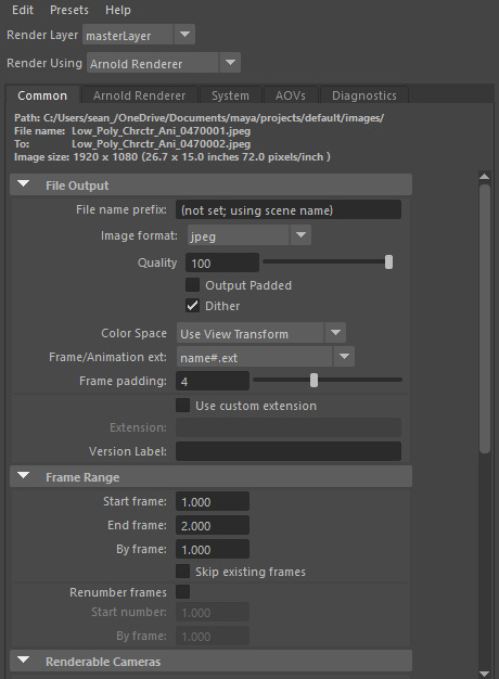
Figure 351: Render Settings 1
Then through scrolling down in the window both the renderable camera and rendering resolution can be changed, when referring to my animation I only have two cameras that need to switch halfway through the animation, therefore, I will make use of the ability to change the rendering camera in combination with setting the start and end frame. I then changed the resolution to 1920 by 1080 also known as 1080p to get a high quality animation.
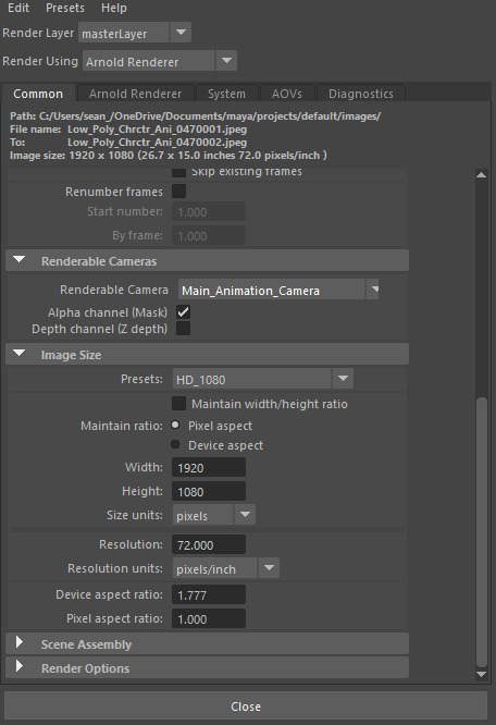
Figure 352: Render Settings 2
With this I then proceeded to render my animation, luckily due to the power of the processor within my computer it was complete within a couple of hours, allowing me to compile the images together into an animation using Premiere Pro, the way this is done is through importing the first image of the animation as an image sequence, this option is visible when importing, this will select all of the images within the file and combine them together as a video clip, with this I then saved and exported the video from Premiere and sent it to my tutor to gather his opinion on anything that her believe needs addressing. Both fortunately and unfortunately he came back with a list of a couple of adjustments that I could make to my animation to make it that much better then it is currently, however this does mean I will have to make the changes and re-render my animation.
0 notes
Text
3D Character Modeling & Animation - Day 34
During this weeks session’s of working on the Character Modeling & Animation module I have tackled a number of different areas, mainly in relation to the portfolio and animation. During the first session of the week I focused solely on the portfolio, attempting to get up to date on the figure list, as I had fell very far behind since starting the new semester. Due to this, adjusting the figure list took most of the day leaving little room to finalise the animation, however, this was also not possible due to our tutor being absent for the day, making it the optimal time to work on the figure list for the portfolio. The process of updating the figure list was a tedious one consisting of a large amount of copy and pasting between the figure list document and portfolio. I still have quite a long way to go in updating this figure list as I have only managed to reach up until blog post number 20.
Within the second session of the week I have managed to finalise the animation, through making some slight tweaks and adjustments to a singular frame causing the foot to slide ever so slightly on impact with the ground. In order to fix this issue, I adjusted the inbetween frame allowing for a small transition period in the animation of the foot, reducing the effect of the slide.
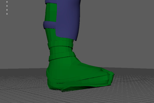
Figure 345: Animation Production 17
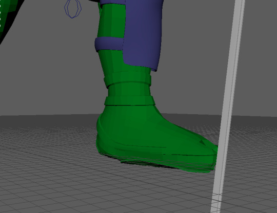
Figure 346: Animation Production 18
With this change the animation was complete, leaving me to producing the lighting for the scene. The process of lighting the scene has produced some issues as personally I do not have a lot of experience with lighting scenes and the overall process that go into producing realistic and effective lighting, therefore, I consulted my tutor on a base idea that I could work off of, he recommended the three point lighting technique. Three point lighting consists of three different light sources positioned around the character in different positions, the first light called the “keylight” is a directional light that is positioned at an off angle in front of the character, this acts as the main light that will cast shadows. the colour of this light often determines the overall colour of the other two lights, for my personal scene I wanted a darker tone with the lighting to reflect the overall animation that I have produced, therefore, through adjusting the temperature of the light within the settings I made it more of a blue colour.
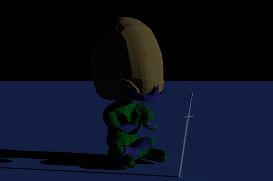
Figure 347: Key Light
The second light is a point light again positioned at an off angle in front of the character however this one is on the opposite side when compared to the directional light. The point light tends to have lower intensity and also different colour when compared to that of the directional light. The purpose of the point light is fill in the area that is not covered by the keylight whilst adding a slight accent of colour by changing the colour of the light to the opposite of the keylight, I again did this using the temperature.
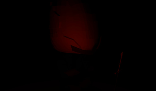
Figure 348: Fill Light
The third light is a spot light positioned behind the character in relation to the camera. The purpose of this light is to be very bright and create an outline type effect around the character adding to the overall lighting. Creating this light came with some difficulties as in attempting to create the effect the combination of the high intensity and exposure of the light caused a grain effect around a lot of the object, even areas that were not effect by the light, therefore, a balance between the exposure and intensity needed to be found in order to create a good effect. Due to using two cameras within the animation in order to acquire two different angles the position of the back light will need to change depending on the camera when it comes to rendering the animation, at first I thought this was a bad idea due to the light casting onto the floor, however, my tutor showed me a way of removing this effect making the light only affect the character, making it a very viable option.
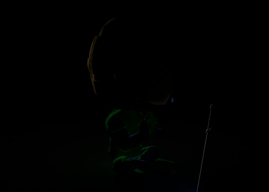
Figure 349: Back Light
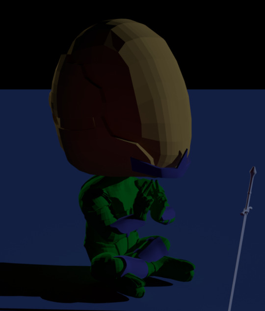
Figure 350: Combined Lighting
After applying the light I received another recommendation in order to emphasise the style, this recommendation was to add a ground plane applying a texture that is a similar colour to that of the keylight in order to emphasise the mood and tone of the scene/animation, therefore, this is what I did, it was also recommended that I generated a background colour, however, when applying this colour it would not display within the render, therefore, I decided to leave it black. Personally I like the background colour being black as I believe it adds to the tone that has been set.
0 notes
Text
3D Character Modeling & Animation - Day 33
Since the previous blog post I have continued with the animation process, focusing on creating the key frames of the main poses within the animation. The main focus this week was to make the character sit down and start meditating, due to the sit being a more complicated motion to animate I decided to gather reference of myself performing the action in order to break down the main key frames featured within. Once this video was recorded I then took it into the software Kinovea to allow myself the run through the video frame by frame, gathering the relevant key frames and saving them, therefore, allowing me to see what the frames are required for the motion. With this I simply went through copying each keyframe, whilst making slight manual adjustments in order to fit the animation to the type of character that I have created. Within my initial attempts the create this section of the animation I made some mistakes with certain elements, such as the position of the root control in relation to the character, as when one leg is the main support for the body the hips will move in favour of that leg in order to provide balance, I did not take this into account throughout the whole animation, therefore, I decided to make these adjustments after applying this to when the character sits down.
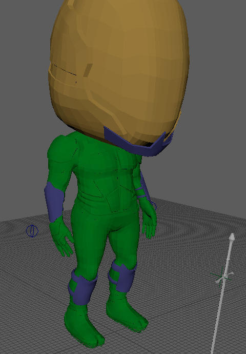
Figure 333: Animation Production 5
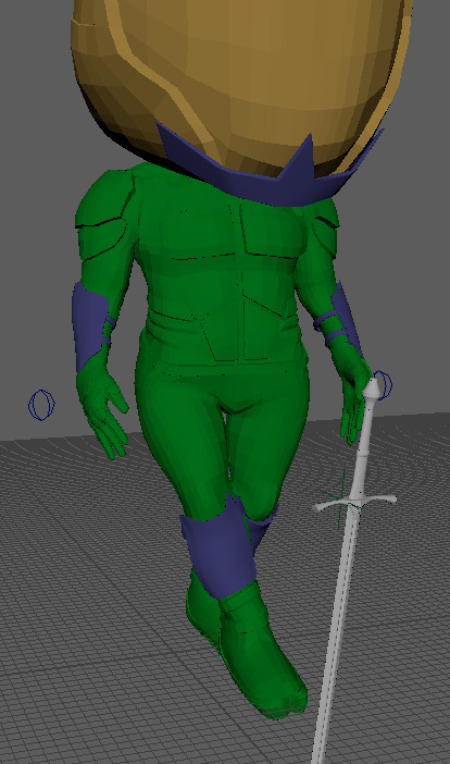
Figure 334: Animation Production 6
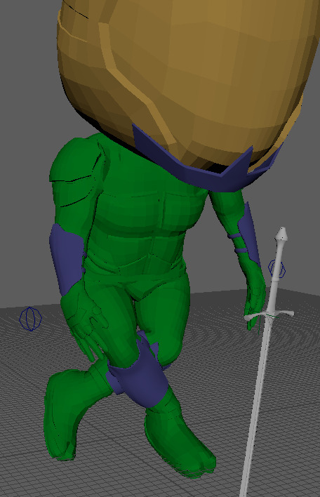
Figure 335: Animation Production 7
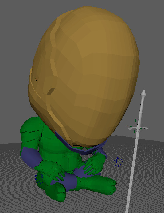
Figure 336: Animation Production 8
Within these poses there are a lot of smaller movements and adjustments in order to make the animation more realistic, such as the head movements as the character sits down in addition to the arms leaning forward. With this animation created I then moved on to start the meditation process, this animation did not really require any direct reference due to its simplicity, the first pose is simply the character raising both arms in anticipation.
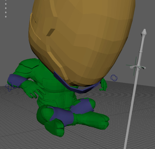
Figure 337: Animation Production 9
The next pose is the contact pose, connecting the fingers to one another, however, after creating this I realised that this section of animation looked too perfect when compared to the speed at which he connects his fingers, therefore, I added some frames of overlap to make the speed seem more realistic.
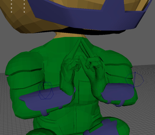
Figure 338: Animation Production 10
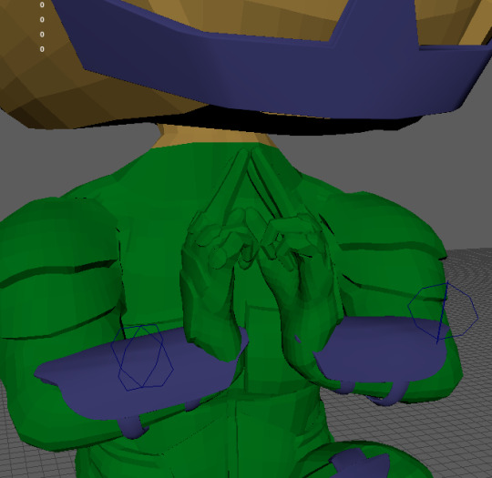
Figure 339: Animation Production 11
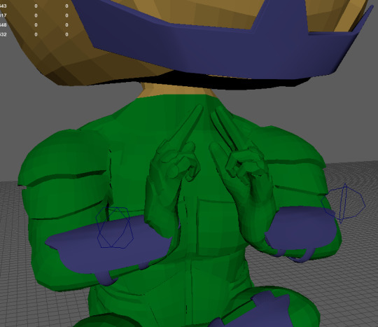
Figure 340: Animation Production 12
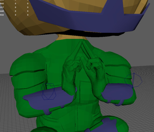
Figure 341: Animation Production 13
In doing this I initially did not animated the fingers and instead focused on the main movements within each pose, however, after completing the keyframes I moved onto create the hand animation using the set driven key method, therefore, allowing the character to grip the sword and also create the pose whilst meditating, along with other, smaller adjustments throughout the animation.
The final adjustments that I made to the animation since the previous post, has to do with the legs, in certain areas the legs would slide across the ground, which is not possible within reality when referring to the respective actions taking place. I had always intended to adjust these, as the only reason they are within the animation is just to the lack of in between frames within these areas, therefore, I added in between frames to the legs, lifting them up and positioning them accordingly to create steps.
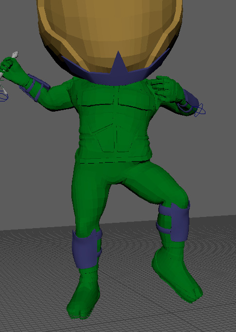
Figure 342: Animation Production 14
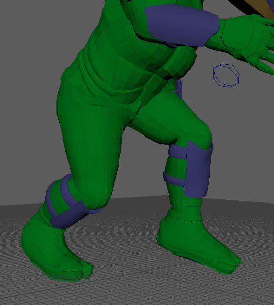
Figure 343: Animation Production 15
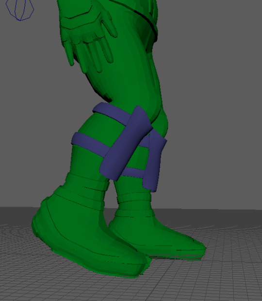
Figure 344: Animation Production 16
0 notes
Text
3D Character Modeling & Animation - Day 32
Over the past week I have managed to finish the skinning process for my character, skinning the spine and the head. Within the previous blog post I was struggling with skinning the spine, however, I have managed to overcome this issue through some advice from my animation tutor, he suggested to tackle the spine in stages, starting with the first joint and flooding it with white, repeating this process for the rest of the spine joints and then smoothing in between each section, in turn creating a smoother transition and curve between the spine, allowing for clean deformation. This did cause some issues when bending the character forward, with some of the armour plates moving down into the character on extreme bends, however, it was a much better result then my previous attempts.
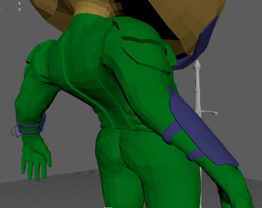
Figure 324: Skinning 17
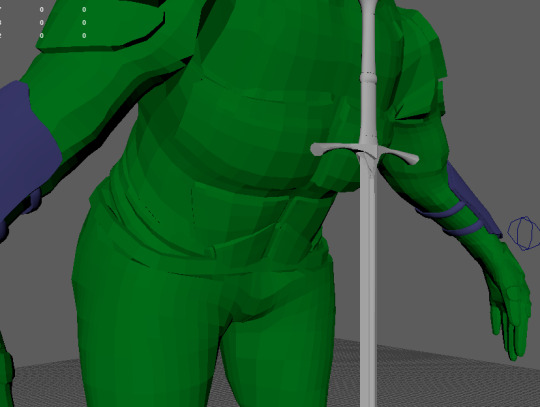
Figure 325: Skinning 18
The head on the other hand was a lot easier then I had anticipated and followed the same rules as with the leg or arm, however, in reverse.
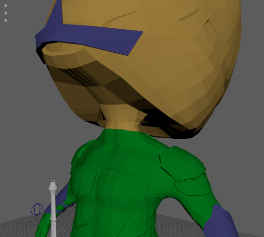
Figure 326: Skinning 19
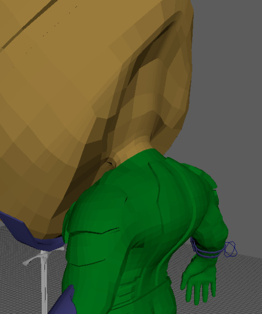
Figure 327: Skinning 20
With both of these elements complete, the skinning process was concluded, allowing me to mirror the skinning over to the other half of the model using the Mirror Skin Weights tool, upon doing this I noticed some minor issues that could potentially be resolved. The first issues was to do with a line of vertices that seemed to have no skinning applied within the middle of the character’s crotch, this can be fixed be adding skin to these vertices. The second issue was to do with the left right leg, when the leg was bent the joint around the knee would not move in the same way as with the opposite leg, even though the joints were mirrored over to one another. It appears as though for some reason the joint within the right leg of the character is not orientated to the correct axis, resulting in some odd deformation, however, this deformation is not inherently bad and still appears as if the knee is bending. Attempts were made to fix the orientation of the joint, however, it was not possible to adjust the joint without removing the skin, thus causing the skinning process to be reverted, therefore, I decided to leave it as it is.
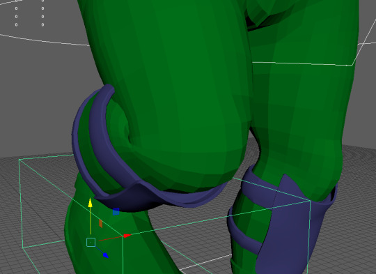
Figure 328: Skinning 21
Upon discovering these issues, however, I was advised to first start animating the character, posing him within the key frames of the animation and see how the skinning reacts and then afterwards go in and adjust anything that may be causing issues, therefore, creating skin specifically for the animation.
With this advice I started animating, overall getting the first three key frames complete. The animation process, relies mainly on the animators ability to observe and recreate human movement onto a character, following the twelve principles of animation in the process. Doing this requires a lot of experience within the field of animation in order to develop of fluid and realistic looking animation, this is something I do not posses, the overall experience of animating. Therefore, I can only animate to the best of my ability, however, the overall process of posing the character within the key frames has been made a lot easier thanks to the control rig that has been created.
The first pose of the animation see’s the character holding his sword in front of him with both hands, with the sword pointing toward the ground. Therefore, using the control rig I posed the character in this way. As this pose is the initial pose of the animation there is no transition between the pose, allowing for the key frame to be set on frame zero, locking this pose as the default of the animation, when posing the character I did not animate the fingers, this is due to the fact that I have not created a set driven key for the fingers as of yet, however, it also because the overall animation of the character needs to be the main focus and not the smaller details such as the fingers, these details can be added and adjusted near the end of the animation if needed.
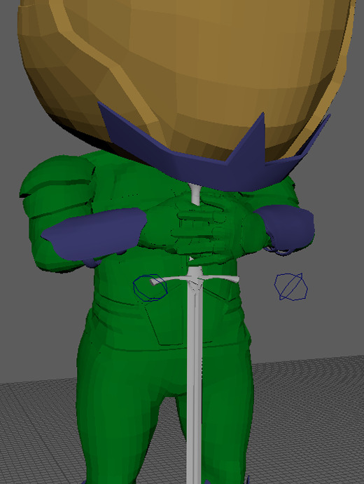
Figure 329: Animation Production 1
After posing the character, I then needed to create a selection set for the control rig, this was performed in a similar way to the bones, selecting all of the control rig and creating the selection set, the purpose in doing this is to confirm the pose throughout the whole rig, avoiding any are of the rig accidentally performing the wrong animation, applying the key frame to the whole rig allows for the animation to be consistent.
I then created the next key frame of the animation, this is where he draws his sword up in preparation to thrust it into the ground, this keyframe required some adjustments from what was originally planned due to how the character is designed, due to having an oversized head, lifting the sword vertically is not possible without it clipping through his head, therefore, I have changed the pose to instead lift the sword with one hand, moving it back and out as if he is drawing his arm back. Initially with this pose I mainly focused on the hand and torso, however, this was an incorrect approach, resulting in a very unrefined and unrealistic pose. After receiving some feedback from my tutor about the pose I then made some adjustments in order to fix it, I first started by unlocking the rotation on the root control allowing for adjustments to the rotation of the characters upper body, creating a twist as he draws his arm back, I then rotated the feet and then moved the spine controls back creating more of a lean, adding slight exaggeration to the lean, to increase its effectiveness. In doing this pose I also parented the sword to the wrist joint of the character, causing the sword to move with the arm, simplifying the animation process.
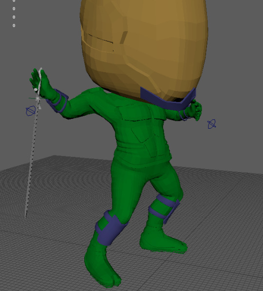
Figure 330: Animation Production 2
Using the tips given by my tutor I had no real issues creating the next pose which is the impact pose, with the character thrusting the sword into the ground. When doing this I first reset the values of the control rig back to zero in order to work from the base pose of the character, I then moved the control rig into the pose, making sure to emphasise the lean of the character as he strikes the sword into the ground.
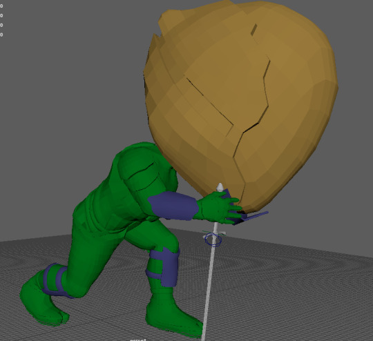
Figure 331: Animation Production 3
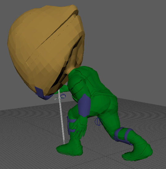
Figure 332: Animation Production 4
0 notes
Text
3D Character Modeling & Animation - Day 31
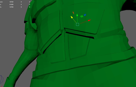
Figure 318: Skinning 11
Since the previous blog update, a small amount of progress has been made on the skinning of the character. As of last weeks post I left off at the start of skinning the hand of the character, struggling to understand why It would not work as intended, however, as of now I have managed to overcome the issue and finish the skin for the hand. In order to fix the conflicting elements when skinning the fingers I simply just manually painted the skinning weights for all of the fingers individually instead of letting the software try and do it with the smooth option. Using the smooth option does a general smooth around the overall area, causing it to enter areas that are locked causing the skinning to bleed over slightly, therefore, I went through each layer for each finger in order to find any stray weights were they should not be and removed them. I then went through from the middle finger to the little finger and painted the weights by hand in order to achieve clean results. However, doing this still produced issues similar to using the smooth option, however, they were also easier to cleanup due to knowing what layers they could have bled into. Whilst creating the skin for the hand I also needed to adjust the position of the joints within the fingers to match the edges that I had created to provide a smooth and realistic bend within the fingers. Some of the joints were slightly miss aligned on both hands, unfortunately due to the skin being bound to the joints, moving them would resulting in the mesh moving along with it, however, there is a tool that allows for this to happen without adjusting the mesh, this tool is called, “Move Skinned Joints”.
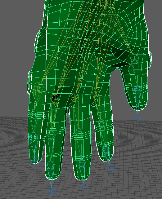
Figure 319: Skinning 12
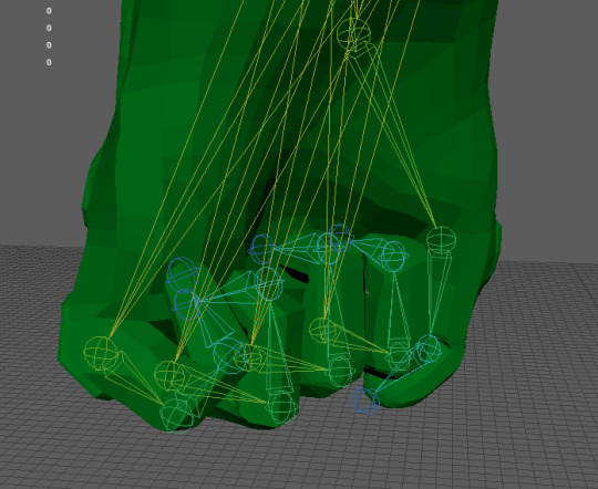
Figure 320: Skinning 13
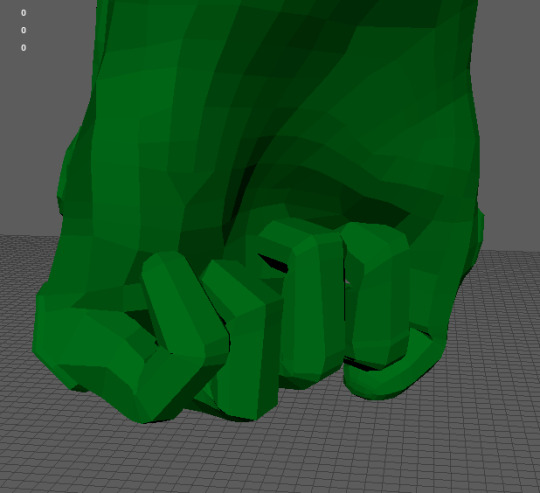
Figure 321: Skinning 14
With the hand complete, I then moved onto the spine, the overall skinning process for the spine is similar to that of the other areas of the character, a linear progression down through each joint, however this is done in reverse, due to the main skinning being applied to the bottom of the spine. When skinning the spine I have encountered some issues that I am unsure how to resolve, these issues are mainly in relation to my inexperience with skinning characters as I am unsure as to what is the most effective method of skinning the spine. Currently I have produced the skinning for the first and second spin joints, however, when the joints are moved using the control rig, the second spine has a tendency to overlap the first spine joints be a significant margin making it appear unnatural and overall distorting the mesh, I have attempted many times to create a smoother transition between both joints however to no avail, there are some ideas I do have to fix this issue that I still need to attempt, however, I am unsure as to if they will be effective. If they do, however, end up having no effect I will resort to asking my tutor for some assistance so I can finish up the skinning for the character and move onto animation, as the deadline is closing in.
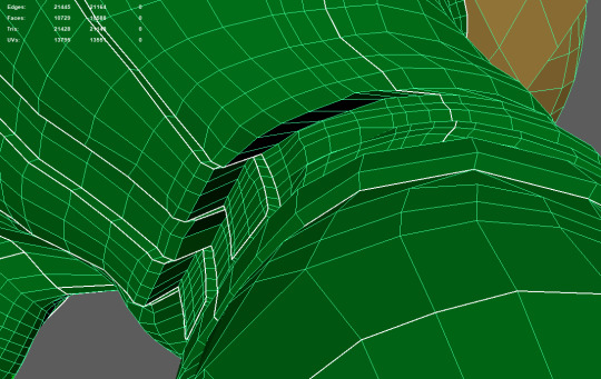
Figure 322: Skinning 15
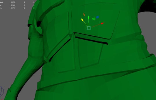
Figure 323: Skinning 16
0 notes
Text
3D Character Modeling & Animation - Day 30
Within the week since the previous blog post, we have gone through the process of skinning the character, the skinning process designates certain areas of the character mesh to certain joints, allowing for clean deformation of the mesh when it comes to animating. The overall process of applying skinning weights to specific areas of the character can seem complicated at first, however, once the basics are learnt, the rest of the skinning process should be self explanatory. This is the case in theory, however, during the time I have spent skinning my character there are certain areas that I am unsure of and or do not work correctly, that I will get into further throughout the post.
In order to apply skinning weights to a character the joints must be bonded to the mesh by selecting the relevant joints in conjunction to the mesh and selecting bind skin, this will allow for the joints to control the mesh. Next, the mesh of the character must be selected again, however, this time selecting paint skinning weights, clicking this option will display a new menu with the entire joint hierarchy that is attached the selected mesh, the mesh may also appear black when this option is selected. Skinning uses values between black and white or 0-1 in order to determine how much the assigned joint will effect the mesh when it is manipulated during animation with black not effecting the mesh and white effecting the mesh. The initial steps to set up the skinning process is to set a master control for both the upper and lower body, these master controls are the pelvis for the lower body and the first spine joint for the upper body, therefore, through selecting the pelvis joint within the pop up box and flooding the joint with a white value it deems the pelvis the controller for the whole mesh, then to set up the upper body control we select the vertices of the mesh for everything above the waist, then select the spine joint and flood that with white, therefore, the skinning of the body is halved making the process a lot easier to understand.

Figure 308: Skinning 1
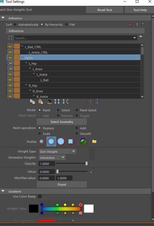
Figure 309: Skinning 2
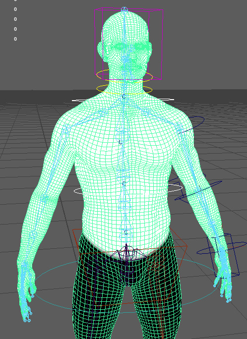
Figure 310: Skinning 3
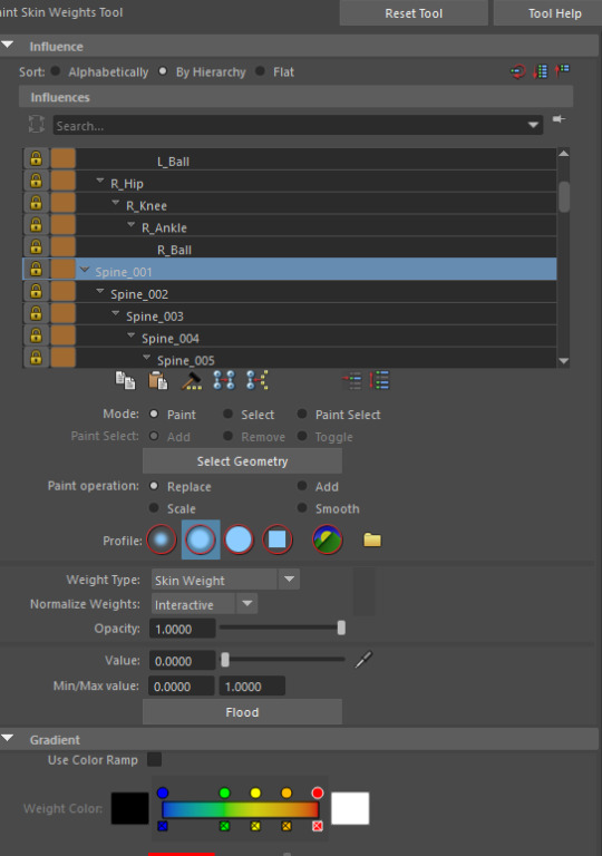
Figure 311: Skinning 4
With the skinning process halved into two sides, this is also how it will be tackled, by first either doing the arm or the leg, I chose to do the leg on the practice character, therefore, I unfortunately did not get around the practising the arm before applying the techniques to my character. Before skinning of the leg can begin, all of the skinning layers should be locked besides the areas currently being worked on, in this case it is everything except the pelvis and hip joints, the process of skinning is simplified through going one joint at a time, starting with the hip and working down the leg ensures each individual joint functions correctly rather then working on the whole. Therefore, the hip bone takes full control of the leg, this is again done through selecting the required vertices and flooding it with a white value. With the white value inserted, the smooth tool within the skinning menu can be used to smooth the transition between the skin. However, this has to be used sparingly as within human movement there are many intersections of skin that can be replicated with harsh skinning, therefore an effective balance between both need to be found for each joint.

Figure 312: Skinning 5
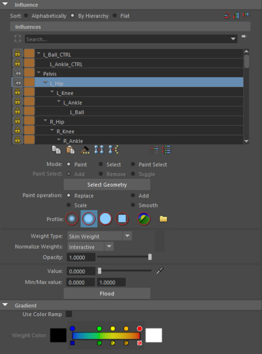
Figure 313: Skinning 6
This exact process is continued for the rest of the leg, however, with each joint that is skinned the previous joint is locked in order to avoid conflict with that layer, for example, when moving on to skin the knee the hip joint will be locked in order to avoid any changes being made to that layer.
This is all I managed to do during the practice session of skinning the character, before transferring the skills I had learnt over to my actual character, in doing this I have only managed the skin the leg and the arm, however, I have not been able to skin the fingers due to some complications. The legs for my character were produced in the exact same way as with the practice character, however, more refined in order to achieve better deformation in the mesh at different angles and positions.
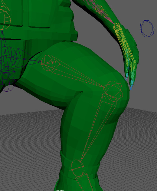
Figure 314: Skinning 7
The arm was slightly different and overall more difficult when compared to the leg primarily due to the complex interaction between the clavicle and the shoulder joints and the ways in which they effect the muscles of the character and also one another. This combined with the armour plating positioned on the shoulder meant I had to put a lot of care into the deformation in order to avoid bends within the mesh and also clipping. Due to this, both the clavicle and the shoulder required me to hand paint a lot of the skinning weights directly onto the mesh as opposed to primarily using the smooth option. However, the overall selection process for the mesh was the same, selecting the required vertices and flooding that area with white, due to the arm being within the upper body I had to unlock the spine joints as it is the master for the upper body. Before making adjustments to the clavicle I decided to also add the shoulder skinning so that I could manipulate them at the same time in order to get an effective deformation, this took a lot of back and forth switching between both joints fine tuning the values. However, in the end I managed to produce a very good deformation that will work well. The elbow, forearm and wrist are then produced in the same way as most of the leg joints, in doing this I started coming across some issues that were also present within the demonstration, namely around the forearm and wrist area. When applying a smooth to the skinning of the wrist it would in some cases cause the forearm skinning to reset for an unknown reason, this in turn causing the mesh to deform very poorly. My work around for this issue was to manually paint some of the weight in closer to the forearm in order to avoid conflict between the two, however, I am unsure as to why this happens as it is the same process as with the clavicle and shoulder, but it decides to not work around this area for some reason. In addition to this, the wrist is unable to rotate 180 degrees without the mesh pinching in an extreme way causing a sausage like effect due to the twisting in the mesh, I am unsure how to fix this. A similar issue emerged when creating the skinning for the fingers, however, I believe that I may have made a mistake when skinning them, but I am unsure if this is the case, since the issue did not visually alter the skinning dramatically, but would, however, adjust the skinning of locked layers when using both the smooth and manual painting of the skinning weights. Due to this I am going to discuss solutions with my tutor during the next session in order for it to get resolved quickly allowing me to finish the skinning process and move onto animating the character.
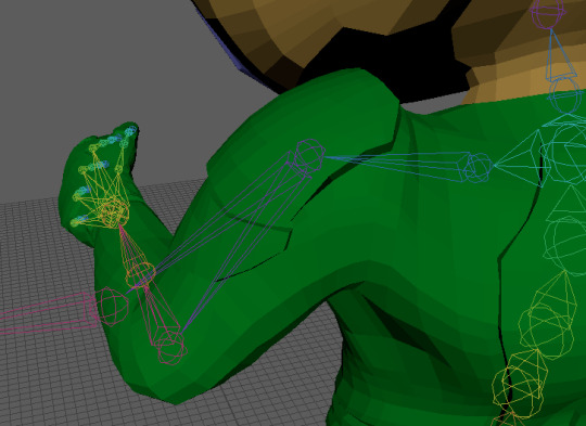
Figure 315: Skinning 8
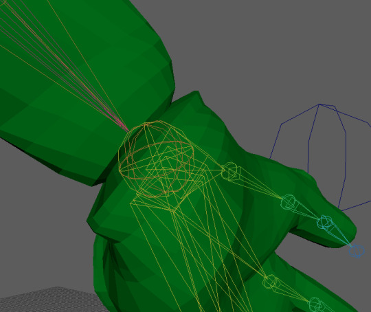
Figure 316: Skinning 9
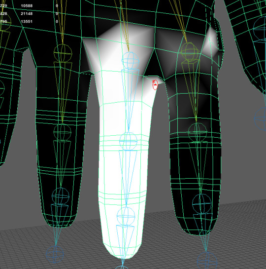
Figure 317: Skinning 10
0 notes
Text
3D Character Modeling & Animation - Day 29
After finally returning after a week off from University we have returned to producing the rig for the character, picking up for where we had left off, we finally moved onto creating the rig for the arm, this process seems a lot more complex then anything that we had done before due to the fact that two extra arms need to be created. The purpose of these extra arms serve is to act as the FK and IK options that can be used within the animation process, with this we also created a switch allowing the arm rig to be swapped on the fly. However, before creating the extra arms for the character, we created the control for the clavicle bone, as the clavicle is a universal bone between each of the three arms for the character allowing for it to be created beforehand. The clavicle control is created using the same method as the previous controls, through grouping and parenting it to the respective joint to acquire the correct orientation, however, once this is done, it is re positioned through the use of the control vertex much like how the knee control was, mainly to make it easier to select. With this the first additional arm can be created, the first arm we created was for that of the FK controls, therefore, we started by duplicating the shoulder joint, doing this duplicates the whole hierarchy of the arm, however, elements of the arm are not needed, such as the fingers and the forearm bone, therefore, they can be removed. With these elements removed, renaming the joints was recommended in order for them to be identifiable from the original set of joints, therefore, FK was inserted into the name. With the arm duplicated the same process is followed to link up the control rig to the joints, however, within the elbow joint there are some differences, when applying the orient constraint to the joint instead of assigning the constraint to all axes it is instead limited to one axis due to it only being able to move/rotate in one direction, for me this was the X axis.
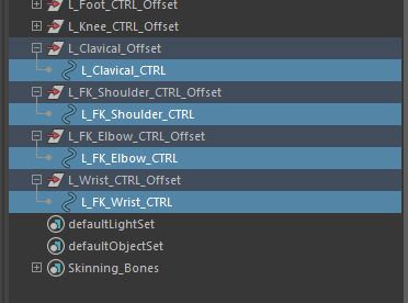
Figure 293: Rig Creation 30
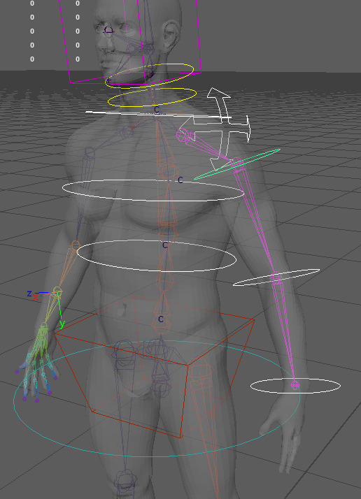
Figure 294: Rig Creation 31
With the FK bones linked up to the controls, through orient constraints, the bones are then duplicated again to serve as the IK bones, once duplicated the extra constraints are deleted as they are not needed for the IK rig. The bones are again renamed this time replacing FK with IK. Upon doing this an IK handle is then created between the shoulder and wrist joint of the IK arm bones, then another control is created following the parenting process in order to gather the orientation, however, instead of constraining the control to the handle, the handle is instead parented to the control, allowing for the IK handle to be controlled by the control rig. One constraint is applied to this control, this constraint is linked to the wrist, allowing for it to be rotated using the IK control. With this, much like the legs another control is added for the elbow and is linked to the IK handle created for the arm using a pole vector constraint.
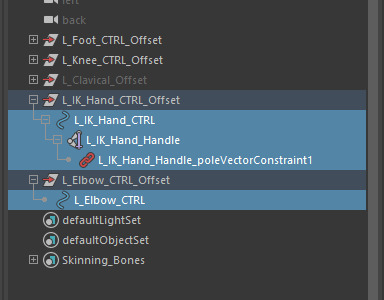
Figure 295: Rig Creation 32
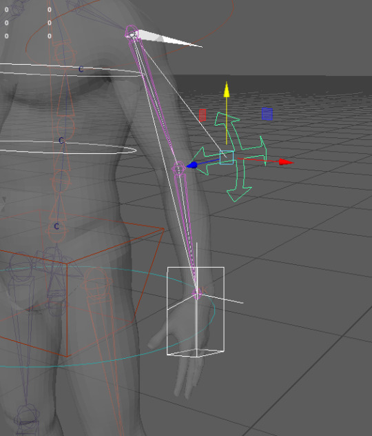
Figure 296: Rig Creation 33
With both additional arms set up for the character, we could now create the switch between the two options, to do this all of the arm joints and their respective controls were made visible, I then re positioned them so that I could see what was what. Then the joints of both the IK and FK bones were constrained to the original bones of the arm through and orient constraint, thus assigning both arm joints to one constraint.

Figure 297: Rig Creation 34
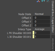
Figure 298: Rig Creation 35
With the constraints assigned to the bones an attribute is then added to the master control called L_FK_IK_Switch, with L being interchangeable depending on the respective arm, the values associated with this attribute are that of a float value between 0 and 1, anything above a maximum of 1 seems to break the switch between both rigs. With the attribute assigned to the master control the node editor is used in order to link the switch between the FK and IK rig, opening the node editor with nothing selected will result in it being blank, with this the master control and the previously created orient constraints need to be imported, upon importing these elements into the editor each node will have a clickable box within the top right of the node, clicking this opens more options associated with that node. the group of the master control will have the FK, IK switch attached to it, to access this it must be clicked twice, whereas the constraints they only need to be clicked once. The first set of node options that are linked, either FK or IK will be off by default, therefore, this is where you can choose what option you may prefer to start with, I personally chose FK, therefore, I linked the switch to IK. Next a reverse node is required, to create a new node hold right click and drag up with the mouse, then in the text box type reverse, like the other nodes it can also be expanded, in this case it needs to be expanded twice, the switch is then linked to an input and the output is linked to the opposite rig, therefore FK. With this the FK, IK switch had been created.
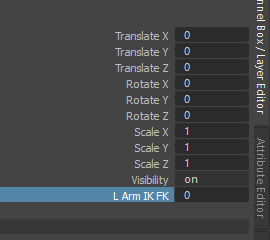
Figure 299: Rig Creation 36
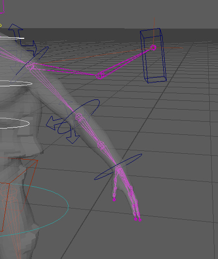
Figure 300: Rig Creation 37
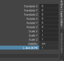
Figure 301: Rig Creation 38
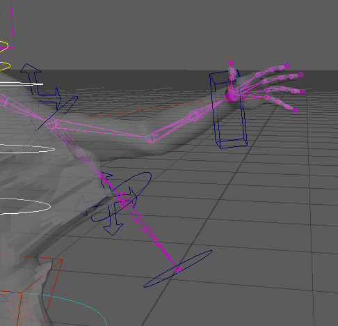
Figure 302: Rig Creation 39
Next a control over the forearm bone was applied to the wrist control in order to create a realistic twist with the arm. This was done through creating orient constraints within the original arm bones, through creating a constraint between the wrist and forearm bones and the elbow and forearm bones It is able to calculate half of the rotation value of the wrist rotation, creating a more accurate effect when rotating the wrist.
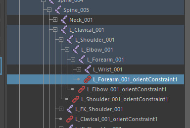
Figure 303: Rig Creation 40
With this the base default rig for the character had been complete, due to this we moved onto creating the hierarchy for the rig, therefore, allowing elements of the rig to control one another, similar to how the rig for the head functions but throughout the character. Doing this also links all of the components to the master control in some way, allowing for the whole rig and character to be moved as one throughout the scene which is useful for moving the character during animations. Some of the more individual elements of the rig have been situated into their own hierarchy, therefore, simplifying the process. The first stage of the hierarchy removes the curve from the master control and instead parents the root control to it, doing this produces the same effect as if the curve was still parented to it, however, replaces the curve with a control rig element that can be used to move the root bone, which in turn effects other elements such as the spine. Next the pelvis is attached to the root control offset through the use of a point constraint, this constraint acts as any other constraint would in its application, however, differs in its use, from what I can gather it links the translations of both elements together. Therefore, through applying it to the offset of the control it does not effect any other control, allowing it to be attached and follow the rig. When applying the point constraint maintain offset must be checked to avoid any movement of the rig that could potentiality mess up the position of the character. Next the foot control is attached to the master control, doing this leaves the knee control behind due to the knee control acting as a point of reference for the IK handle controlling the leg, it should not move around, therefore, it is attached directly to the root control. The FK arms are then attached to the control for the top of the spine allowing them to move as one, however the IK controls are attached to the master control, the reason for this is so that if the spine were to move the hand would stay in the same position which is the purpose of an IK control. Next the elbow control is attached to the pelvis control offset to ensure that it does not move when elements are adjusted and finally the neck controls are also attached to the top of the spine. With this the hierarchy of the rig is complete, however this hierarchy is not set in stone, it can be adjusted in order to better fit a specific animation, therefore, I will keep this in mind when it comes to finally producing the animation for my character.
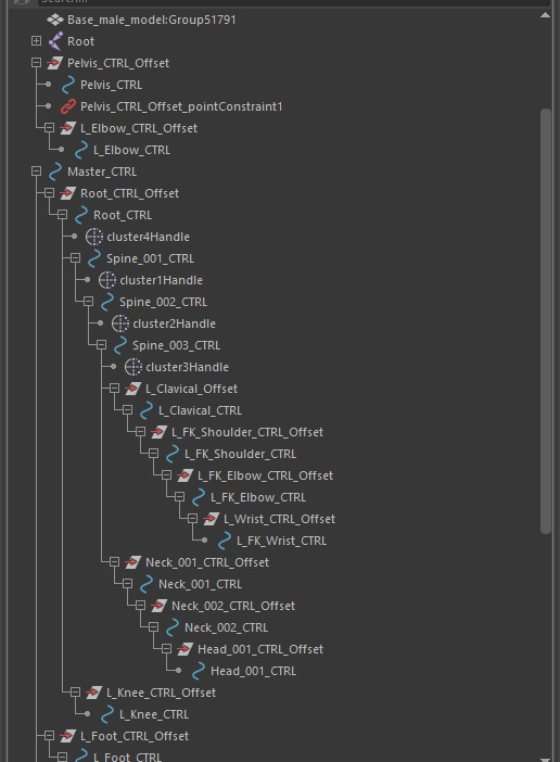
Figure 304: Rig Creation 41

Figure 305: Rig Creation 42
Like previous week’s, within my own time I have applied this process to my own character, as of now I have kept with the base rig, however, if I feel the need to change certain elements of the rig during the animation process I will not hesitate to do so as long as I know how to achieve the effect I desire and or need. Within the rig I have also produced the opposite side of the rig, therefore, giving me full control over the character.
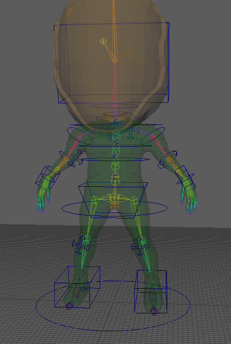
Figure 306: Rig Creation 43
In addition to finishing the character rig I also made some adjustments to the initial storyboard based on peer feedback aswell as feedback from my tutor, the changes made aim to clarify and finalise the overall animation choices aswell as rectify what direction the character is facing within each keyframe. The first change made to the storyboard was to adjust the keyframe as the character prepares to strike/throw the sword into the ground, previously I did not know what would be the most suitable option for the animation, however, peer feedback suggested it would be best for the character to strike the sword into the ground instead of throw it, therefore, I went with this decision. The second addition to the storyboard was plotting the face of the character within each frame, this aims to show what direction the character is facing, giving me a clear understanding of how to position the characters head when it comes to animating the character. This storyboard will now be the main source of reference for the animation.
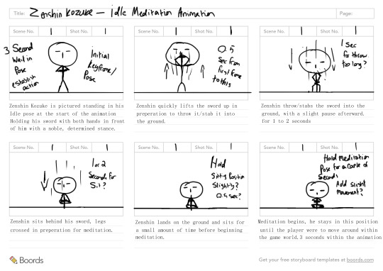
Figure 307: Final Animation Storyboard
0 notes
Text
3D Character Modeling & Animation - Day 28
Within the past two sessions that we have had covering the animation/rigging stage of production, we have started to delve into more of the animation side, looking through how to create a walk cycle using an pre rigged character. Within the first session we went through the animation process for the legs of the character to create the basis of a walk cycle that we could use to build upon, to do this we gathered reference of walk cycle’s and simply copied two poses from the reference, the poses we used were the pass pose and the contact pose. However, the reference image only accounts for one leg, therefore, we needed to flip the animation from one leg to the other in order to create a full cycle. In order to position the legs into the correct pose, we used the control rig, luckily the legs of the character have an IK rig set up allowing for posing of the legs to be simplified through just moving two elements, the feet and the hips. The first pose within the cycle is the pass pose, therefore, this was replicated, however, there were some small additions that needed to be made to the pelvis, when people walk the pelvis tends to drop in favour of the lifted leg, due to the pelvis having no support on that side, therefore, this also needed to be replicated in the animation.
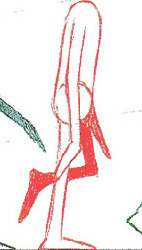
Figure 283: Walk Cycle Reference 1
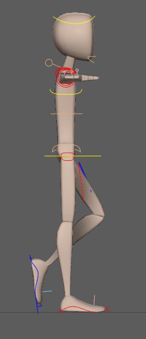
Figure 284: Animation Practice 3
The second pose used was the contact pose. The reason for only creating two poses of the walk cycle is that within 3D animation the software being used, in this case Maya, will create the in between frames of the animation as best as it can, therefore, creating a good base walking animation, however, there will be tweaks that need to be made to the animation in order to polish it, therefore, these poses are known as key frames, due to them being the main frames within the animation required in order to understand what is happening.
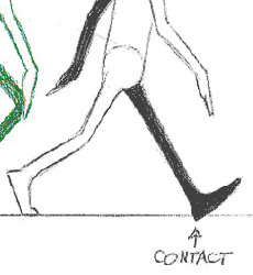
Figure 285: Walk Cycle Reference 2
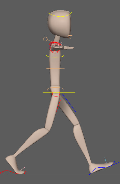
Figure 286: Animation Practice 4
These key frames then needed to be transitioned over to the other leg in order to create a full cycle/loop of the animation. To do this we essentially mirror the position of each element used within the animation through the use of the channel box, when moving the rig of the character the translation values are adjusted within the channel box, with this the adjustments are made using both whole numbers and decimal values, therefore, in order to simplify the process we were encouraged to adjust the values to whole numbers, rounding them up to the nearest whole. With this I then noted down the values and transitioned them to the other leg and vice versa, repeating both poses to create a full cycle.
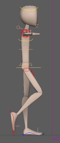
Figure 287: Animation Practice 5
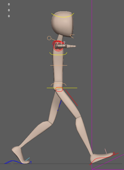
Figure 288: Animation Practice 6
With this initial animation created, we moved onto adding in the poses that we left out, these poses are called in between frames. Their purpose is to adjust the animation to add more realism and character. With the present key frames the character looks like they are sliding in some instances, therefore, adding the in between frames will allow for more impact and bounce to be shown within the movement. When creating the walk cycle and creating the key frames we used an interval of 10 frames between each pose, therefore, the in between frames of the animation were then positioned at the fifth frame in between the key frames. The process of creating the in between poses was relatively the same, as with the key frames and revolved around positioning the character in the same pose as the reference image. The first in between pose created was the Up pose. In addition to creating these new poses I also attempted to animate the arms of the character, whilst other members of my class caught up on the animation process.
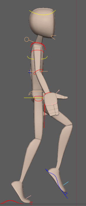
Figure 289: Animation Practice 7
The next pose was then the down pose, this pose comes after the contact pose, applying more impact to the character.
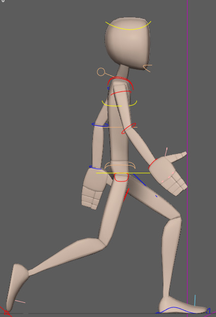
Figure 290: Animation Practice 8
With these additional frames added to the animation, we had some issues when the animation was played, parts of the animation would either snap in and out or be delayed slightly, some of these issues can be attributed to animation as a whole, however, a lot of them can be fixed within the animation graph editor. When animation curves are generated within the graph editor, some adjustments within the animation process can adjust the curve of the movement, ideally the curve needs to be smooth, however, sometimes it will not be. therefore, these curves need to be adjusted in order to make a smooth transition between frames of animation. The graph editor can be found within the windows tab under animation editors. Within the graph editor a list of transformations options will appear on the left of the window these options are attributed to the key frames of the animation, therefore, they depends on how the selected part of the control rig had been moved, for example, adjusting the curves of the hip control will only be applied to the Y translation due to it performing an up and down motion.

Figure 291: Graph Editor
This process was performed for more or less all of the components of the rig that were manipulated during the animation in order to create a smoother animation, however, the end result of my animation still ended up being slightly choppy in some areas, meaning that I am going to need to look into how this process is performed correctly.
Finally we went through the process of animating the arms of the character, even though I had attempted them before everyone else, there were still aspects of the animation that I did not take into account with the knowledge I had at the time, the main one being that the upper body sways with the arm movement and also that the sway of the upper body is opposite to that of the legs, in addition to this I had also produced the in between frames of the arm animations before finishing the key frames which ended up causing me issues further down the line. The overall animation process of the arms is very similar to that of the legs however, the arms are animated using FK controls as opposed to IK meaning that I animated from shoulder to wrist to position the arms in the correct pose.
Unfortunately, however, after positioning the arms in the correct pose and mirroring the poses for the opposite arm the create the loop I noticed some stutter in the animation of the arms that I could not get rid of. On the other hand, however, the animation looks nice and it looks like an accurate walk cycle for a character.
In addition to producing this animation I have also produced the initial storyboard for the animation idea I am aiming to create. The animation that I have in mind is that of an idle animation, where if the player is away from their controller/keyboard the character will sit down and begin to meditate. The reason I decided to go with this animation is primarily due to the 10 second limit in combination with the amount of time that we have remaining to produce the animation. This animation gives me a lot of room to display the personality of my character whilst reducing or extending the animation depending on how long it will need to be. The storyboard I have created is very simple and is drawn using stick men, the purpose of this storyboard is to depict whether the animation will work within the allotted time frame and also how long each action will take. Within the creation of this storyboard I have prioritised the main key frames that the animation will have. Overall I expect this idea to expand upon receiving some feedback from my tutor and classmates, however, for now this is the idea that I believe fits my character well.
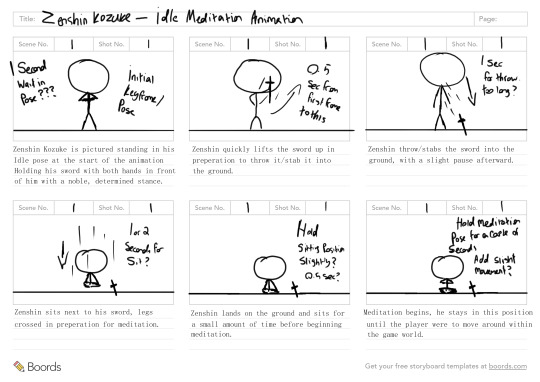
Figure 292: Initial Animation Storyboard
0 notes
Text
3D Character Modeling & Animation - Day 27
During this weeks rigging session we went through the process of setting up the control rig for both the spine and leg’s of the character. During the session we only rigged one of the legs in order to save time and allow for us to get both areas complete during the session, however, the process of rigging the other leg is the same as the first. Unfortunately unlike with the bones that were created previously, the control rig can not be mirrored, therefore, requiring it to be manually generated for both legs, this in turn warrants the same process for the arms aswell. The creation of the spine controls is similar in some way to that of the neck and root control, however different in many other ways. This is due to the addition of IK Handles, the spine of the character utilises a IK Spline Handle, that is created through the skeleton tab within the rigging section of Maya, in order to create the handle the top and bottom of a hierarchy chain must be selected. Upon doing this it will create a curve based on the selected options, connecting to other joints in-between. When creating the spline handle there is an option of note, this is the twist type of the IK handle, due to the spine having more rotation near the top of the handle, ease in is the twist option that is required, allowing the spine to “ease in” to the rotation. Creating the IK Handle, also creates a curve along with it, due to using it as a guide, however, this curve is also needed in order to position the spine controls that will be created, first, clusters are created using the control points of the curve to allow for easier selection when positioning the control rig points. Therefore, we move the curve into the master control and use the four control points of the curve to create cluster’s. After doing this we create comet shapes in a similar way to that the process performed last week, however, this time it does not require the offset group, due to the position of the pivot being unchanged, therefore, creating the comet shape whilst selecting the cluster is a viable option requiring less time. With the controls positioned their respective clusters must be parented to allow for the control points of the spline to be effected by the control’s, then in a similar way to the head the spine must be linked in a hierarchy to provide parented actions.
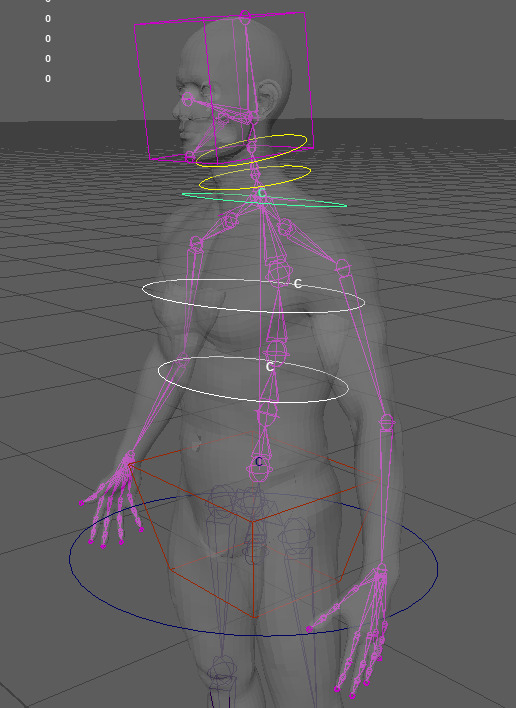
Figure 275: Rig Creation 22
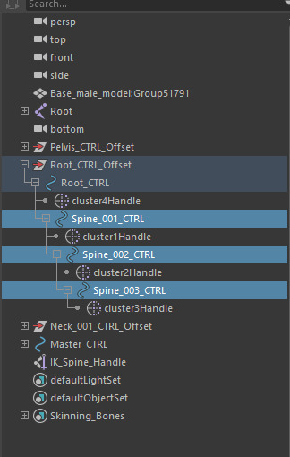
Figure 276: Rig Creation 23
With the spine created we moved onto the legs, creating the controls for the leg required the creation of a “reverse foot”, this is exactly how it sounds, essentially, the bones used for the foot are duplicated, an extra bone is inserted near the heel of the foot, with this bone inserted the skeleton is then rerouted, therefore, making it go in reverse, ie the reverse foot. The newly created bones of the foot will act as the controls instead of the original bones, therefore, they are moved to the master control to remove them from the bone hierarchy and promptly renamed as such, in addition they are also oriented along the correct axis due to them being new bones. With this, three regular IK handles are inserted into the original set of bones for the leg, one running from the hip bone to the ankle, the next from the ankle top the ball and the third from the ball to the toe. These IK handles are then parented to the new bones or controls created for the foot and renamed to their respective parent. With this done a comet shape is again created following the same process as the neck and head and parenting it to the heel control, this shape is going to be the main control of the foot, with the shape adjusted and un parented, the heel control and its hierarchy are then parented to the foot control due to it being the main control for the different elements of the foot. Next, we needed to add attributes to the foot control in order to control the different elements of the foot, the attributes created for the control go as follows: Leg Twist, Ball Roll, Toe Roll, Toe Twist. To create an attribute, the foot control must be selected, then clicking on the modify tab and clicking add attribute, within this option the name of the respective attribute can be entered, then the max, min and default values must be entered along with a data type, the data type that I used was called integer, this data type keeps the values to whole numbers when adjusted, making it easier to managed the numbers when editing an animation. The max min and default values for the leg twist are left blank besides the default value which is set to one, this value is consistent throughout the different attributes, however, changes are made to the min and max.
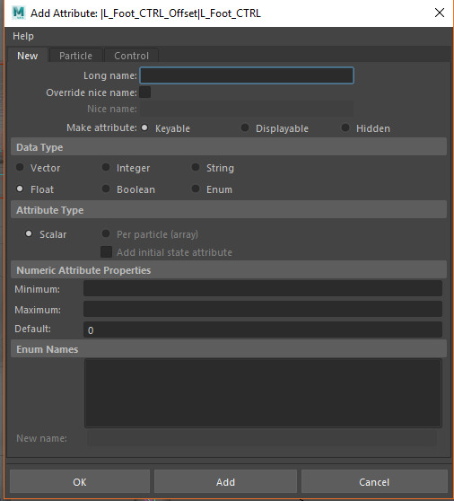
Figure 277: Rig Creation 24
Clicking add will add the attribute to the channel box, next through clicking on windows hovering over general editors the connection editor can be found, this will allow for the leg twist attribute to be linked to the IK handle of the ankle that houses the twist. The window that opens through the connection editor displays the attributes of the selected elements on the left, through selecting another element and clicking reload right, it will load the attributes of the second element, therefore, clicking the ankle handle and clicking reload right gives access to the twist function. Clicking leg twist on the left and twist on the right links these attributes together, causing the foot control to influence the IK handle twist attribute, this process is also used throughout each element, however, with different elements and attributes selected.
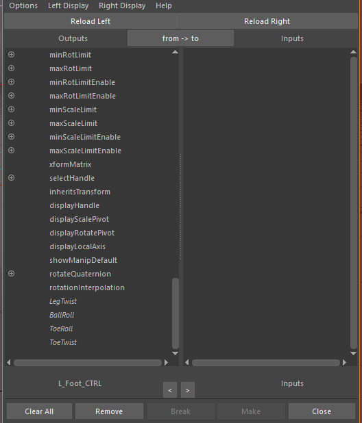
Figure 278: Rig Creation 25
Both the ball and toe roll follow a similar pattern to one another, first the attribute needs to be created, however, this time adding a 0 to the maximum value, due to the foot only being able to rotate in one direction when rotating on the ball and toe, the min value operates along the minus which is the rotation needed. Due to this the rotation of the joint is required instead of the IK handle along the X axis, therefore, this is selected when connecting them together. Finally the toe twist follows the same process as the leg twist.
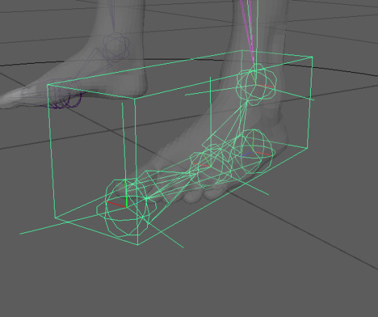
Figure 279: Rig Creation 26
The final stage we went through was adding a knee control to stop the knee from bending backward during the animation process, for this we used the orient shape and created an offset group parenting it to the knee bone. however afterwards moving it out along the Z axis in the world space from of the knee and using a pole vector constrain to the IK handle of the leg.
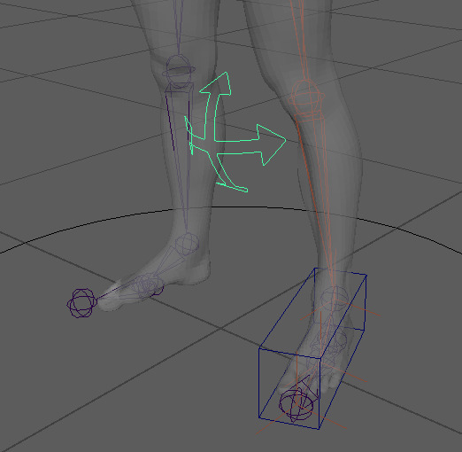
Figure 280: Rig Creation 27
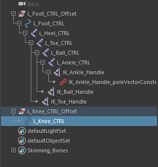
Figure 281: Rig Creation 28
With this knowledge gained I again went through the process with my own personal character, creating the other leg control rig along the way.
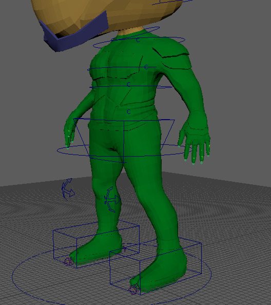
Figure 282: Rig Creation 29
0 notes
Text
3D Character Modeling & Animation - Day 26
During this weeks session we moved onto creating elements of the control rig for the character, unlike with bones, the control rig is what will be used during the animation to control the different areas and joints, utilising NURBS allows for isolated transformations within the control rig that can be reset without directly effecting the character model, therefore, resulting in fewer complexities during the animation stage. The areas of the control rig that we covered during the session consist of the master control, the root control, the pelvis control, and the neck and head controls. Overall these controls are relatively easy to set up.
We started by creating the master control, the master control is primarily used to reposition the character within the scene, due to this, the control is positioned at the feet of the character with a sizeable scale attributed to it making it easy to select. The NURB shape that was used for the master control is a circle, available through a set of scripts that were provided to us called “comet”, one aspect that we were encouraged to get used to was renaming the different elements of the rig as we go along to their respective attributes, much like what was done with the bones, renaming will allow for easy identification of each part of the control rig, making for a more efficient animation pipeline.
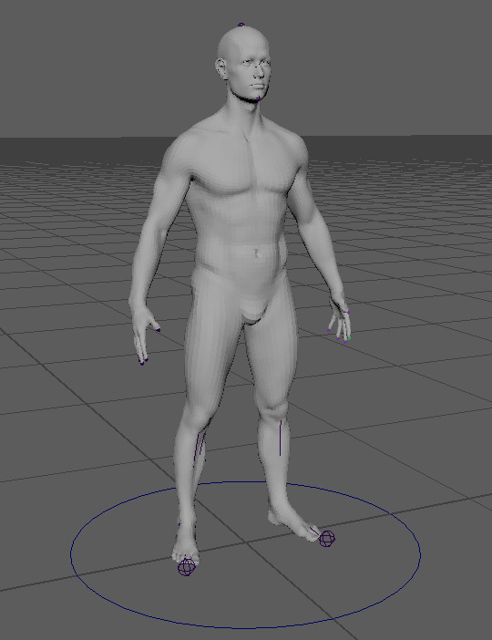
Figure 265: Rig Creation 12
With the NURB created for the master control, we moved onto creating the root control, the process of applying the root control to the rig is more complicated then that of the master control, mainly due to the fact that we only created and named the master control, whereas we need to attach the root control to the bones so that when the control is moved the bones move with it. To do this we follow the same small process as with the master control, however, afterwards place the control in a group, this is done because the control needs to be repositioned to the root bone, using the group allows for any translations to by pass the control and only effect the group, keeping the values of the control at 0 or 1. This is important for resetting the rig back to its original state during an animation. In order to position the root control correctly, the group must be parented to the root bone, doing this applies the transformations made to the root bone onto the group. Therefore, resetting the transformations of the group will cause it the be positioned where the bone is, this process is applied to each of the controls within the rig. With the control in position the group can be unparented from the bone, in order to allow the control to effect the bones, they must be constrained, due to the root bone requiring translation a parent constraint is required, constraints can be found under the “ Constraint” tab within the Rigging toolbar. Selecting both the bone and control and applying the parent constraint will cause the control to effect the bone, with this effect applied we were again encouraged to lock any transformation options that would not be used for that control to avoid potential mistakes when animating. This process was applied to the other controls created aside from a small difference in the constrain, with the pelvis, neck and head bones orient constraint is used instead of parent due to it only requiring rotation.
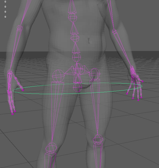
Figure 266: Rig Creation 13
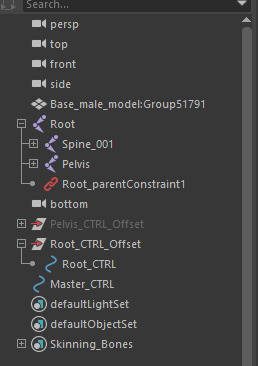
Figure 267: Rig Creation 14
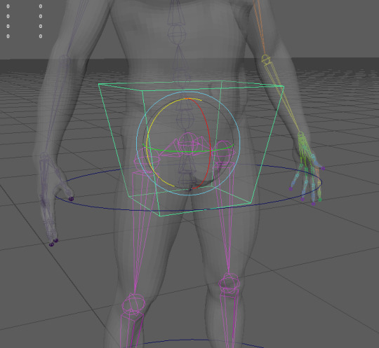
Figure 268: Rig Creation 15
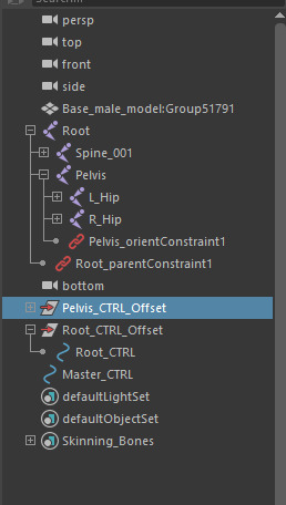
Figure 269: Rig Creation 16
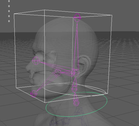
Figure 270: Rig Creation 17
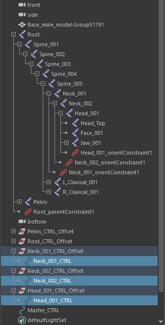
Figure 271: Rig Creation 18
After applying these controls to the bones of the character, we went through the basics of linking them together into hierarchy, allowing one control to effect another, this is performed through parenting them to one another, for the example we used the neck and head controls, due to them being self explanatory in how they function, the link started with Neck_001 attached was Neck_002 and attached to that was Head_001, therefore when Neck_001 is selected and manipulated Neck_002 and Head_001 will also be effected in the same way.
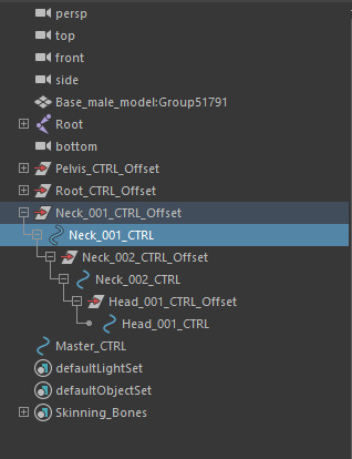
Figure 272: Rig Creation 19
Much like with last weeks session I applied these techniques to my own character.
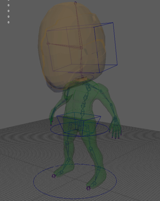
Figure 273: Rig Creation 20
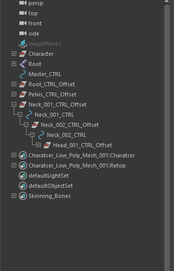
Figure 274: Rig Creation 21
0 notes
Text
3D Character Modeling & Animation - Day 25
During this weeks animation session, we went through the process of setting up and applying bones to a character mesh. This process is relatively simple, however, it is only the first stage of many that are required to set up an effective and efficient character rig that can be used to generate animations. In order to generate the bones for the rig the tab within Maya must be changed from “Poly Modeling” to “Rigging” changing the tab to this option will change the elements of the tool bar to tools that are used for generating rigs. The main tool used during this process is called “ Create Joints”, this tool, when used generates a sphere separate from the character mesh, within Maya it acts as a different entity to that of polygons, due to this it can be placed inside of the character, acting as the different joints within the body. However, they do not act as just the joints within the body, in some cases more or less “joints” will need to be added depending on what the rig is needed for, this idea will be explored later in the post.
With the ability to create joints or bones we started with creating the “Root” bone of the character. The root bone is the bone that the rest of the rig will be inside of, the root bone will allow for overall adjustments to be made to the whole rig through selecting the root bone. These adjustments will primarily be in the form of translations and rotations allowing for the character to be moved using the rig as opposed to moving the character separately. The root bone is positioned just under the pelvis of the character so that it does not get in the way of other bones that will be placed later on. With the root bone positioned it is used to generate the spine, selecting the root bone five more joints are generated throughout the spine in different positions to create a realistic bend within animation, the first joint stemming from the root bone is positioned just above the character’s bottom to act as the bottom of the spine, the second joint is positioned between the bottom of the spine and the ribs, the third is positioned at the bottom of the ribs, the fourth is positioned at the shoulder blades and the final bone is placed the the top of the spine/base of the neck. When placing these joints we took into consideration the overall light “S” shape that the spine has, however, in some cases this is not necessary. During the process of placing the joints, we were encouraged to name everyone of them as we go relative to the respective body part they will be controlling, this is to ensure that if a specific joint is require it will be easy to find, as later on into the process here will be a lot of bones to manage.
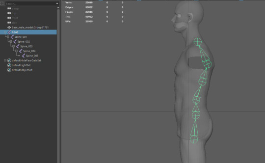
Figure 254: Rig Creation 1
After placing the bones, we needed to orient them to the correct axis to allow them to rotate in the correct direction relative to the characters current position in the scene, this was performed through the use of the “Orient Joints” tool. This tool is found through again changing the modeling tab within the drop down box to rigging, this is different to that of the toolbar and is found at the top left corner of the screen, orient joints is then found under the “Skeleton” Tab. In order to see what direction the joints are facing in relation to the world axis the option called “Toggle Local Axes Visibility” must be selected whilst he joints are selected, the goal when setting the orientation of he axes is to align it to that of the world axes to allow for animations to function correctly. Therefore, when selecting the the joints of the spine I set the orientation to have the primary axis as Y and both secondary axes as Z to match the world axis. This process was then repeated for most of the joints that were created for the character, some joints, however, utilised Z as the primary axis and Y for the secondary axes due to their angle and position.
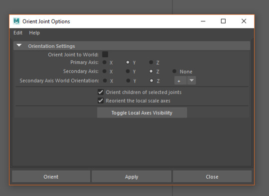
Figure 255: Rig Creation 2
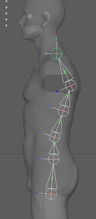
Figure 256: Rig Creation 3
With the spine created we moved onto creating the joints for the legs of the character. In order to create the legs we first needed to create the pelvis, this was done through a separate joint positioned above the root bone, from this bone stemmed the leg joints, the main joins within the leg are the hip, knee, ankle, ball of the foot and the toes, therefore, this is where the bones were positioned. When creating the joints for the leg I only generated one leg (the left leg) and then mirrored it over to the other side of the character, using the “Mirror Joints” tool, in doing his it allows for the names of the duplicated joints to be adjusted, this allows for both the left and right side of the character to be named as such, this is shown through both L_ and R_ respectively within the outline. Before the joints could be mirrored, however, the leg was required to be positioned within the hierarchy, through attaching the pelvis to the root bone.
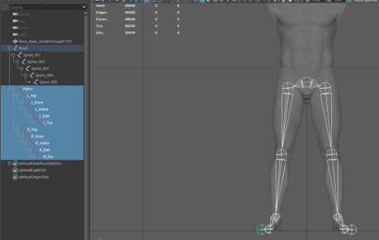
Figure 257: Rig Creation 4
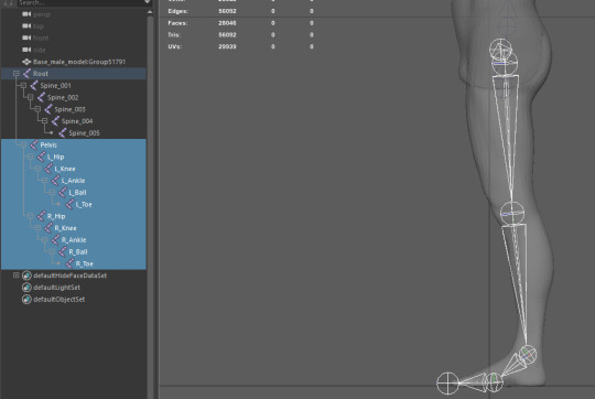
Figure 258: Rig Creation 5
With both of the legs created we moved onto the head. The head is one of the areas that can contain more or less joins depending on what the rig is needed for, however, due to demonstration purposes we went through the main ones that could be used, we first started at the neck, creating three joints leading up the neck to behind the ear of the character, stemming from this another joint is positioned at the top of the head and another is positioned at the characters face, these are the primary joints found within the head, however, we went through some optional joints, these being the jaw and chin, much like with the previous two joins the jaw and chin stem from the head joint. With the joints laid out they are added to the hierarchy under Spine_005.
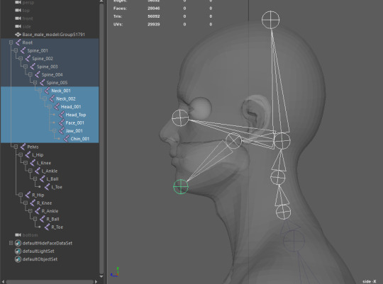
Figure 259: Rig Creation 6
With the head complete we moved onto the arm and hand of the rig, this followed a similar process to the legs of the rig, however with a few additional joints, the joints within the arm start from the clavicle bone or shoulder blade then the shoulder then the elbow and then the wrist, the placement of these joints is relatively self explanatory.
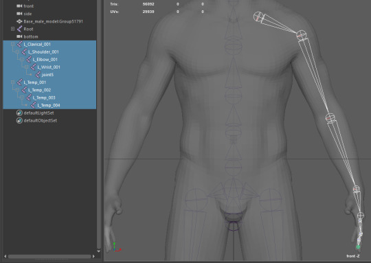
Figure 260: Rig Creation 7
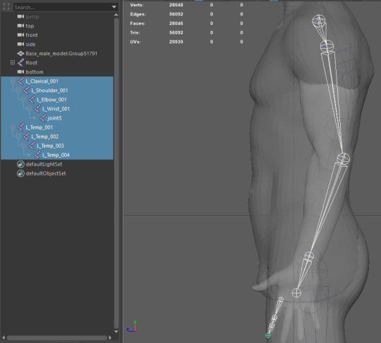
Figure 261: Rig Creation 8
The fingers of the hand were also done in a similar way, through placing the joints where the joints of the fingers would be, when creating the bones for the fingers we first create a singular finger and then duplicate the bones to fit the other fingers, making small manual adjustments to the position of the bones to fit the individual fingers correctly. With the fingers generated we connected them to the wrist and connected the clavicle to Spine_005 thus allowing us to mirror the rig over much like with the leg.
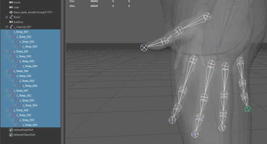
Figure 262: Rig Creation 9
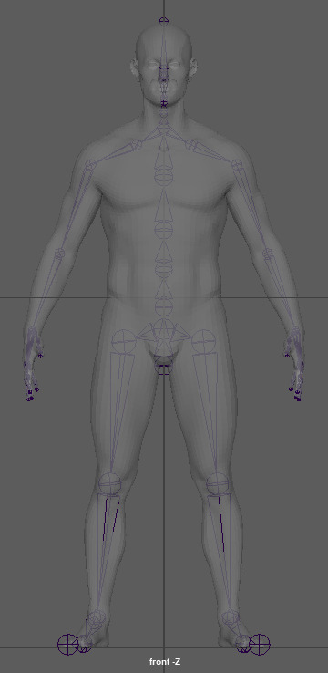
Figure 263: Rig Creation 10
Using the techniques that I had learn’t through creating the bones for a character I then proceeded to replicate the process for my own personal character, most of the rig is similar to the one created during the session, however, some elements were removed due to the overall visual style of my character, such as the jaw and chin bones for example, due to the character wearing a helmet it would not be possible to see the mouth moving correctly, in addition my character will not talk during the animation.
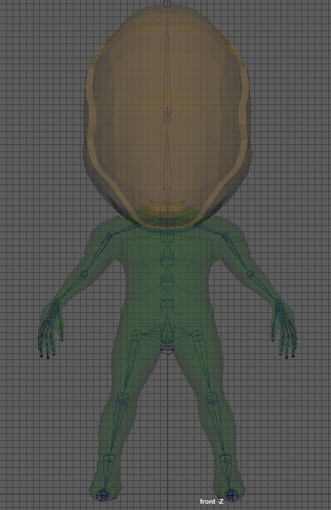
Figure 264: Rig Creation 11
0 notes