DFRobot supplies arduino, diy electronics, raspberry pi, arduino shield, arduino robot, arduino sensor, arduino kit, arduino robot kit, robot kit, intel edison, intel curie, intel joule, lattepanda , welcome to check.
Don't wanna be here? Send us removal request.
Text
How to Make a Matrix Watch by LED RGB Panel
Do you still remember the Clock on the Window that I made? At this time, I make a simple but special watch with same style. And below is the tutorial to make this Matrix Watch.
youtube
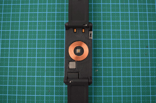
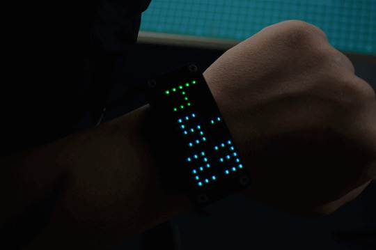
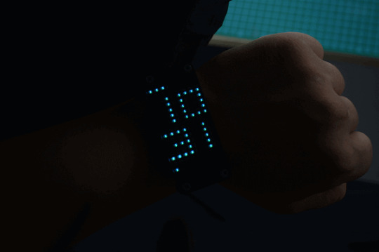
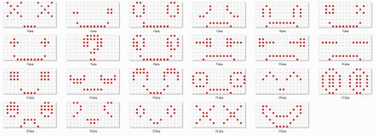
This Gravity: I2C 8x16 RGB LED Matrix Panel developed by DFRobot is the leading role. Usually, we use it as the face of robot and cars. It can show 7 colors, contains red, green, yellow, blue, purple, blue-green and white. And there are 23 different phiz. Of course, you can also diy other expressions.
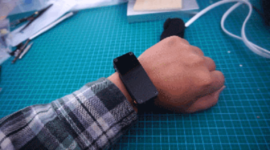
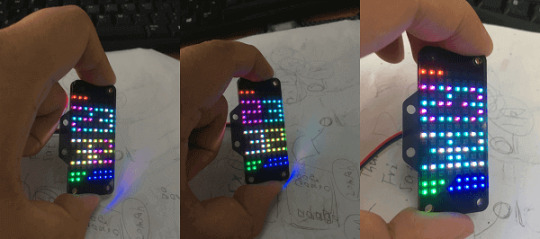
The first time I lighted it up, its beauty and clarity captured my heart, totally. Take a close look, it reminds me of Orion Horsehead Nebula. Immediately, I decided to use this board to make a watch. I am pretty sure that it will make me happy once I can see it.

When designing its surface, taking advantage of its multi-colors, I want to show candy colors.
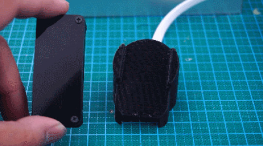
1.Design IdeaWe all know beauties cost more, so does our beautiful displays. It consumes more power to present a wonderful show. While the small wearable device cannot power by large battery, so the battery power consumption is an unavoidable problem. Well, I just thought about taking advantage of touch sensor to wake up the watch screen. For main board, I select pro mini for its small size and multiple pins which can totally handle this task.When the watch wearing in hand, it stays in low power consumption mode, sleep. Once the touch sensor is touched by hand, the whole device will be awake via interrupt and show time. Here I add a wireless charging module. In sleep mode, once the interrupt is triggered by hand touch, the watch will show charging cartoon. See, looks cool!
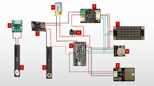
Material in Need1.
Gravity: I2C 8x16 RGB LED Matrix Panelx1
2.Gravity: Digital Capacitive Touch Sensor for Arduinox1
3.Wireless Charging Module 5V/300mAx1
4.DFRduino Pro Mini V1.3(8M3.3V328)x1
5.Gravity: I2C 3.7V Li Battery Fuel Gaugex1
6.DS3231 Clock Module x1
7.3.7v Lithium Battery Charging Board x1
8.3.7v Lithium Battery(30mah) x1
9.Micro USB Transfer Board x1
10.Dial Switch x1
11.FTDI Basic Breakout 3.3/5V (Arduino Compatible)x1
12.3.5mm-4mm Self-tapping Screw x4
13.3mm Screw and Screw Nut x2
14.The Smallest Screw that I can find x1
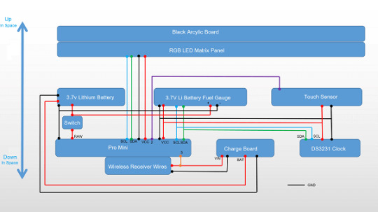
3.According to the connection diagram, here we go to soldering
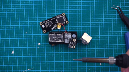
4.Assembly as follows
And we get this staff
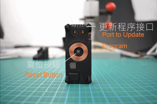
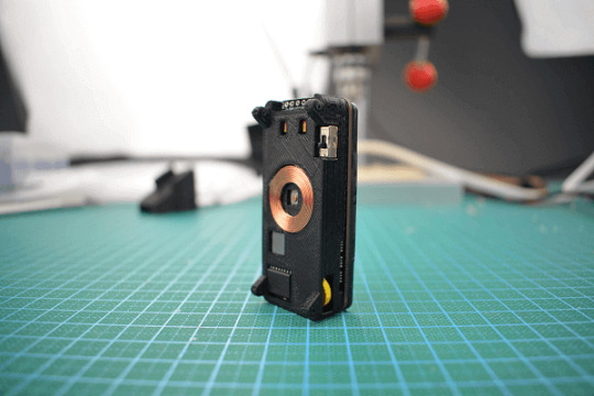

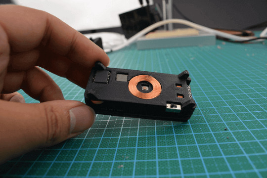
That’s all about how to make a matrix watch, thanks for your reading.
0 notes
Text
Smart Terrarium
Automated environment for reptiles to promote good husbandry and enable maximum lifespan for animals in captivity.

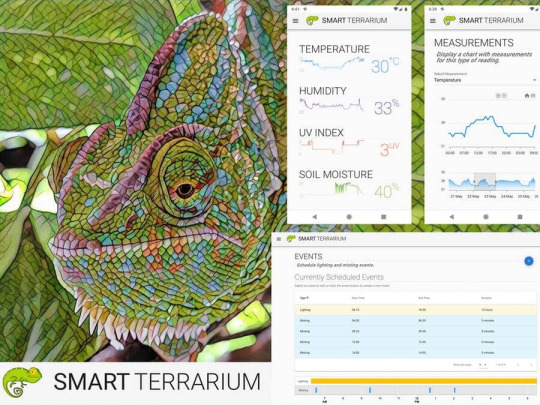
Things used in this project
Hardware components
Raspberry Pi 3 Model B×1
Arduino MKR1000 ×1
Arduino UNO & Genuino UNO ×1
DHT22 Temperature Sensor×1
Adafruit Waterproof DS18B20 Digital temperature sensor ×1
DFRobot Gravity: Analog UV Sensor (ML8511)×1
DFRobot Gravity: Analog Capacitive Soil Moisture Sensor- Corrosion Resistant×1
Ultrasonic Sensor - HC-SR04 (Generic) ×2Seeed Grove - 2-Channel SPDT Relay ×1
Hand tools and fabrication machines
3D Printer (generic)
Story
Intro
Smart Terrarium is the all in one system that provides the necessary information and automation to encourage a full and happy life for your reptiles. This system provides the user with the ability to monitor a variety of sensors in their animals habitat as well as control the lighting and misting system.
Backstory
This system was designed for my chameleon, Curie. She is a veiled chameleon and loves having her cage always kept in the optimal conditions. She is currently benefiting from the daily scheduled misting routines that the Smart Terrarium provides. This keeps her humidity in the appropriate range while also providing her with a nice place to cool off and get a drink.Another great part of having the Smart Terrarium is peace of mind. You no longer need to randomly check on the status of the mister bucket water level. You can always rely on the Smart Terrarium to notify you when you are running low. Also get notifications when the drain bucket is approaching maximum capacity.The most important part of this setup is the monitoring of the UV light. Chameleons require UV-B to produce Vitamin D. When a chameleon does not absorb enough calcium a chameleon can develop abnormalities in bone growth, rachitis, Metabolic Bone Disease (MBD) or just get very weak bones that are prone to breaking. The Smart Terrarium provides constant monitoring of UV light and can notify the user when the average UV index is below a certain threshold.
Hardware
This project uses a Raspberry Pi 3, an Arduino Uno, and a ArduinoMKR1000. The Raspberry Pi acts as our main system receiving readings from the Uno and MKR1000. The Pi also acts as a web server which delivers our app to the client when a user wants to monitor their system. They simply log in to a web page allowing them to interact with the Smart Terrarium from anywhere around the globe.

Raspberry Pi 3 A+
The MKR1000 is the main workhorse for getting sensor data and it sends its readings every second over wifi to the web server running on the Raspberry Pi. It has the following sensors connected to it:
(5) DS18B20 Digital Tempearture probes
(1) DHT22 Temperature & Humidity sensor
(1) UV sensor
(1)Soil Moisture sensor

Arduino MKR1000
The Arduino Uno is connected to the
Raspberry Pi via USB. It is used to monitor the water levels and also control the relays for the lights and misting pump. It has the following hardware connected:(2) HC-SR04 Ultrasonic Sensor
(2) Relays

Arduino Uno connected to 2 proximity sensors and 2 relays

Misting Bucket, Misting Pump, Drain Bucket with Proximity Sensor
Software
This system leverages the following open source software:Node.jsJohnny-fiveRethinkDBFirmataVue
Backend
The Raspberry Piis running an Express web server which collects readings from the sensors and saves them to a RethinkDB instance. The readings are being reported to the Pi every second so the user has access to the most current measurements.
The readings are saved every 5 minutes in Rethink DB for historical data.The Uno is running the PingFirmataSketch and using serial to expose the proximity sensors and relays to the Pi using Firmata protocol. The Pi leverages Johnny-five to allow the user to program in javascript.The MKR1000 is running a custom sketch using OneWire for the 5 temperature probes and then using analog inputs for the other sensors.
It posts the values to the Pi every second making sure the readings the user sees are fresh.
Frontend
The Raspberry Pi also serves up the front end portion of this app which leverages Vue.js. It allows the user to log in from anywhere having complete control over their pet's environment. The app works on any modern web browser so you can access it from a computer, tablet, or phone.The Smart Terrarium app allows the user to view the latests readings along with a sparkline graph of the previous day's historical data.The user can click through on any of the sensors
to view their history data.
The Measurements page shows a graph with the entire sensor history. The user can select a section of the bottom graph to display a zoomed in version in the graph above. This allows the user to inspect the historic data for any spikes or dips where the environment is out of the norm.The user has the ability to schedule events including lighting and misting events.
The Event page displays the currently scheduled events and allows the user to add, edit, and delete events. These events are used to automate the lighting and misting sessions which provides peace making sure you never forget.
The Controls page allows the user to manually override the scheduled lighting and misting events. The page displays the current status of each relay and allows the user to toggle them with a click of a button.The Admin page allow the user to enter information about themselves for contact purposes. This is for the email notifications on high/low water levels on misting system as well as notifications for when the daily average UV index gets too low. There is also a spot for the animals birthday so we can provide birthday notifications.
Screenshots
Home Page

Home Page

Historical Measurements

Historical Measurements

Historical Measurements
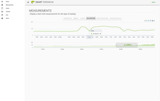
Historical Measurements (zoomed)>
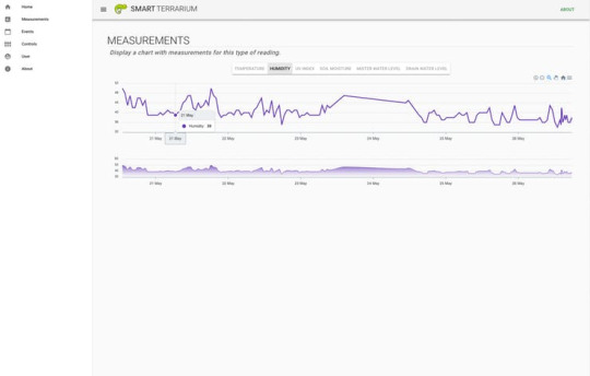
Historical Measurements
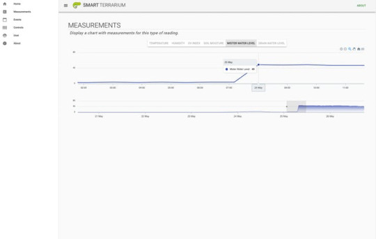
Historical Measurements (zoomed)
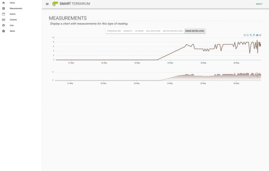
Historical Measurements
Events page for lighting and misting events.

Schedule Lighting and Misting Events
Controls page where the user can override the scheduled events. ��
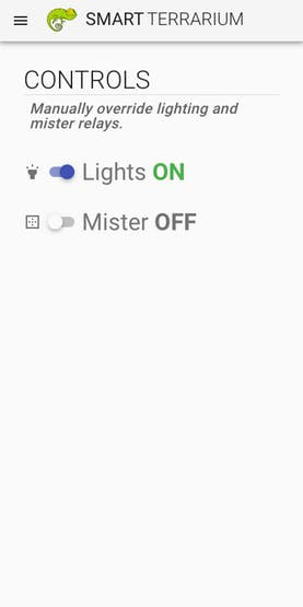
Misting and Lighting Overrides
Demo
Here is a demo of the overall system.
youtube
Demo of The Smart Terrarium
We hope you enjoyed our presentation of the Smart Terrarium and encourage any reptile owners to use this project to improve the lives of your pets.Thanks for your time and happy making!
Custom parts and enclosures
Plant Holder Brace
This provides extra support to the cage for hanging a plant.
Download Here
Mister Mount
This provides a nice clean installation of the misting head for the misting system.
Download Here
Schematics
Arduino Uno diagram
The Arduino Uno circuit used to control both relays for the lighting and misting system, as well as monitor the water levels on the misting bucket and drain.

Arduino MKR1000
This is really for the MKR1000 but tinkercad circuits didn't have it as a component. All pins are still correct.

Code
Ping Firmata
C#This is the version of firmata required for the
Proximity sensors
to function properly. Install this sketch on the Arduino Uno.
/* * Firmata is a generic protocol for communicating with microcontrollers * from software on a host computer. It is intended to work with * any host computer software package. * * To download a host software package, please clink on the following link * to open the download page in your default browser. * * http://firmata.org/wiki/Download */ /* Copyright (C) 2006-2008 Hans-Christoph Steiner. All rights reserved. Copyright (C) 2010-2011 Paul Stoffregen. All rights reserved. Copyright (C) 2009 Shigeru Kobayashi. All rights reserved. Copyright (C) 2009-2011 Jeff Hoefs. All rights reserved. Copyright (C) 2012 Julian Gaultier. All rights reserved. Copyright (C) 2015 Rick Waldron. All rights reserved. This library is free software; you can redistribute it and/or modify it under the terms of the GNU Lesser General Public License as published by the Free Software Foundation; either version 2.1 of the License, or (at your option) any later version. */ #include <Servo.h> #include <Wire.h> #include <Firmata.h> #define I2C_WRITE B00000000 #define I2C_READ B00001000 #define I2C_READ_CONTINUOUSLY B00010000 #define I2C_STOP_READING B00011000 #define I2C_READ_WRITE_MODE_MASK B00011000 #define I2C_10BIT_ADDRESS_MODE_MASK B00100000 #define MAX_QUERIES 8 #define MINIMUM_SAMPLING_INTERVAL 10 #define REGISTER_NOT_SPECIFIED -1 #define PING_READ 0x75 // PING_READ is for use with HCSR04 and similar "ultrasonic ping" components /*============================================================================== * GLOBAL VARIABLES *============================================================================*/ // analog inputs int analogInputsToReport = 0; // bitwise array to store pin reporting // digital input ports byte reportPINs[TOTAL_PORTS]; // 1 = report this port, 0 = silence byte previousPINs[TOTAL_PORTS]; // previous 8 bits sent // pins configuration byte pinConfig[TOTAL_PINS]; // configuration of every pin byte portConfigInputs[TOTAL_PORTS]; // each bit: 1 = pin in INPUT, 0 = anything else int pinState[TOTAL_PINS]; // any value that has been written // timer variables unsigned long currentMillis; // store the current value from millis() unsigned long previousMillis; // for comparison with currentMillis int samplingInterval = 19; // how often to run the main loop (in ms) // i2c data struct i2c_device_info { byte addr; byte reg; byte bytes; }; // for i2c read continuous more i2c_device_info query[MAX_QUERIES]; byte i2cRxData[32]; boolean isI2CEnabled = false; signed char queryIndex = -1; // default delay time between i2c read request and Wire.requestFrom() unsigned int i2cReadDelayTime = 0; Servo servos[MAX_SERVOS]; /*============================================================================== * FUNCTIONS *============================================================================*/ void readAndReportData(byte address, int theRegister, byte numBytes) { // allow I2C requests that don't require a register read // for example, some devices using an interrupt pin to signify new data available // do not always require the register read so upon interrupt you call Wire.requestFrom() if (theRegister != REGISTER_NOT_SPECIFIED) { Wire.beginTransmission(address); Wire.write((byte)theRegister); Wire.endTransmission(); delayMicroseconds(i2cReadDelayTime); // delay is necessary for some devices such as WiiNunchuck } else { theRegister = 0; // fill the register with a dummy value } Wire.requestFrom(address, numBytes); // all bytes are returned in requestFrom // check to be sure correct number of bytes were returned by slave if (numBytes == Wire.available()) { i2cRxData[0] = address; i2cRxData[1] = theRegister; for (int i = 0; i < numBytes; i++) { i2cRxData[2 + i] = Wire.read(); } } else { if (numBytes > Wire.available()) { Firmata.sendString("I2C Read Error: Too many bytes received"); } else { Firmata.sendString("I2C Read Error: Too few bytes received"); } } // send slave address, register and received bytes Firmata.sendSysex(SYSEX_I2C_REPLY, numBytes + 2, i2cRxData); } void outputPort(byte portNumber, byte portValue, byte forceSend) { // pins not configured as INPUT are cleared to zeros portValue = portValue & portConfigInputs[portNumber]; // only send if the value is different than previously sent if (forceSend || previousPINs[portNumber] != portValue) { Firmata.sendDigitalPort(portNumber, portValue); previousPINs[portNumber] = portValue; } } /* ----------------------------------------------------------------------------- * check all the active digital inputs for change of state, then add any events * to the Serial output queue using Serial.print() */ void checkDigitalInputs(void) { /* Using non-looping code allows constants to be given to readPort(). * The compiler will apply substantial optimizations if the inputs * to readPort() are compile-time constants. */ if (TOTAL_PORTS > 0 && reportPINs[0]) outputPort(0, readPort(0, portConfigInputs[0]), false); if (TOTAL_PORTS > 1 && reportPINs[1]) outputPort(1, readPort(1, portConfigInputs[1]), false); if (TOTAL_PORTS > 2 && reportPINs[2]) outputPort(2, readPort(2, portConfigInputs[2]), false); if (TOTAL_PORTS > 3 && reportPINs[3]) outputPort(3, readPort(3, portConfigInputs[3]), false); if (TOTAL_PORTS > 4 && reportPINs[4]) outputPort(4, readPort(4, portConfigInputs[4]), false); if (TOTAL_PORTS > 5 && reportPINs[5]) outputPort(5, readPort(5, portConfigInputs[5]), false); if (TOTAL_PORTS > 6 && reportPINs[6]) outputPort(6, readPort(6, portConfigInputs[6]), false); if (TOTAL_PORTS > 7 && reportPINs[7]) outputPort(7, readPort(7, portConfigInputs[7]), false); if (TOTAL_PORTS > 8 && reportPINs[8]) outputPort(8, readPort(8, portConfigInputs[8]), false); if (TOTAL_PORTS > 9 && reportPINs[9]) outputPort(9, readPort(9, portConfigInputs[9]), false); if (TOTAL_PORTS > 10 && reportPINs[10]) outputPort(10, readPort(10, portConfigInputs[10]), false); if (TOTAL_PORTS > 11 && reportPINs[11]) outputPort(11, readPort(11, portConfigInputs[11]), false); if (TOTAL_PORTS > 12 && reportPINs[12]) outputPort(12, readPort(12, portConfigInputs[12]), false); if (TOTAL_PORTS > 13 && reportPINs[13]) outputPort(13, readPort(13, portConfigInputs[13]), false); if (TOTAL_PORTS > 14 && reportPINs[14]) outputPort(14, readPort(14, portConfigInputs[14]), false); if (TOTAL_PORTS > 15 && reportPINs[15]) outputPort(15, readPort(15, portConfigInputs[15]), false); } // ----------------------------------------------------------------------------- /* sets the pin mode to the correct state and sets the relevant bits in the * two bit-arrays that track Digital I/O and PWM status */ void setPinModeCallback(byte pin, int mode) { if (pinConfig[pin] == I2C && isI2CEnabled && mode != I2C) { // disable i2c so pins can be used for other functions // the following if statements should reconfigure the pins properly disableI2CPins(); } if (IS_PIN_SERVO(pin) && mode != SERVO && servos[PIN_TO_SERVO(pin)].attached()) { servos[PIN_TO_SERVO(pin)].detach(); } if (IS_PIN_ANALOG(pin)) { reportAnalogCallback(PIN_TO_ANALOG(pin), mode == ANALOG ? 1 : 0); // turn on/off reporting } if (IS_PIN_DIGITAL(pin)) { if (mode == INPUT) { portConfigInputs[pin / 8] |= (1 << (pin & 7)); } else { portConfigInputs[pin / 8] &= ~(1 << (pin & 7)); } } pinState[pin] = 0; switch (mode) { case ANALOG: if (IS_PIN_ANALOG(pin)) { if (IS_PIN_DIGITAL(pin)) { pinMode(PIN_TO_DIGITAL(pin), INPUT); // disable output driver digitalWrite(PIN_TO_DIGITAL(pin), LOW); // disable internal pull-ups } pinConfig[pin] = ANALOG; } break; case INPUT: if (IS_PIN_DIGITAL(pin)) { pinMode(PIN_TO_DIGITAL(pin), INPUT); // disable output driver digitalWrite(PIN_TO_DIGITAL(pin), LOW); // disable internal pull-ups pinConfig[pin] = INPUT; } break; case OUTPUT: if (IS_PIN_DIGITAL(pin)) { digitalWrite(PIN_TO_DIGITAL(pin), LOW); // disable PWM pinMode(PIN_TO_DIGITAL(pin), OUTPUT); pinConfig[pin] = OUTPUT; } break; case PWM: if (IS_PIN_PWM(pin)) { pinMode(PIN_TO_PWM(pin), OUTPUT); analogWrite(PIN_TO_PWM(pin), 0); pinConfig[pin] = PWM; } break; case SERVO: if (IS_PIN_SERVO(pin)) { pinConfig[pin] = SERVO; if (!servos[PIN_TO_SERVO(pin)].attached()) { servos[PIN_TO_SERVO(pin)].attach(PIN_TO_DIGITAL(pin)); } } break; case I2C: if (IS_PIN_I2C(pin)) { // mark the pin as i2c // the user must call I2C_CONFIG to enable I2C for a device pinConfig[pin] = I2C; } break; default: Firmata.sendString("Unknown pin mode"); // TODO: put error msgs in EEPROM } // TODO: save status to EEPROM here, if changed } void analogWriteCallback(byte pin, int value) { if (pin < TOTAL_PINS) { switch (pinConfig[pin]) { case SERVO: if (IS_PIN_SERVO(pin)) servos[PIN_TO_SERVO(pin)].write(value); pinState[pin] = value; break; case PWM: if (IS_PIN_PWM(pin)) analogWrite(PIN_TO_PWM(pin), value); pinState[pin] = value; break; } } } void digitalWriteCallback(byte port, int value) { byte pin, lastPin, mask = 1, pinWriteMask = 0; if (port < TOTAL_PORTS) { // create a mask of the pins on this port that are writable. lastPin = port * 8 + 8; if (lastPin > TOTAL_PINS) lastPin = TOTAL_PINS; for (pin = port * 8; pin < lastPin; pin++) { // do not disturb non-digital pins (eg, Rx & Tx) if (IS_PIN_DIGITAL(pin)) { // only write to OUTPUT and INPUT (enables pullup) // do not touch pins in PWM, ANALOG, SERVO or other modes if (pinConfig[pin] == OUTPUT || pinConfig[pin] == INPUT) { pinWriteMask |= mask; pinState[pin] = ((byte)value & mask) ? 1 : 0; } } mask = mask << 1; } writePort(port, (byte)value, pinWriteMask); } } // ----------------------------------------------------------------------------- /* sets bits in a bit array (int) to toggle the reporting of the analogIns */ //void FirmataClass::setAnalogPinReporting(byte pin, byte state) { //} void reportAnalogCallback(byte analogPin, int value) { if (analogPin < TOTAL_ANALOG_PINS) { if (value == 0) { analogInputsToReport = analogInputsToReport & ~(1 << analogPin); } else { analogInputsToReport = analogInputsToReport | (1 << analogPin); } } // TODO: save status to EEPROM here, if changed } void reportDigitalCallback(byte port, int value) { if (port < TOTAL_PORTS) { reportPINs[port] = (byte)value; } // do not disable analog reporting on these 8 pins, to allow some // pins used for digital, others analog. Instead, allow both types // of reporting to be enabled, but check if the pin is configured // as analog when sampling the analog inputs. Likewise, while // scanning digital pins, portConfigInputs will mask off values from any // pins configured as analog } /*============================================================================== * SYSEX-BASED commands *============================================================================*/ void sysexCallback(byte command, byte argc, byte *argv) { byte mode; byte slaveAddress; byte slaveRegister; byte data; unsigned int delayTime; switch (command) { case I2C_REQUEST: mode = argv[1] & I2C_READ_WRITE_MODE_MASK; if (argv[1] & I2C_10BIT_ADDRESS_MODE_MASK) { Firmata.sendString("10-bit addressing not supported"); return; } else { slaveAddress = argv[0]; } switch (mode) { case I2C_WRITE: Wire.beginTransmission(slaveAddress); for (byte i = 2; i < argc; i += 2) { data = argv[i] + (argv[i + 1] << 7); Wire.write((byte)data); } Wire.endTransmission(); delayMicroseconds(70); break; case I2C_READ: case I2C_READ_CONTINUOUSLY: if (argc == 6) { // a slave register is specified slaveRegister = argv[2] + (argv[3] << 7); data = argv[4] + (argv[5] << 7); // bytes to read } else { // a slave register is NOT specified slaveRegister = (int)REGISTER_NOT_SPECIFIED; data = argv[2] + (argv[3] << 7); // bytes to read } if (mode == I2C_READ) { readAndReportData(slaveAddress, slaveRegister, data); } else { if ((queryIndex + 1) >= MAX_QUERIES) { Firmata.sendString("too many queries"); break; } queryIndex++; query[queryIndex].addr = slaveAddress; query[queryIndex].reg = slaveRegister; query[queryIndex].bytes = data; } break; case I2C_STOP_READING: byte queryIndexToSkip; // if read continuous mode is enabled for only 1 i2c device, disable // read continuous reporting for that device if (queryIndex <= 0) { queryIndex = -1; } else { // if read continuous mode is enabled for multiple devices, // determine which device to stop reading and remove it's data from // the array, shifiting other array data to fill the space for (byte i = 0; i < queryIndex + 1; i++) { if (query[i].addr == slaveAddress) { queryIndexToSkip = i; break; } } for (byte i = queryIndexToSkip; i < queryIndex + 1; i++) { if (i < MAX_QUERIES) { query[i].addr = query[i + 1].addr; query[i].reg = query[i + 1].reg; query[i].bytes = query[i + 1].bytes; } } queryIndex--; } break; default: break; } break; case I2C_CONFIG: delayTime = (argv[0] + (argv[1] << 7)); if (delayTime > 0) { i2cReadDelayTime = delayTime; } if (!isI2CEnabled) { enableI2CPins(); } break; case SERVO_CONFIG: if (argc > 4) { // these vars are here for clarity, they'll optimized away by the compiler byte pin = argv[0]; int minPulse = argv[1] + (argv[2] << 7); int maxPulse = argv[3] + (argv[4] << 7); if (IS_PIN_SERVO(pin)) { if (servos[PIN_TO_SERVO(pin)].attached()) { servos[PIN_TO_SERVO(pin)].detach(); } servos[PIN_TO_SERVO(pin)].attach(PIN_TO_DIGITAL(pin), minPulse, maxPulse); setPinModeCallback(pin, SERVO); } } break; case SAMPLING_INTERVAL: if (argc > 1) { samplingInterval = argv[0] + (argv[1] << 7); if (samplingInterval < MINIMUM_SAMPLING_INTERVAL) { samplingInterval = MINIMUM_SAMPLING_INTERVAL; } } else { //Firmata.sendString("Not enough data"); } break; case EXTENDED_ANALOG: if (argc > 1) { int val = argv[1]; if (argc > 2) { val |= (argv[2] << 7); } if (argc > 3) { val |= (argv[3] << 14); } analogWriteCallback(argv[0], val); } break; case CAPABILITY_QUERY: Serial.write(START_SYSEX); Serial.write(CAPABILITY_RESPONSE); for (byte pin = 0; pin < TOTAL_PINS; pin++) { if (IS_PIN_DIGITAL(pin)) { Serial.write((byte)INPUT); Serial.write(1); Serial.write((byte)OUTPUT); Serial.write(1); Serial.write((byte)PING_READ); Serial.write(1); } if (IS_PIN_ANALOG(pin)) { Serial.write(ANALOG); Serial.write(10); } if (IS_PIN_PWM(pin)) { Serial.write(PWM); Serial.write(8); } if (IS_PIN_SERVO(pin)) { Serial.write(SERVO); Serial.write(14); } if (IS_PIN_I2C(pin)) { Serial.write(I2C); Serial.write(1); // to do: determine appropriate value } Serial.write(127); } Serial.write(END_SYSEX); break; case PIN_STATE_QUERY: if (argc > 0) { byte pin = argv[0]; Serial.write(START_SYSEX); Serial.write(PIN_STATE_RESPONSE); Serial.write(pin); if (pin < TOTAL_PINS) { Serial.write((byte)pinConfig[pin]); Serial.write((byte)pinState[pin] & 0x7F); if (pinState[pin] & 0xFF80) { Serial.write((byte)(pinState[pin] >> 7) & 0x7F); } if (pinState[pin] & 0xC000) { Serial.write((byte)(pinState[pin] >> 14) & 0x7F); } } Serial.write(END_SYSEX); } break; case ANALOG_MAPPING_QUERY: Serial.write(START_SYSEX); Serial.write(ANALOG_MAPPING_RESPONSE); for (byte pin = 0; pin < TOTAL_PINS; pin++) { Serial.write(IS_PIN_ANALOG(pin) ? PIN_TO_ANALOG(pin) : 127); } Serial.write(END_SYSEX); break; case PING_READ: { byte pulseDurationArray[4] = { (argv[2] & 0x7F) | ((argv[3] & 0x7F) << 7), (argv[4] & 0x7F) | ((argv[5] & 0x7F) << 7), (argv[6] & 0x7F) | ((argv[7] & 0x7F) << 7), (argv[8] & 0x7F) | ((argv[9] & 0x7F) << 7)}; unsigned long pulseDuration = ((unsigned long)pulseDurationArray[0] << 24) + ((unsigned long)pulseDurationArray[1] << 16) + ((unsigned long)pulseDurationArray[2] << 8) + ((unsigned long)pulseDurationArray[3]); if (argv[1] == HIGH) { pinMode(argv[0], OUTPUT); digitalWrite(argv[0], LOW); delayMicroseconds(2); digitalWrite(argv[0], HIGH); delayMicroseconds(pulseDuration); digitalWrite(argv[0], LOW); } else { digitalWrite(argv[0], HIGH); delayMicroseconds(2); digitalWrite(argv[0], LOW); delayMicroseconds(pulseDuration); digitalWrite(argv[0], HIGH); } unsigned long duration; byte responseArray[5]; byte timeoutArray[4] = { (argv[10] & 0x7F) | ((argv[11] & 0x7F) << 7), (argv[12] & 0x7F) | ((argv[13] & 0x7F) << 7), (argv[14] & 0x7F) | ((argv[15] & 0x7F) << 7), (argv[16] & 0x7F) | ((argv[17] & 0x7F) << 7)}; unsigned long timeout = ((unsigned long)timeoutArray[0] << 24) + ((unsigned long)timeoutArray[1] << 16) + ((unsigned long)timeoutArray[2] << 8) + ((unsigned long)timeoutArray[3]); pinMode(argv[0], INPUT); duration = pulseIn(argv[0], argv[1], timeout); responseArray[0] = argv[0]; responseArray[1] = (((unsigned long)duration >> 24) & 0xFF); responseArray[2] = (((unsigned long)duration >> 16) & 0xFF); responseArray[3] = (((unsigned long)duration >> 8) & 0xFF); responseArray[4] = (((unsigned long)duration & 0xFF)); Firmata.sendSysex(PING_READ, 5, responseArray); break; } } } void enableI2CPins() { for (byte i = 0; i < TOTAL_PINS; i++) { if (IS_PIN_I2C(i)) { // mark pins as i2c so they are ignore in non i2c data requests setPinModeCallback(i, I2C); } } isI2CEnabled = true; // is there enough time before the first I2C request to call this here? Wire.begin(); } void disableI2CPins() { isI2CEnabled = false; queryIndex = -1; } void systemResetCallback() { if (isI2CEnabled) { disableI2CPins(); } for (byte i = 0; i < TOTAL_PORTS; i++) { reportPINs[i] = false; // by default, reporting off portConfigInputs[i] = 0; // until activated previousPINs[i] = 0; } // pins with analog capability default to analog input // otherwise, pins default to digital output for (byte i = 0; i < TOTAL_PINS; i++) { if (IS_PIN_ANALOG(i)) { // turns off pullup, configures everything setPinModeCallback(i, ANALOG); } else { // sets the output to 0, configures portConfigInputs setPinModeCallback(i, OUTPUT); } } // by default, do not report any analog inputs analogInputsToReport = 0; } void setup() { Firmata.setFirmwareVersion(FIRMATA_MAJOR_VERSION, FIRMATA_MINOR_VERSION); Firmata.attach(ANALOG_MESSAGE, analogWriteCallback); Firmata.attach(DIGITAL_MESSAGE, digitalWriteCallback); Firmata.attach(REPORT_ANALOG, reportAnalogCallback); Firmata.attach(REPORT_DIGITAL, reportDigitalCallback); Firmata.attach(SET_PIN_MODE, setPinModeCallback); Firmata.attach(START_SYSEX, sysexCallback); Firmata.attach(SYSTEM_RESET, systemResetCallback); Firmata.begin(57600); systemResetCallback(); // reset to default config } void loop() { byte pin, analogPin; /* DIGITALREAD - as fast as possible, check for changes and output them to the * FTDI buffer using Serial.print() */ checkDigitalInputs(); /* SERIALREAD - processing incoming messagse as soon as possible, while still * checking digital inputs. */ while (Firmata.available()) { Firmata.processInput(); } /* SEND FTDI WRITE BUFFER - make sure that the FTDI buffer doesn't go over * 60 bytes. use a timer to sending an event character every 4 ms to * trigger the buffer to dump. */ currentMillis = millis(); if (currentMillis - previousMillis > samplingInterval) { previousMillis += samplingInterval; /* ANALOGREAD - do all analogReads() at the configured sampling interval */ for (pin = 0; pin < TOTAL_PINS; pin++) { if (IS_PIN_ANALOG(pin) && pinConfig[pin] == ANALOG) { analogPin = PIN_TO_ANALOG(pin); if (analogInputsToReport & (1 << analogPin)) { Firmata.sendAnalog(analogPin, analogRead(analogPin)); } } } // report i2c data for all device with read continuous mode enabled if (queryIndex > -1) { for (byte i = 0; i < queryIndex + 1; i++) { readAndReportData(query[i].addr, query[i].reg, query[i].bytes); } } } }
MKR1000 Sketch
C#This sketch sends the majority of sensor readings to the app running on the Raspberry Pi. Make sure to update the Wifi SSID and Password before uploading.
#include <OneWire.h> #include <DallasTemperature.h> #include <ArduinoHttpClient.h> #include <WiFi101.h> #include <SimpleDHT.h> // Using Pin 5 of MKR1000 #define ONE_WIRE_BUS_PIN 5 // TODO: Move out ot separate file #define SECRET_SSID "SECRET_SSID" #define SECRET_PASS "SECRET_PASS" #define RIG_NAME "Gill" char ssid[] = SECRET_SSID; char pass[] = SECRET_PASS; // Setup a oneWire instance for temperature probes OneWire oneWire(ONE_WIRE_BUS_PIN); // Pass our oneWire reference to Dallas Temperature. DallasTemperature sensors(&oneWire); // probe_a: "28 FF 2F 9C B0 16 3 34" // probe_b: "28 FF 36 1E B1 16 4 4D" // probe_c: "28 FF 27 1E B1 16 4 FC" // probe_d: "28 FF 6A 74 B0 16 5 87" // probe_e: "28 FF E B5 B0 16 3 E2" // Define device addresses for each probe DeviceAddress Probe01 = {0x28, 0xFF, 0x2F, 0x9C, 0xB0, 0x16, 0x03, 0x34}; DeviceAddress Probe02 = {0x28, 0xFF, 0x36, 0x1E, 0xB1, 0x16, 0x04, 0x4D}; DeviceAddress Probe03 = {0x28, 0xFF, 0x27, 0x1E, 0xB1, 0x16, 0x04, 0xFC}; DeviceAddress Probe04 = {0x28, 0xFF, 0x6A, 0x74, 0xB0, 0x16, 0x05, 0x87}; DeviceAddress Probe05 = {0x28, 0xFF, 0x0E, 0xB5, 0xB0, 0x16, 0x03, 0xE2}; int uvSensor = A1; int uvIndex = 0; int pinDHT22 = A2; SimpleDHT22 dht22(pinDHT22); int soilSensor = A3; int soilMoisture = 0; char serverAddress[] = "192.168.86.127"; // raspberry pi address int port = 3030; WiFiClient wifi; HttpClient client = HttpClient(wifi, serverAddress, port); int status = WL_IDLE_STATUS; String response; int statusCode = 0; void setup() { // start serial port to show results Serial.begin(9600); delay(3000); pinMode(LED_BUILTIN, OUTPUT); while (status != WL_CONNECTED) { Serial.print("Attempting to connect to Network named: "); Serial.println(ssid); // print the network name (SSID); // Connect to WPA/WPA2 network: status = WiFi.begin(ssid, pass); } // print the SSID of the network you're attached to: Serial.print("SSID: "); Serial.println(WiFi.SSID()); // print your WiFi shield's IP address: IPAddress ip = WiFi.localIP(); Serial.print("IP Address: "); Serial.println(ip); Serial.print("Initializing Temperature Control Library Version "); Serial.println(DALLASTEMPLIBVERSION); // Initialize the Temperature measurement library sensors.begin(); // set the resolution to 10 bit (Can be 9 to 12 bits .. lower is faster) sensors.setResolution(Probe01, 9); sensors.setResolution(Probe02, 9); sensors.setResolution(Probe03, 9); sensors.setResolution(Probe04, 9); sensors.setResolution(Probe05, 9); } void loop() /****** LOOP: RUNS CONSTANTLY ******/ { Serial.println(); Serial.print("Total Probes: "); Serial.println(sensors.getDeviceCount()); // Command all devices on bus to read temperature sensors.requestTemperatures(); float probeA = sensors.getTempC(Probe01); float probeB = sensors.getTempC(Probe02); float probeC = sensors.getTempC(Probe03); float probeD = sensors.getTempC(Probe04); float probeE = sensors.getTempC(Probe05); float moistureSensorValue = analogRead(soilSensor); soilMoisture = ((moistureSensorValue / 1024) - 1) * 100 * -1; float uvSensorValue = analogRead(uvSensor); uvIndex = uvSensorValue / 1024 * 3.3 / 0.1; Serial.print("Rig Name: "); Serial.println(String(RIG_NAME)); Serial.print("ProbeA: "); printTemperature(Probe01); Serial.println(); Serial.print("ProbeB: "); printTemperature(Probe02); Serial.println(); Serial.print("ProbeC: "); printTemperature(Probe03); Serial.println(); Serial.print("ProbeD: "); printTemperature(Probe04); Serial.println(); Serial.print("ProbeE: "); printTemperature(Probe05); Serial.println(); Serial.print("soilMoisture: "); Serial.print(soilMoisture); Serial.println(); Serial.print("uvIndex: "); Serial.print(uvIndex); Serial.println(); byte temperature = 0; byte humidity = 0; int err = SimpleDHTErrSuccess; if ((err = dht22.read(&temperature, &humidity, NULL)) != SimpleDHTErrSuccess) { Serial.print("Read DHT22 failed, err="); Serial.println(err); } else { Serial.print("DHT22: "); Serial.print((int)temperature); Serial.print(" *C, "); Serial.print((int)humidity); Serial.println(" RH%"); } String postURL = String("POST readings to " + String(serverAddress) + ':' + String(port)); Serial.println(postURL); String contentType = "application/x-www-form-urlencoded"; String postData = String( "probeA=" + String(probeA) + "&probeB=" + String(probeB) + "&probeC=" + String(probeC) + "&probeD=" + String(probeD) + "&probeE=" + String(probeE) + "&rig_name=" + String(RIG_NAME) + "&uvIndex=" + String(uvIndex) + "&soilMoisture=" + String(soilMoisture) + "&humidity=" + String(humidity) + "&temperature=" + String(temperature)); digitalWrite(LED_BUILTIN, HIGH); client.post("/temperatures", contentType, postData); // read the status code and body of the response statusCode = client.responseStatusCode(); response = client.responseBody(); Serial.print("Status code: "); Serial.println(statusCode); Serial.print("Response: "); Serial.println(response); digitalWrite(LED_BUILTIN, LOW); delay(100); digitalWrite(LED_BUILTIN, HIGH); delay(100); digitalWrite(LED_BUILTIN, LOW); delay(100); digitalWrite(LED_BUILTIN, HIGH); delay(100); digitalWrite(LED_BUILTIN, LOW); delay(1000); } // print temperature for device adress void printTemperature(DeviceAddress deviceAddress) { float tempC = sensors.getTempC(deviceAddress); if (tempC == -127.00) { Serial.print("Error getting temperature "); } else { Serial.print(tempC, 1); Serial.print(" C"); // Serial.print(" F: "); // Serial.print(DallasTemperature::toFahrenheit(tempC)); } }
SmartTerrariumClient
This is the Client portion of Smart Terrarium built using Vue.js.
ryanjgill / smart-terrarium-client
Client for Smart Terrarium —
Read More
Latest commit to the master branch on 5-27-2019
Download as zip
SmartTerrariumApp
Smart Terrarium App for receiving data, controlling hardware, and running the Smart Terrarium Client. This repo also contains the sketch for the MKR1000.
ryanjgill / smart-terrarium-app
Smart Terrarium App for receiving data, controlling hardware, and running the Smart Terrarium Client — Read More
Latest commit to the master branch on 5-31-2019
Download as zip
(This article copied from hackster.io Author: Ryan Gill)
0 notes
Text
Weather Station With Data Logging
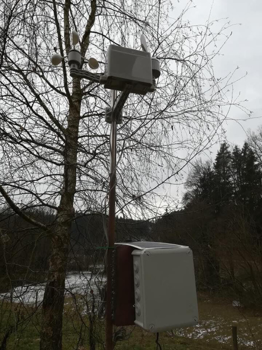
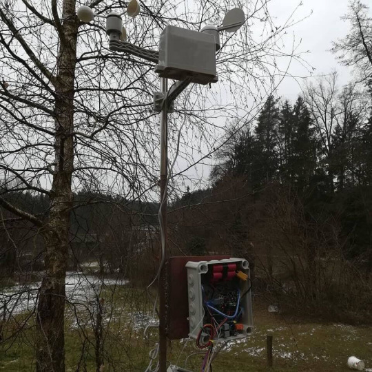
This weather station project is still in the making. This is only first part. Upgrades will be uploaded in next one or two months.
Step 1: Materials
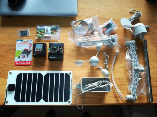
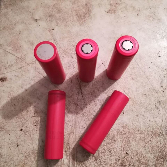
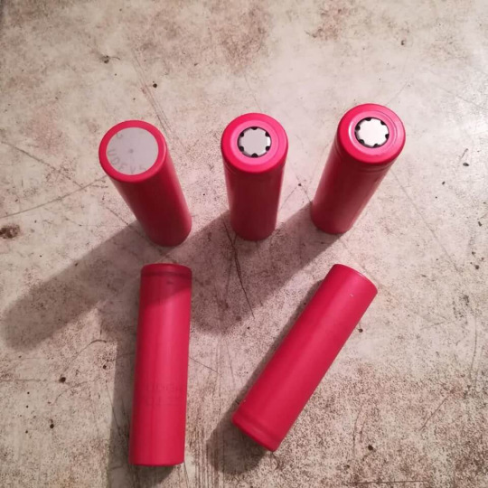
Nearly all needed materials for this project can be bought on online store: DFRobot For this project we will need:-Weather station kit -Arduino SD card modul -SD card -Solar power manager -5V 1A Solar panel -Some nylon cable ties -Mounting kit -LCD display -Breadboard -Li- ion batteries (I used Sanyo 3.7V 2250mAh batteries) -Waterproof plastic junction box -Some wires -Resistors (2x 10kOhm)
Step 2: Modules
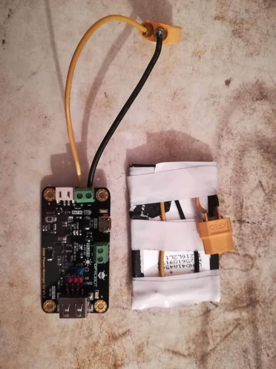
For this project I used two different modules.Solar power manager This module can be powered with two different supplys, 3.7V battery, 4.5V - 6V solar panel or USB cable. It has two diffrent outputs. 5V USB output which can be used for supplying Arduino or some other controller and 5V pins for powering different modules and sensors.Specifications: Solar Input Voltage (SOLAR IN): 4.5V~6V Battery Input (BAT IN): 3.7V Single cell Li-polymer/Li-ion BatteryCharge Current(USB/SOLAR IN): 900mA Max trickle charging, constant current, constant voltage three phases charging Charging Cutoff Voltage (USB/SOLAR IN): 4.2V±1% Regulated Power Supply: 5V 1A Regulated Power Supply Efficiency (3.7V BAT IN): 86%@50%Load USB/Solar Charge Efficiency: 73%@3.7V 900mA BAT INSD module This module is fully compatible with Arduino. It allows you to add mass storage and data logging to your project. I used it for collecting data from weather station with 16GB SD card.Specifications: Break out board for standard SD card and Micro SD (TF) card Contains a switch to select the flash card slot Sits directly on a Arduino Also be used with other microcontrollers
Step 3: Weather Station Kit
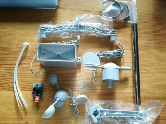
The main component for this project is weather station kit. It is powered by 5V from Arduino or you can also use external 5V supply. It has 4 pins (5V, GND, TX, RX). TXD data port uses 9600bps.Weather station kit consist of: Anemometer Wind vane Rain bucket Sensor Board Stainless steel studdle (30CM)(11.81") Component package It can be used to measure: Wind speed Wind direction Amount of rainfallIt has build in humidity and temperature sensor which can also measure barometric pressure. Anemometer can measure wind speed up to 25 m/s. Wind direction is displayed in degrees. More info about this kit and sample code can be found on: DFRobot wiki
Step 4: How to Assemble Weather Station Kit
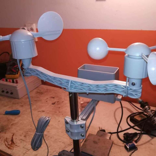

The assembly of this kit is quite easy but for more info about assembly watch a tutorial on how to assemble this kit.Tutorial: How to assemble weather station kit
youtube
Step 5: Supply and Housing
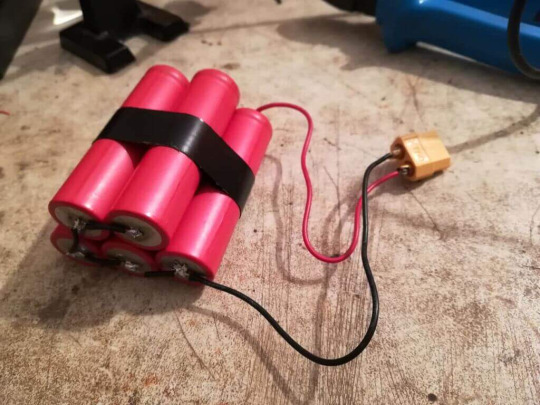
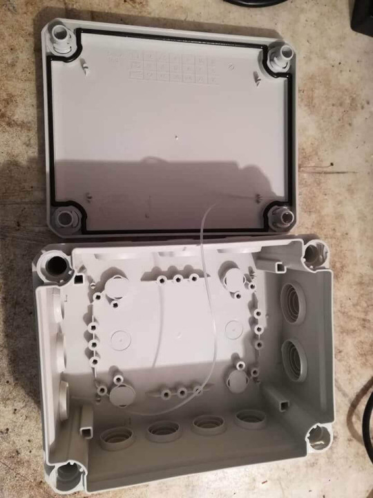

Battery: For this project I used 3.7V li-ion batteries. I made battery pack from 5x of this batteries. Every battery has about 2250 mAh, so a pack of 5x gives about 11250 mAh when connected in parallel. Connection: As I mentioned I connected batteries in parallel, because in parallel you keep the original voltage but gain greater battery capacity. For example: If you have two 3.7V 2000 mAh battery and you connect it in parallel you will get 3.7V and 4000 mAh. If you want to achive greater voltage then you need to connect them in series. For example: If you connect two 3.7V 2000 mAh battery in series you will get 7,4V and 2000 mAh. Solar panel:I used 5V 1A solar panel. This panel has about max 5W of output power. Output voltage goes up to 6V. When I tested panel in cloudy weather its output voltage was about 5.8-5.9V. But if you want to fully supply this weather station with solar energy you need to add 1 or 2 solar panels and lead-acid battery or something else to store energy and to supply station when there is no sun.HOUSING: It doesn't seems but housing is one of the most important parts of this system, because it protects vital components from outside elements. So I choose waterproof plastic junction box. It has just large enough to fit all the components inside. It is about 19x15 cm.
Step 6: Wiring and Code
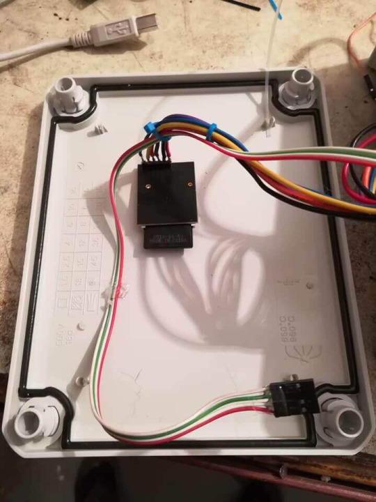
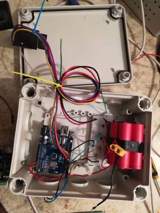

Arduino:All the components are connected with Arduino.
-SD module:
5V -> 5V
GND -> GND
MOSI -> digital pin 9
MISO -> digital pin 11
SCK -> digital pin 12
SS -> digital pin 10
Weather station board:
5V -> 5V
GND -> GND
TX -> RX on Arduino
RX -> TX on ArduinoBattery pack is connected directly to power manager (3.7V battery input). I also made connection from battery to analog pin A0 on Arduino for voltage monitoring.
Solar panel is connected directy to this modul (solar input). Solar panel is also connected to voltage divider. Voltage divider output is connected to analog pin A1 on Arduino.I also made connection so that you can connect LCD display on it to check the voltage. So LCD is connected to 5V, GND and SDA from LCD goes to SDA on Arduino and the same with SCK pin.Arduino is connected to power manager module with USB cable.CODE:Code for this weather station can found on DFRobot wiki. I also attached my code with all the upgrades.
-If you want to get the right wind direction for your position, you need to manualy change degress values in the program.
So all the data is stored into txt file named test. You can rename this file if you want. I writes all the possible values from weather station and it also writes in battery voltage and solar voltage. So that you can see how is the consumption of battery.
Step 7: Measuring Voltage and Testing
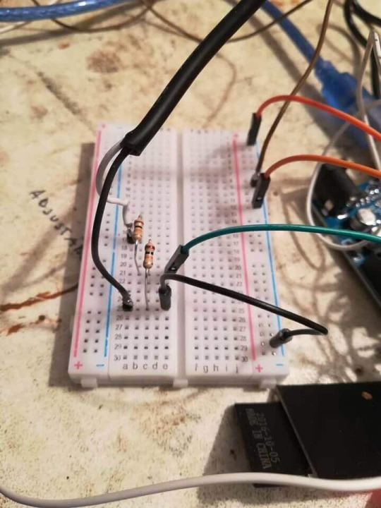
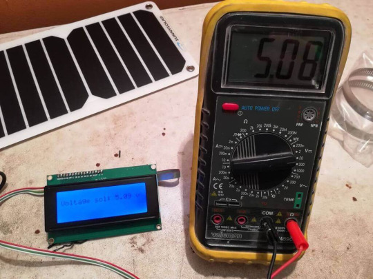

I needed to make voltage monitoring on battery and solar panel for my project.For monitoring the voltage on battery I used analog pin. I connected + from battery to analog pin A0 and - from battery to GND on Arduino. In programm I used "analogRead" function and "lcd.print()" for displaying voltage value on LCD. Third picture shows voltage on battery. I measured it with Arduino and also with multimeter so that I could compare the value. Difference between this two values was about 0.04V.Because output voltage from solar panel is greater than 5V I neede to make voltage divider. Analog input can take maximum of 5V input voltage. I made it with two 10kOhm resistor. Use of two resistor with equal value, divides voltage exactly to half. So if you connect 5V, output voltage will be about 2.5V. This voltage divider is on the first picture. Difference between voltage value on LCD and on multimeter was about 0.1-0.2V
Equasion for voltage divider output is: Vout=(Vcc*R2)/R1+R2Testing
When I connected everything together and packed all the components into housing I needed to make outside test. So I took out weather station outside to see how it will work in real outside conditions. The main purpose of this test was to see how will batteries work or how much it will discharge during this test. While testing outside temperature was about 1°C outside and about 4°C inside the housing.Battery voltage dropped from 3.58 to about 3.47 in five hours.
Code
#include <SD.h> //SD #include <SPI.h> //SD File myFile; //SD int pinCS = 10; //////////// //LCD #include <Wire.h> #include <LiquidCrystal_I2C.h> #define BACKLIGHT_PIN 3 LiquidCrystal_I2C lcd(0x20, 2, 1, 0, 4, 5, 6, 7, 3, POSITIVE); /////////// int sensorPin = A0; //battery voltage pin int sensorValue = 0; /////////////////// int sensorPin_solar = A1; //solar panel voltage pin int sensorValue_solar = 0; //////////////// char databuffer[35]; double temp; void getBuffer() //Get weather status data { int index; for (index = 0;index < 35;index ++) { if(Serial.available()) { databuffer[index] = Serial.read(); if (databuffer[0] != 'c') { index = -1; } } else { index --; } } } int transCharToInt(char *_buffer,int _start,int _stop) //char to int) { int _index; int result = 0; int num = _stop - _start + 1; int _temp[num]; for (_index = _start;_index <= _stop;_index ++) { _temp[_index - _start] = _buffer[_index] - '0'; result = 10*result + _temp[_index - _start]; } return result; } int WindDirection() //Wind Direction { return transCharToInt(databuffer,1,3); } float WindSpeedAverage() //air Speed (1 minute) { temp = 0.44704 * transCharToInt(databuffer,5,7); return temp; } float WindSpeedMax() //Max air speed (5 minutes) { temp = 0.44704 * transCharToInt(databuffer,9,11); return temp; } float Temperature() //Temperature ("C") { temp = (transCharToInt(databuffer,13,15) - 32.00) * 5.00 / 9.00; return temp; } float RainfallOneHour() //Rainfall (1 hour) { temp = transCharToInt(databuffer,17,19) * 25.40 * 0.01; return temp; } float RainfallOneDay() //Rainfall (24 hours) { temp = transCharToInt(databuffer,21,23) * 25.40 * 0.01; return temp; } int Humidity() //Humidity { return transCharToInt(databuffer,25,26); } float BarPressure() //Barometric Pressure { temp = transCharToInt(databuffer,28,32); return temp / 10.00; } void setup() { lcd.begin (20,4); lcd.setBacklightPin(BACKLIGHT_PIN,POSITIVE); lcd.setBacklight(HIGH); lcd.home (); ////////// Serial.begin(9600); //////// pinMode(pinCS, OUTPUT); // SD Card Initialization if (SD.begin()) { Serial.println("SD card is ready to use."); } else { Serial.println("SD card initialization failed"); return; } ////////// } void loop() { ////////////////// sensorValue = analogRead(sensorPin); //Monitoring battery voltage float voltage = sensorValue*(5.0/1023.0); lcd.setCursor(0,3); //0,3 lcd.print("Voltage bat: "); lcd.print(voltage); lcd.print(" V"); ///////////////// sensorValue_solar = analogRead(sensorPin_solar); float voltage_solar = 2*sensorValue_solar*(5.0/1023.0)-0.07; Serial.println(voltage_solar); // lcd.setCursor(0,2); //This is example how to set your LCD commands // lcd.print("Voltage sol: "); // lcd.print(voltage_solar); // lcd.print(" v"); ///////////////////// getBuffer(); //Begin! /////// if(WindDirection()==0){ Serial.print("Wind Direction: "); Serial.print("SW"); Serial.println(" "); } if(WindDirection()==45){ Serial.print("Wind Direction: "); Serial.print(" W"); Serial.println(" "); } if(WindDirection()==90){ Serial.print("Wind Direction: "); Serial.print("NW"); Serial.println(" "); } if(WindDirection()==135){ Serial.print("Wind Direction: "); Serial.print(" N"); Serial.println(" "); } if(WindDirection()==180){ Serial.print("Wind Direction: "); Serial.print("NE"); Serial.println(" "); } if(WindDirection()==225){ Serial.print("Wind Direction: "); Serial.print(" E"); Serial.println(" "); } if(WindDirection()==270){ Serial.print("Wind Direction: "); Serial.print("SE"); Serial.println(" "); } if(WindDirection()==315){ Serial.print("Wind Direction: "); Serial.print(" S"); Serial.println(" "); } // Serial.print("Wind Direction: "); //Serial.print(WindDirection()); // Serial.println(" "); Serial.print("Average Wind Speed (One Minute): "); Serial.print(WindSpeedAverage()); Serial.println("m/s "); Serial.print("Max Wind Speed (Five Minutes): "); Serial.print(WindSpeedMax()); Serial.println("m/s"); // lcd.setCursor(0,0); // lcd.print("Max Speed"); // lcd.print(" "); //lcd.print(WindSpeedMax()); // lcd.print(" "); // lcd.print("m/s"); Serial.print("Rain Fall (One Hour): "); Serial.print(RainfallOneHour()); Serial.println("mm "); Serial.print("Rain Fall (24 Hour): "); Serial.print(RainfallOneDay()); Serial.println("mm"); Serial.print("Temperature: "); Serial.print(Temperature()); Serial.println("C "); // lcd.setCursor(0,2); // lcd.print("Temperature: "); // lcd.print(Temperature()); // lcd.print("C "); Serial.print("Humidity: "); Serial.print(Humidity()); Serial.println("% "); Serial.print("Barometric Pressure: "); Serial.print(BarPressure()); Serial.println("hPa"); Serial.println(""); Serial.println(""); //// myFile = SD.open("test.txt", FILE_WRITE); if (myFile) { if(WindDirection()==0){ myFile.print("Wind Direction: "); myFile.print("SW"); myFile.println(" "); } if(WindDirection()==45){ myFile.print("Wind Direction: "); myFile.print(" W"); myFile.println(" "); } if(WindDirection()==90){ myFile.print("Wind Direction: "); myFile.print("NW"); myFile.println(" "); } if(WindDirection()==135){ myFile.print("Wind Direction: "); myFile.print(" N"); myFile.println(" "); } if(WindDirection()==180){ myFile.print("Wind Direction: "); myFile.print("NE"); myFile.println(" "); } if(WindDirection()==225){ myFile.print("Wind Direction: "); myFile.print(" E"); myFile.println(" "); } if(WindDirection()==270){ myFile.print("Wind Direction: "); myFile.print("SE"); myFile.println(" "); } if(WindDirection()==315){ myFile.print("Wind Direction: "); myFile.print(" S"); myFile.println(" "); } // myFile.print("Wind Direction: "); // myFile.print(WindDirection()); // myFile.println(" "); myFile.print("Average Wind Speed (One Minute): "); myFile.print(WindSpeedAverage()); myFile.println("m/s "); myFile.print("Max Wind Speed (Five Minutes): "); myFile.print(WindSpeedMax()); myFile.println("m/s"); myFile.print("Rain Fall (One Hour): "); myFile.print(RainfallOneHour()); myFile.println("mm "); myFile.print("Rain Fall (24 Hour): "); myFile.print(RainfallOneDay()); myFile.println("mm"); myFile.print("Temperature: "); myFile.print(Temperature()); myFile.println("C "); myFile.print("Humidity: "); myFile.print(Humidity()); myFile.println("% "); myFile.print("Barometric Pressure: "); myFile.print(BarPressure()); myFile.println("hPa"); myFile.println(""); myFile.println(""); myFile.print("Voltage bat: "); myFile.print(voltage); myFile.println(" V"); myFile.print("Voltage sol: "); myFile.print(voltage_solar); myFile.println(" V"); myFile.close(); // close the file } // if the file didn't open, print an error: else { Serial.println("error opening test.txt"); } delay(100); }
0 notes
Text
Weather Station With Wireless Data Transmitting
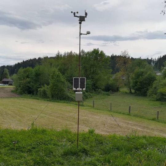
This project is the upgrade of my previous project - Weather station with data logging.
Previous project can be seen here - Weather station with data logging
So let's begin
Step 1: What Is New?
I have made some upgrades and improvements to my previous project - Weather station with data logging.I added wireless data transmitting from weather station to the receiver which is located indoor.Also SD card module was removed and replaced with Arduino Uno interface shield.Main reason for that replacement was the space usage, interface shield is fully compatible with Arduino Uno so you dont need to use wires for connection.Weather station stand was redesigned. Previous weather station stand was too low and very unstable , so I made new taller and more stable weather station stand.
I also added new holder for the housing which is mounted directly to the weather station stand.
Additional solar panel was added for supplying.
Step 2: Materials
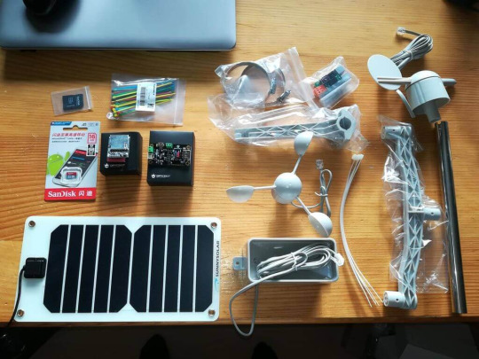
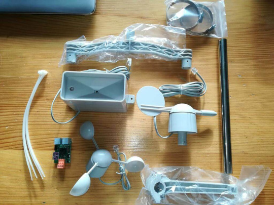
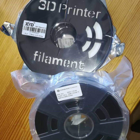
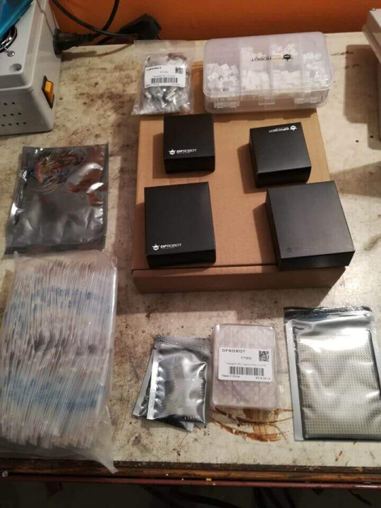
Nearly all needed materials for this project can be bought on online store: DFRobot For this project we will need:
-Weather station kit
-Arduino Uno
-Arduino Nano
-RF 433 MHz module for Arduino (receiver and transmitter)
-Protoboard
-SD card
-Solar power manager
-5V 1A Solar panel 2x
-Arduino Uno interface shield
-Some nylon cable ties
-Mounting kit
-LCD display
-Breadboard
-Li- ion batteries (I used Sanyo 3.7V 2250mAh batteries)
-Waterproof plastic junction box
-Some wiresFor weather station stand you will need:-about 3.4m long steel pipe or you can also use steel profile.
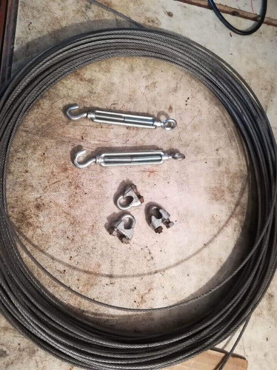
-wire rope (about 4m)
-wire rope clamp 8x
-Stainless Steel Turnbuckles 2x
-fi10 steel rod (about 50cm)
-Steel lifting eye nut 4x
You will also need some tools:
-soldering iron
-screwdrivers
-pliers
-drill
-welding machine
-angle grinder
-wire brush
Step 3: Summary
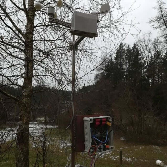
As I said this Instructable is the upgrade of my previous Instructable about weather station.So if you want to know how to assemble weather station kit which is needed for this project you can take a look here:
How to Assemble Weather Station Kit
youtube
Also take a look at my previous instructable about this weather station.
Weather Station With Data Logging
Step 4: Weather Station Mounting Solution
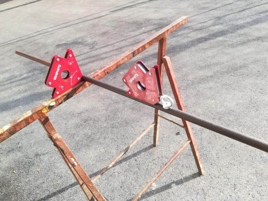
With weather station there also comes the question how to make the mounting stand that will endure outside elements.
I needed to make some reserch about the types and designes of weather station stand. After some reserches I decided to make stand with 3m long stell pipe. It is recommened that anemometer is on the highest point at about 10m(33ft), but because I have weather station kit which is All-In-One I choose the recommened height - about 3m(10ft).The main thing that I needed to consider is that, this stand must be modular and easy to assemble and disassemble so it can be carried to another location.
Assembly:I started with fi18 3.4m(11.15ft) long steel pipe. First I needed to remove the rust from the pipe so I coated it with rust remover acid.After 2 to 3 hours when the acid done its part, I started welding everything together. First I welded lifting eye nut on the opposite sides of steel pipe. I positioned it at the height of 2m from the ground, it can be also put higher, but not lower because then the upper part becomes unstable.Then I needed to make two "anchors", one for each side. For that I took two fi12 50cm(1.64ft) steel rods. On the top of each rod I welded one lifting eye nut and a small steel plate so you can step on it or hammer it into the ground. This can be viewed on picture ( napiš na kiri sliki)I needed to connect the "anchors" with the lifting eye on both sides of the stand, for that I used wire rope. First I used two about 1.7m(5.57ft) long pieces of wire rope, on side was directly attached to lifting eye nut with the wire rope clamp and the other side was attached to stainless steel turnbuckles. Stainless Steel Turnbuckles is used for tightening the wire rope.For mounting plastic junction box to the stand I 3D printed handhold. More about this can be viewed in step 5
At the end I painted every steel part with the primar color (two layers). Onto this color you can then lay every color you want.
Step 5: 3D Printed Parts
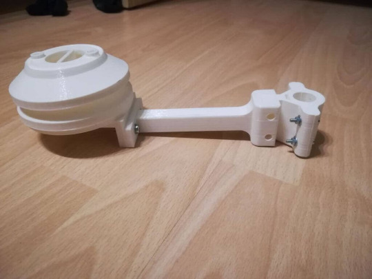
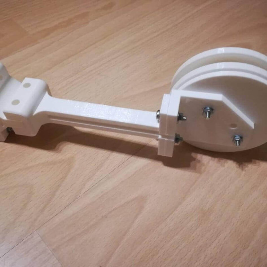
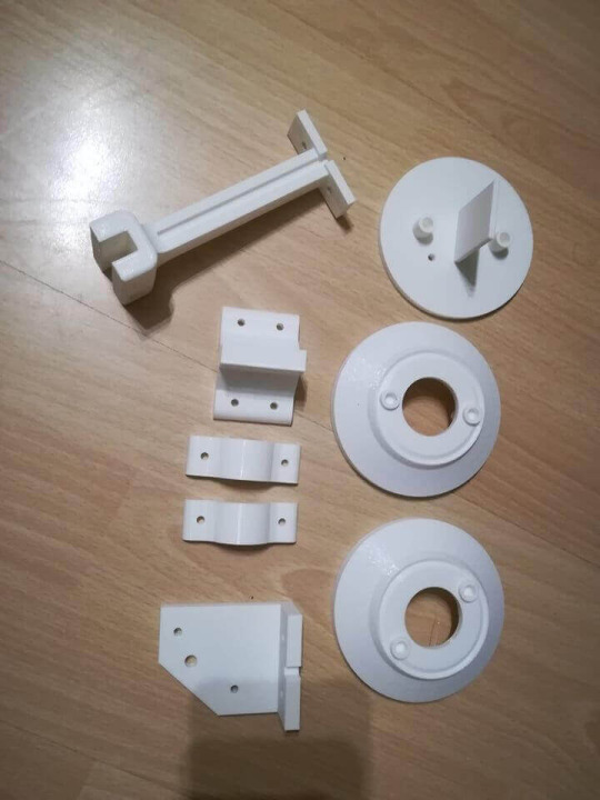
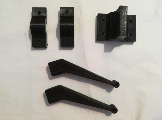
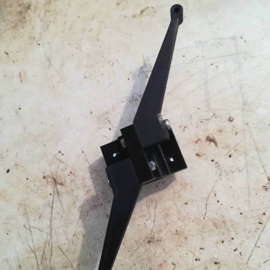
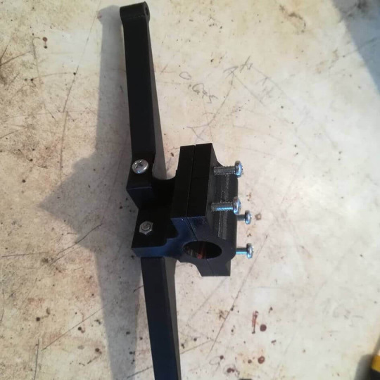
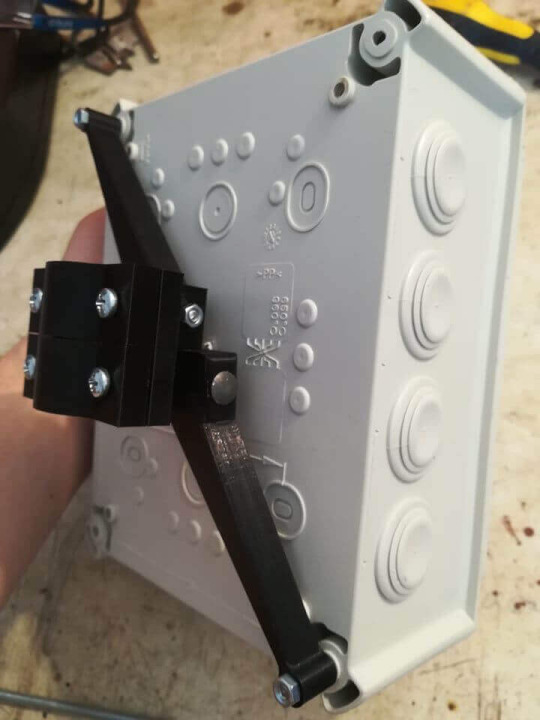
Because I wanted for mounting stand to be easy to assemble and disassemble I needed to make some 3D printed parts. Every part was printed with PLA plastic and designed by me.
Plastic junction box handholder.
If you take a look at my previous instructable you can see that I made handhold with a steel plate which wasnt really practical. So now I decided to make it from 3D printed parts. It is made out of five 3D printed parts which allows quick replace of broken part.
With this holder, plastic junction box can be mounted directly onto the steel pipe. Height of mouting can be optionally.
Temperature and humidity sensor housing.
I needed to designe housing for temperature and humidity sensor. After some reserch on the internet I came up with a conclusion for the final shape of this housing. I designed Stevenson screen with the holder so that everything can be mounted onto the steel pipe.It is made out of 10 parts. The main base with two parts and the "cap" which goes onto the top so that everything is sealed ,so that water cant come in.
Everything was printed with PLA filament.
Step 6: Indoor Data Receiver
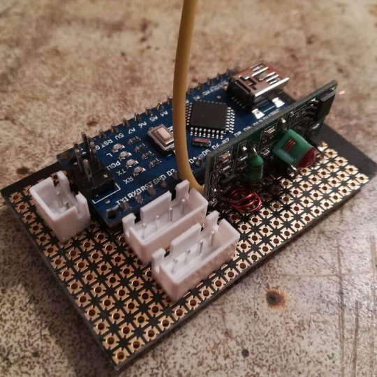
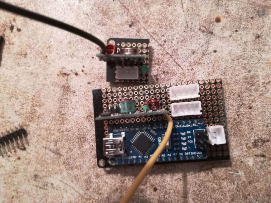
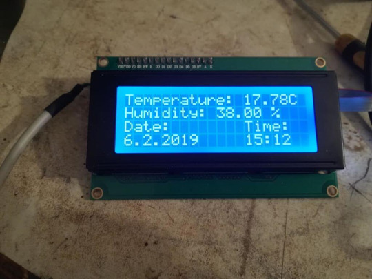
The main upgrade of this project is wireless data transmitting. So for that I also needed to make indoor data receiver.
For that I used 430 MHz receiver for Arduino. I upgraded it with 17cm ( 6.7 inches) antenna. After that I needed to test the range of this module. First test was made indoor so that I saw how the walls affect on the signal range and how this affects on the signal disruptions. Second test was made outside. The range was more than 10m (33 feet) which was more than enough for my indoor receiver.Parts of the receiver:
Arduino Nano
Arduino 430 MHz receiver module
RTC module
LCD display
and some connectors
As it can be seen on the picture, this receiver can display outdoor temperature and humidity, date and time of the day.
Step 7: Testing
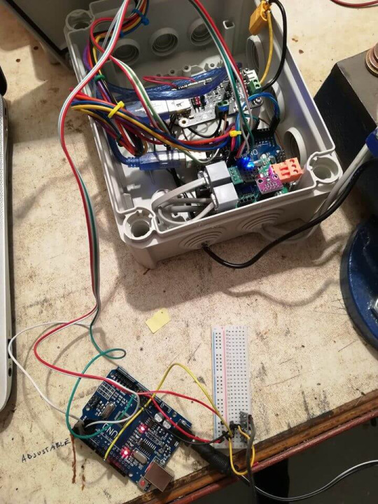
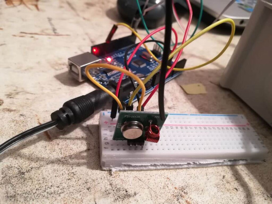
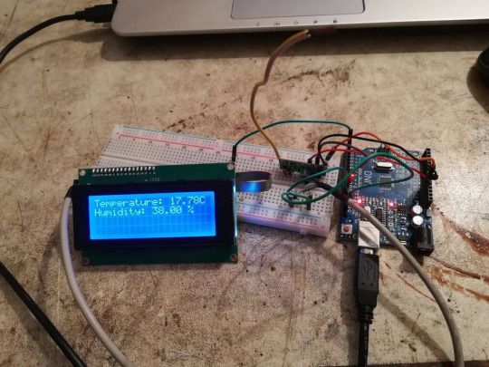
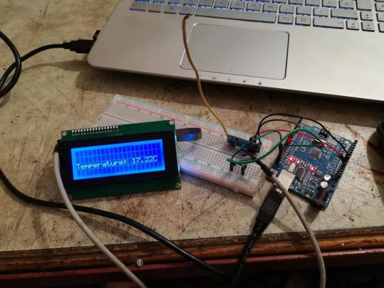
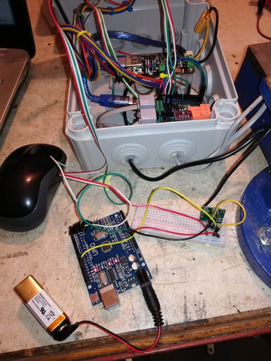
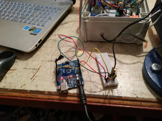
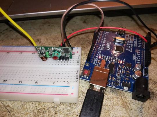
Before I assemble everything together I had to make some tests.At first I had to test transmitting and receiver module for Arduino.
I had to find the proper code and then I had to chage it so it correspond to project demands. First I tried with simple example, i send one word from the transmitter to the receiver. When this was successfully completed, I continued with sending more data.
Then I had to test the range of this two modules. First I tried without the antennas but it didn't have such a long range, about 4 meters (13 feet). Then the antennas were added. After some research I came across some information, so I decided that the length of antenna will be 17cm (6.7 inches). Then I made two test, one indoor and one outside, so that I saw how the different surroundings affects the signal.At the last test transmitter was located outdoor and receiver was located indoor. With this I tested if I can really make indoor receiver. At first there were some problems with the interruptions in the signal, because the received value wasn't the same as transmitted. That was solved with new antenna, I bought "original" antenna for 433 Mhz module on the ebay.This module is good because it is very cheap and easy to use, but it is only useful for small ranges because of the interruptions in the signal.
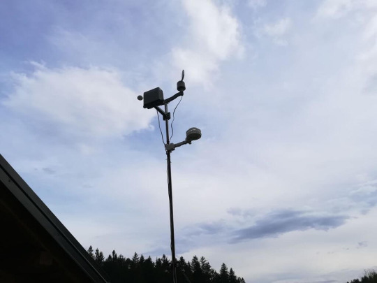
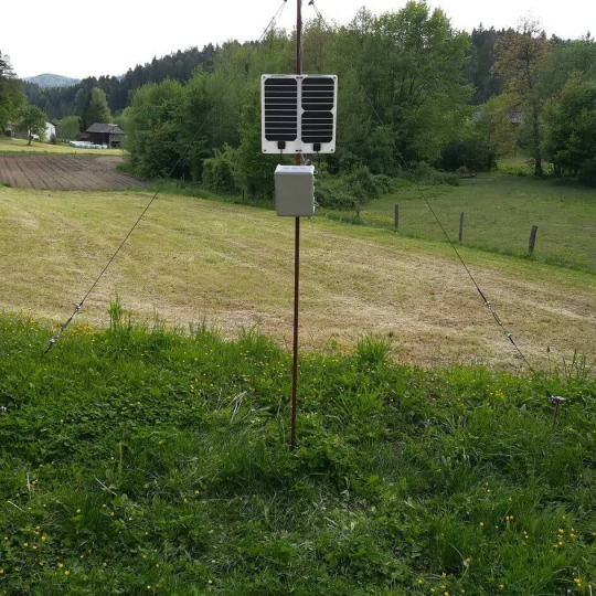
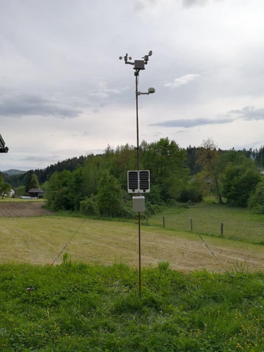
The building of such a project from the idea to the final product can be really fun but also challeching. You need to take time and consider about numerus options for just thing of this project. So if we take this project as a whole you need a lot of time to really make it like you want.
But projects like this are really good opportunity to upgrade your knowledge on the designing and electronics.
It also includes a lot of other technical areas such as 3D modeling,3D printing, welding. So that you dont just get the view of one technical area but you get the glimps how the technical areas intertwine in such projects.
This project is designed in that way that everybody with a basic skills in electronics, welding, griding, designing can make it. But the main ingredient of project like this is time.
0 notes
Text
In this esp32 tutorial we will learn how to remove duplicate elements from an array of integers, using cpplinq. The tests shown on this tutorial were performed using an ESP32 board from DFRobot.
Introduction
In this esp32 tutorial we will learn how to remove duplicate elements from an array of integers, using cpplinq.We will be using the ESP32 as target board and we will also use the Arduino core to program the device.The tests shown on this tutorial were performed using an ESP32 board from DFRobot.
The code
The first thing we will do is including the cpplinq library. This way we will have access to the cpplinq operator that allows to remove duplicate elements from an array.
#include "cpplinq.hpp"
Then we will declare the use of the cpplinq namespace, like we have been doing in the previous tutorials. This way, we don’t need to use the C++ scope resolution operator, making the syntax shorter.
using namespace cpplinq;
In the Arduino setup function, we will start by opening a serial connection. That way, when testing the code, we can check the results on the Arduino
IDE serial monitor.
Serial.begin(115200);
Then we will declare an array of integers with some duplicate values, so we can later remove them.
int ints[] = {1,1,1,2,2,3,4,5,6,7,7,7,7};
As we have been doing in the previous tutorials using cpplinq, the first thing we need to do before applying operators is converting the array to a range object.
from_array(ints)
Then, to remove the duplicate elements from the range, we simply need to use the distinct operator. This operator takes no arguments and will ensure only distinct values will remain on the resulting range.
distinct()
Finally, we will convert the range to a C++ vector, so we can iterate over its elements and confirm that only distinct values remained.The full expression tree can be seen below and it already contains the to_vector operator call, which converts the range into a vector.
auto result = from_array(ints) >> distinct() >> to_vector();
After this we just need to iterate over the vector and print all the elements, so we can check the final values it contains.
for(int i=0; i<result.size(); ++i){ Serial.print(result[i]); Serial.print("|"); }
The final code can be seen below.
#include "cpplinq.hpp" using namespace cpplinq; void setup() { Serial.begin(115200); int ints[] = {1,1,1,2,2,3,4,5,6,7,7,7,7}; auto result = from_array(ints) >> distinct() >> to_vector(); for(int i=0; i<result.size(); ++i){ Serial.print(result[i]); Serial.print("|"); } } void loop() {}
Testing the codeTo test the previous code, simply compile it and upload it to your
ESP32 , using the Arduino IDE.When the procedure finishes, open the IDE serial monitor. You should get an output similar to figure 1. As can be seen, all the duplicate elements were removed from the array, as expected.
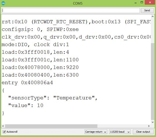
Figure 1 – Output of the program, showing the array without duplicates.
0 notes
Text
ESP32 ArduinoJSON: Printing prettified JSON string
In this ESP32 tutorial we will check how to print a JSON string in a prettified format, which makes it easier for a human to read. The tests shown here were performed using an ESP32 board from DFRobot.
Introduction
In this ESP32 tutorial
we will check how to print a JSON string in a prettified format, which makes it easier for a human to read.
We will be using the ESP32 and the ArduinoJson library.We have already covered in detail on this tutorial how to serialize JSON using the ESP32 and theArduinoJson library.
The code shown here will be very similar, except for the serializing function we will call at the end.So, instead of printing a minified JSON string without spaces and line breaks like we did in the previous post, the function we will call to serialize the JSON document will output a nicely formatted string with some spaces and line breaks.
Naturally, in a final application where we will be sending the JSON using some protocol (HTTP, websockets, etc..), it is more efficient to use the minified version.
Nonetheless, for debugging, it makes it much easier to interpret the JSON string if we use the approach shown on this tutorial.This tutorial targets version 6 of ArduinoJSON. The tests shown here were performed using an ESP32 board
from DFRobot.The codeWe will start by including the ArduinoJson.h library, so all the functionalities we need to serialize the JSON will become available.
#include <ArduinoJson.h>
Moving on to the Arduino setup function, we will start by opening a serial connection. We will later use it to output the JSON string.
Serial.begin(115200);
After that, we are going to declare an object of class StaticJsonDocument. Recall from the
previous tutorial
that this object will hold the memory representation of our object. This memory will be allocated on the stack.We need to specify the capacity of the StaticJsonDocument as a template parameter. The value is specified in bytes. We will use a value of 100, which is enough for our object. For a more accurate estimation, you can use this assistant.
StaticJsonDocument<100> testDocument;
Next we will take care of adding the members of our JSON. We are going to build the following structure, for testing purposes:
{ "sensorType": "temperature", "value": 10 }
To add members to our StaticJsonDocument we will use the [] operator, as shown below:
testDocument["sensorType"] = "Temperature"; testDocument["value"] = 10;
After this, we will need a buffer to hold the serialized string.
char buffer[100];
To obtain the JSON string in a prettified format, we only need to call the serializeJsonPretty function. As first input we pass our document and as second we pass the buffer we have just declared.This function will output the serialized JSON string to the char buffer.
serializeJsonPretty(testDocument, buffer);
After this, we will print to the serial port the prettified JSON string contained in the buffer.
Serial.println(buffer);
The final code can be seen below.
#include <ArduinoJson.h> void setup() { Serial.begin(115200); StaticJsonDocument<100> testDocument; testDocument["sensorType"] = "Temperature"; testDocument["value"] = 10; char buffer[100]; serializeJsonPretty(testDocument, buffer); Serial.println(buffer); } void loop() {}
Testing the codeTo test the code, simply compile it and upload it to your device using the Arduino IDE.
Once the procedure finishes, open the IDE serial monitor tool.You should get an output similar to figure 1. As can be seen, it prints the JSON string in a prettified format that makes it much easier to read.

Figure 1 – Output of the program, showing the prettified JSON string.
0 notes
Text
Micro:bit MicroPython: Getting the status of the buttons
In this microbit tutorial we will check how to interact with the two buttons of the Micro:bit board, using MicroPython.
Introduction
In this microbit tutorial we will check how to interact with the two buttons of the Micro:bit board, using MicroPython.The microbit board has two buttons in the front (button A and button B) which can be used in the development of the application that will run on the Micro:bit[1].
MicroPython offers a very simple to use interface to interact with both these buttons and check if they are/were pressed.
As we will see below, we have available very high level methods, which means we don’t need to worry about handling bouncing effects of the buttons or interrupts.You can check here the documentation for these functionalities.
The code
We will start by importing the microbit module, which will make available the objects we need to interact with the buttons from the Micro:bit board.
import microbit
In this module there are two instances of the Button class that we can use to obtain the status of the buttons. Since the Micro:bit board has two buttons (button A and button B), there are two instances of the Button class representing them (named button_a and button_b, respectively) [2].To check if a button is currently being pressed, we simply need to call the is_pressed
method on the Button instance we want to analyze. This method takes no arguments and returns a Boolean value indicating if the button is currently being pressed.
microbit.button_a.is_pressed() microbit.button_b.is_pressed()
Figure 1 shows all the possible outcomes of calling this method for both buttons.
In the first invocation for button A, the button was not being pressed at the time, which is why it returned the value False.On the second invocation I was already pressing button A, which is why the is_pressed method returned True.Then I’ve done the same for button B. In the first invocation I was not pressing the button, which is why the value False was obtained, and in the second invocation I was pressing the button, which is why the value True was returned.
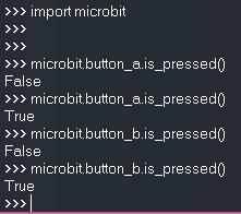
Figure 1– Getting the current status of a button of the Micro:bit
There’s also another very interesting method on the Button class which is the was_pressed.This method takes no arguments and it will return True if the button was pressed since the Micro:bit started or since the last time the method was called.
Otherwise, it will return False [3].When we call this method, the “pressed state” will be cleared. This means that we need to press the button again for the method to return True again [3]. In other words, if we press the button once and we call the was_pressed method twice, only the first invocation will return True and the second one will return False.
microbit.button_a.was_pressed()
Figure 2 illustrates a test to this method.
The first thing I did before sending any command was pressing button A. Then I called the was_pressed method and, as can be seen, it returned True.After that I’ve invoked this method two more times without pressing the button before. Consequently, the method now returned False both times.
This happened because the first invocation cleared the “pressed state”, like we already mentioned.Finally, I’ve clicked button A again and called the method one last time. Then it returned True again, as expected.
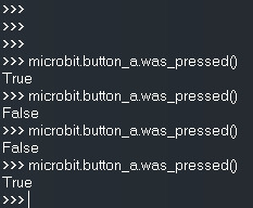
Figure 2– Testing if a button was pressed.To finalize, there’s one additional method mentioned in the documentation that can be useful. This method is called get_presses and it returns the total number of button presses since this method was last called [4]. Like before, a call to the method will reset the counter and next calls without clicking the button will return 0.
microbit.button_b.get_presses()
Figure 3 illustrates an example of calls to this method. The first thing I did was clicking the button 3 times.
Then, I have called theget_presses method, which returned exactly the number 3.After that I called the method again, without pressing the button again.
This time, it returned the value 0.Then I’ve pressed the button 2 more times and called the method afterwards. It returned the value 2, as expected.
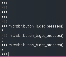
Figure 3– Getting the number of presses on a button.
0 notes
Text
Raspberry Pi 3 Tutorial: Node.js Hello world
In this Rasperry pi tutorial we will check how to get started using Node.js on the Rasperry pi. We will develop a very simple “hello world” application. This tutorial was tested on a Raspberry Pi 3 model B+ .
Introduction
In this raspberry tutorial we will check how to get started using Node.js on theRasperry Pi 3. We will develop a very simple “hello world” application.
This tutorial was tested on a Raspberry Pi 3 model B+, running version 4.9 of Raspbian, installed using NOOBS.
The Node.js version used was 12.2.0. This version is more recent than the one that originally comes installed with Raspbian.Nonetheless, this tutorial should also work for older versions. If you want to update your Node.js version, please follow this guide.
The procedure
The first thing we will do is opening a command line. Once you do it, simply type the following command and press Enter:
node
This should open the Node.js interpreter, where we can send commands. Figure 1 illustrates the expected result after sending the previous command.

Figure 1 – The Node.js interpreter.After this, for printing a “hello world” message, simply write the following command and hit Enter:
console.log("Hello world")
You should get a result similar to figure 2. As can be sen, the “Hello World” message gets printed to the console, as expected.

Figure 2 – Printing a “Hello World” message with Node.js.
0 notes
Text
ESP8266 SPIFFS: Writing a file
In this esp8266 tutorial we will check how to write a file to the SPIFFS file system of the ESP8266, using the Arduino core. The tests shown on this tutorial were performed on a DFRobot’s ESP8266 FireBeetle board.
Introduction
In this tutorial we will check how to write a file to the SPIFFS file system of the
ESP8266, using the Arduino core.For an introductory tutorial on how to mount the SPIFFS file system on the ESP8266, please check here.The tests shown on this tutorial were performed on a DFRobot’s ESP8266 FireBeetle board. The version of the ESP8266 Arduino core used was 2.5.2.
The code
We will start by including the FS.h library, so we can have access to the SPIFFS extern variable, which we will use to interact with the file system.
#include <FS.h>
Then we will move to the Arduino setup function, where we will write the rest of our code. The first thing we will do is opening a serial connection, so we can output the results of our program.
Serial.begin(115200);
After that, we will mount the file system with a call to the begin method on the SPIFFS extern variable. Note that we always need to mount the file system before we start interacting with it.We will also perform an error check to make sure the file system mounted properly before we try to write a file.
if (success) { Serial.println("File system mounted with success"); } else { Serial.println("Error mounting the file system"); return; }
Then we will take care of the creation of the file. To do it, we need to call the
open method o the SPIFFS extern variable.As first input we should pass a string with the absolute path of the file, starting with a forward slash [1].
We will call our file “file.txt“, which means the absolute path should be “/file.txt“.As second input, the open method receives a string representing the file opening mode.
Since we want to write some content to the file, we should use the mode “w“. Note that if the file doesn’t exist beforehand, it will be created [1].
For reference, you can check herethe other available file opening modes.As output, this method returns an object of class File, which we will store in a variable. We will later make use of it to write the content to the file.
File file = SPIFFS.open("/file.txt", "w");
As can be seen here, the File class overloads the C++ Boolean operator. Thus, we can use an IF condition to check if the file was opened with success or some error occured.
if (!file) { Serial.println("Error opening file for writing"); return; }
To write the content to the file, we can call the print method on our File object, passing as input the content we want to write. We will write a very simple testing string.As output, this method will return the number of bytes written to the file. We can use this value for error checking.
Here, for simplicity, we are just assuming that if more than 0 bytes were written, then the procedure was successful. Naturally, this error checking can be improved to check if exactly the same number of characters we expect were written to the file.
int bytesWritten = file.print("TEST SPIFFS"); if (bytesWritten > 0) { Serial.println("File was written"); Serial.println(bytesWritten); } else { Serial.println("File write failed"); }
To finish, we should close the file after all the content is written. We do this with a call to the close method on the SPIFFS variable.
file.close();
The full source code can be seen below.
#include <FS.h> void setup() { Serial.begin(115200); Serial.println(); bool success = SPIFFS.begin(); if (success) { Serial.println("File system mounted with success"); } else { Serial.println("Error mounting the file system"); return; } File file = SPIFFS.open("/file.txt", "w"); if (!file) { Serial.println("Error opening file for writing"); return; } int bytesWritten = file.print("TEST SPIFFS"); if (bytesWritten > 0) { Serial.println("File was written"); Serial.println(bytesWritten); } else { Serial.println("File write failed"); } file.close(); } void loop() {}
Testing the codeTo test the code, simply compile it and upload it to your device using the Arduino IDE. When the procedure finishes, open the Arduino IDE serial monitor.You should get an output similar to figure 1. As can be seen, the file system mounted with success and afterwards the file was written. We can also see that a total of 11 bytes were written to the file, which matches the number of characters of the sentence defined in the code.

Figure 1 – Writing a file to the SPIFFS file system of the ESP8266.
0 notes
Text
ESP8266 Arduino: Mounting the SPIFFS file system
In esp8266 this tutorial we will check how to mount the ESP8266
SPIFFS file system, using the Arduino core. The tests from this tutorial were performed on a DFRobot’s ESP8266 FireBeetle board.
Introduction
In this ESP8266 tutorial we will check how to mount the ESP8266 SPIFFS file system, using the Arduino core.SPIFFS was selected as the file system of the
ESP8266to accommodate the constraints o the device, including the limited RAM [1]. You can read more about the ESP8266 file system here. You can also learn more about SPIFFS here.
In this introductory tutorial we will only check how to mount the SPIFFS file system. Nonetheless, this is a very important procedure since we need to execute it before we use any other SPIFFS file system function [1].The tests from this tutorial were performed on a DFRobot’sESP8266 FireBeetle board. The version of the ESP8266 Arduino core used was 2.5.2.
The code
We will start our code by including the FS.hlibrary. This library will expose the functionalities we need to mount the file system.
#include <FS.h>
After this we can move to the Arduino setup function, where we will write the rest of our code. The first thing we will do is opening a serial connection, so we can output content from our program.
Serial.begin(115200);
After including the FS.h library, like we did at the beginning of our code, we will have access to an extern variable called SPIFFS. We will use this variable to interact with the file system.For this simple example we only want to mount the file system. This is done with a call to thebegin method on the SPIFFS variable.
This method takes no arguments and it will return a Boolean value indicating if the file system was mounted successfully (true) or not (false) [1].Note that this method call will trigger a file system format if it is unable to mount it on the first try [1].We will store the result of this method call in a variable so we can do an error check afterwards.
bool success = SPIFFS.begin();
To finalize, we will check if the mounting procedure occurred successfully, using the variable we have just saved. We will print an informative message to the serial port, indicating the result.
if(success){ Serial.println("File system mounted with success"); }else{ Serial.println("Error mounting the file system"); }
The final complete code can be seen below. The main loop was left empty since, for this introductory example, we just want to test if the mounting procedure executes correctly.
#include <FS.h> void setup() { Serial.begin(115200); bool success = SPIFFS.begin(); if(success){ Serial.println("File system mounted with success"); }else{ Serial.println("Error mounting the file system"); } } void loop() {}
Testing the codeTo test the code, simply compile it and upload it to your ESP8266 device, using the ArduinoIDE.
Once the procedure finishes, open the IDE serial monitor.You should get an output similar to figure 1, which illustrates the success message getting printed.

Figure 1 – Output of the program, showing success on the ESP8266 SPIFFS file system mount procedure.
0 notes
Text
ESP32 cpplinq: The take operator
In this esp32 tutorial we will learn how to use the cpplinq take operator. The tests shown on this tutorial were performed using an ESP32 board
from DFRobot, running the Arduino core.
Introduction
In this tutorial we will learn how to use the cpplinq take operator. This operator allows to create a new sequence from an original one by taking a given number of elements and skipping the remaining.In a concrete use case, if we have for example an array of 10 elements and we pass the value 4 to the take operator, the final array will only have the first 4 elements.The tests shown on this tutorial were performed using an ESP32 board from DFRobot, running the Arduino
core.
The code
As usual, we start by including the cpplinq library, followed by the declaration of the use of the cpplinq namespace.
#include "cpplinq.hpp" using namespace cpplinq;
Moving on to the Arduino setup function, where we will write the rest of our code, we start by opening a serial connection, to be able to output the result of our program.After this we will declare an array with 9 elements, over which we will later apply the take operator.
Serial.begin(115200); int ints[] = {1,2,3,4,5,6,7,8,9};
Then we will proceed to convert the array into a range object, so we can apply the cpplinq operators.
from_array(ints)
Then we will apply the take operator. As already hinted in the introductory section, this operator receives as argument an integer value, specifying how many elements we should take from the original range. The resulting range will contain the elements that we have specified.
For this tutorial we will pass the value 4. This means the 4 first elements of the original range should be taken. These should be the values 1, 2, 3 and 4.
take(4)
After this we just need to convert our range to a
C++ vector
, allowing us to iterate over it and print all the elements.The full chain of operator invocations can be seen below and already contains the call to the to_vector operator, which performs the mentioned conversion to a vector.
auto result = from_array(ints) >> take(4) >> to_vector();
To finish our code, we will iterate over all elements of the vector and print them to the serial port.
for(int i=0; i<result.size(); ++i){ Serial.print(result[i]); Serial.print("|"); }
The final complete code can be seen below.
#include "cpplinq.hpp" using namespace cpplinq; void setup() { Serial.begin(115200); int ints[] = {1,2,3,4,5,6,7,8,9}; auto result = from_array(ints) >> take(4) >> to_vector(); for(int i=0; i<result.size(); ++i){ Serial.print(result[i]); Serial.print("|"); } } void loop() {}
Testing the code
To test the code, simply compile it and upload it to your ESP32 device, using theArduino IDE. Once the procedure finishes, open the serial monitor.You should get an output similar to figure 1. As can be seen, we have obtained a new array that contains only the first 4 elements of the original array, as expected.
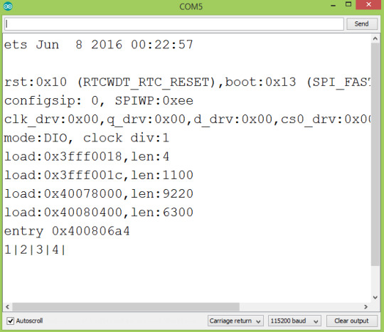
Figure 1 – Result of the program where we applied the take operator to an array.
0 notes
Text
In this esp32 tutorial we will learn how to use the cpplinq skip operator. The tests shown on this tutorial were performed using an ESP32 board from Robot.
Introduction
In this esp32 tutorial we will learn how to use the cpplinq skip operator. This operator will allow us to create a new sequence from an original one, by skipping a predefined number of elements and taking all the others.In other words, if we have an array with 10 elements and we pass the value 2 to the skip operator, the final array will only have the last 8 elements.The tests shown on this tutorial were performed using an ESP32 board from DFRobot, running the Arduino
core.
The code
To get started, as usual, we include the cpplinq library and we declare the using of the cpplinq namespace.
#include "cpplinq.hpp" using namespace cpplinq;
Then, we move on to the Arduino setup, where we will write the rest of the code for our testing use case.The first thing we will do is opening a serial connection, to later output the final results.
Serial.begin(115200);
After that, we will declare an array with 9 elements. This will be the original array on which we will apply the skip operator.
int ints[] = {1,2,3,4,5,6,7,8,9};
Then we will convert our array to a range object, allowing us to apply the cpplinq operators. This is done with a call to the from_array function, as we have done in other previous tutorials.
from_array(ints)
After this we will apply the skip operator. As already mentioned, this operator receives as input the number of elements we want to skip from the original sequence, and it will return a new one with the rest of the non-skipped elements.For testing purposes, we will use the value 4, which means the first 4 elements should not be present in the final result. Looking into the original array, this means the values 1, 2, 3 and 4 should be the ones skipped.
skip(4)
After applying the skip operator, we will convert the resulting range to a C++ vector, so we can iterate it and print all its elements. Below we can see the full chain of operator invocations.
auto result = from_array(ints) >> skip(4) >> to_vector();
To finalize, we will iterate through all the elements of the array and print them to the serial port.
for(int i=0; i<result.size(); ++i){ Serial.print(result[i]); Serial.print("|"); }
The final code can be seen below.
#include "cpplinq.hpp" using namespace cpplinq; void setup() { Serial.begin(115200); int ints[] = {1,2,3,4,5,6,7,8,9}; auto result = from_array(ints) >> skip(4) >> to_vector(); for(int i=0; i<result.size(); ++i){ Serial.print(result[i]); Serial.print("|"); } } void loop() {}
Testing the codeTo test the code, simply compile it and upload it to your
ESP32, using the ArduinoIDE. Once the procedure is finished, open the serial monitor tool.You should get an output similar to figure 1. As can be seen, the first 4 elements from the original array were skipped, as expected.
Figure 1 – Result of applying the cpplinq skip operator to an integer array.
0 notes
Text
A Smart Cup Mat-based on thin film pressure sensor
We all know that drinking more water is good for our health, but it seems that increasing our daily water intake is always easier said than done. We fill up a bottle when we get into the office, then we throw ourselves into work. Few hours later, it still sits there, barely touched, on the left side of our desk. So, I thought why not make a device to remind people to drink water frequently throughout the day. Thus, here comes the idea of smart cup mat! The smart cup mat is mainly based on DFRobot Thin Film Pressure Sensor(SEN0294).
Design Idea: stick the flex sensor on the surface where the cup and the cup mat are in contact with each other. When the sensor detects that the pressure from the cup has been applying to the sensing area for over 1.5 hours, which also means the cup has not been touched in 1.5 hours, the buzzer starts making sound and the LED lights up. If the cup is picked off the cup mat for 3 seconds and above, the smart mat will decide you are drinking water now, and then it will restart timing.
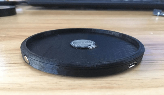
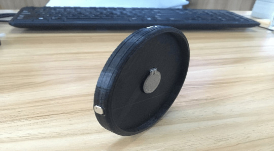
To begin with, I want to introduce this flex pressure sensor. DFRobot is launching 7 new flex sensors with different sensing areas, covering three kinds of shape: circle, square, and long strip. These flex sensors feature great flexibility and easy to use, peel off the protection cover and stick the sensor on the surface you want to detect, then it works.
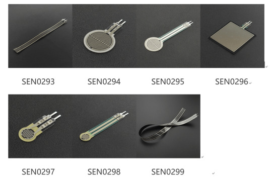
Here, I choose flex sensor of this kind (SEN0294):

Things you may need in the project:

1.RP-C18.3-ST Thin Film Pressure Sensor
2.Beetle - The Smallest Arduino
3.LED ×1
4.10k Resistor ×1
5.6.5*6.5mm smd buzzer ×2
6.20cm Enameled wire
Operation:
Step 1: Build the model with 3D printer.
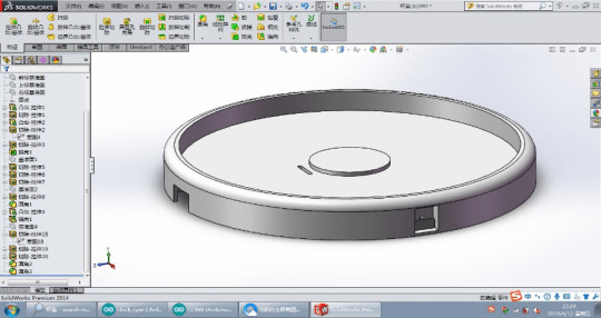
Step 2: Place and solder all parts onto the cup mat.

Step 3: cover the naked wires with Electrical Tape:
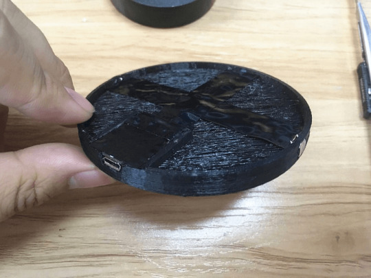
Step 4: burn the programs into beetle controller;
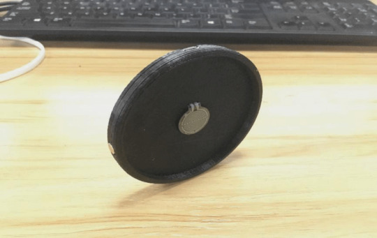
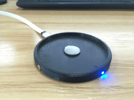
Here is the smart cup mat, give it a try if you like it!
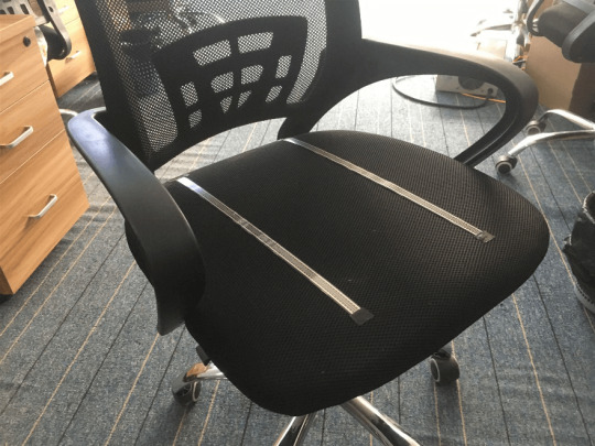
0 notes
Text
ESP32 Arduino cpplinq: The all operator
In this esp32 tutorial we are going to check how to use the cpplinq all operator, using the ESP32 and the Arduino core. The tests shown here were performed using an ESP32 board from DFRobot.
Introduction
In this esp32 tutorial we are going to check how to use the cpplinq all operator, using the ESP32 and the Arduino core.The all operator allows to check if all the elements of an array fill a given condition. It will return true if all the elements fill that condition and false otherwise.The tests shown here were performed using an ESP32 board from DFRobot.
The code
As usual, we will start by importing the cpplinq library and to declare the using of the cpplinq namespace.
#include "cpplinq.hpp" using namespace cpplinq;
We will write the rest of the code in the Arduino setup function. We start by opening a serial connection, to later output the results of our program.
Serial.begin(115200);
Then will declare an array of integers that fills our criteria. So, we should declare an array that has only values lesser than 100.
int array1[] = {5,5,2,89};
Then we will convert the array to a range object, so we can apply the cpplinq operator we need to check if all the elements fill our criteria.The operator we should use is called all. This operator returns true if all the elements of the array respect our criteria, and false otherwise.The criteria is specified as a function, that we pass as input of the all operator. This function will be applied to each element of the array and it should return true if that element fills the criteria, and false otherwise.At the end, the all operator will return true if, for all the elements of the array, the function returned true.For keeping the code compact, we will use the
C++ lambda syntax
to write our function.
all([](int i) {return i < 100;})
The full expression tree can be seen below. Note that, for this array, all elements are lesser than 100. Thus, we expect to obtain the value true.
bool resultArray1 = from_array(array1) >> all([](int i) {return i < 100;});
Now we will apply the same operator but over an array that has some elements that are greater than 100 (thus not respecting our condition). Taking this in consideration, it is expected that the all operator returns the value false.
bool resultArray2 = from_array(array2) >> all([](int i) {return i < 100;});
To finalize the code, we will print the results to the serial port.
Serial.print("Array 1: "); Serial.println(resultArray1); Serial.print("Array 2: "); Serial.println(resultArray2);
The final code can be seen below.
#include "cpplinq.hpp" using namespace cpplinq; void setup() { Serial.begin(115200); int array1[] = {5,5,2,89}; bool resultArray1 = from_array(array1) >> all([](int i) {return i < 100;}); int array2[] = {1,2,200,477}; bool resultArray2 = from_array(array2) >> all([](int i) {return i < 100;}); Serial.print("Array 1: "); Serial.println(resultArray1); Serial.print("Array 2: "); Serial.println(resultArray2); } void loop() {}
Testing the codeTo test, simply compile the previous code and upload it to your
ESP32 device, using the Arduino IDE.After the uploading procedure finishes, open the IDE serial monitor. You should get an output similar to figure 1. For the first array, where all the elements were lesser than 100, the all operator returned the value true. For the second array, since some of the elements did not fill the criteria, the operator returned false.
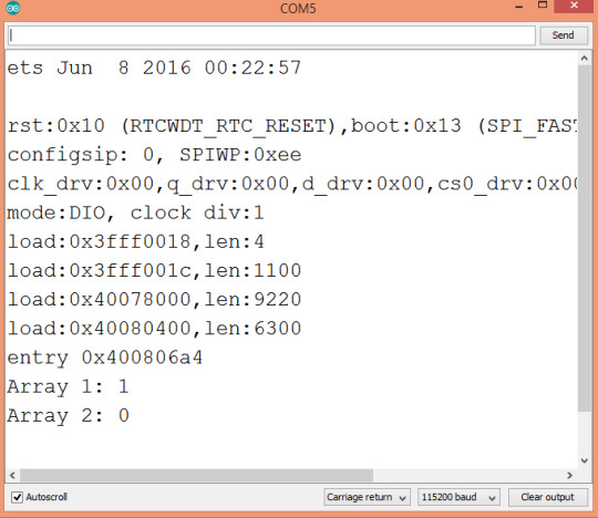
Figure 1 – Output the program.
Related Posts:
ESP32 Arduino cpplinq: Getting started
ESP32 Arduino cpplinq: Filtering an array
ESP32 Arduino cpplinq: min and max operators
ESP32 Arduino cpplinq: The count operator
ESP32 Arduino cpplinq: Concatenating arrays
ESP32 Arduino cpplinq: The Average operator
ESP32 Arduino cpplinq: The Any operator
0 notes
Text
ESP32 Arduino cpplinq: the any operator
In this esp32 tutorial we will check how to obtain the average value of an array, using cpplinq as an Arduinolibrary, running on the ESP32. The tests shown here were performed using an ESP32 board from DFRobot.
Introduction
In this esp32 tutorial we will check how to obtain the average value of an array, using cpplinq as an Arduinolibrary, running on the ESP32.To make the example below slightly more complex, we will chain cpplinq operators to first filter only all the elements of the array that are lesser than 100, and then get the average of those elements.The tests shown here were performed using an
ESP32 board from DFRobot.
The code
The first thing we will do is importing the cpplinq library. After that, we will declare that we will be using the cpplinq namespace.
#include "cpplinq.hpp" using namespace cpplinq;
Moving on to the setup function, we will start by opening a serial connection. We will use it to output the result of our program.
Serial.begin(115200);
Then we will declare an array of integers, which we will first filter and then obtain the average value.
int ints[] = {5,5,2,100,200};
After this, we will need to convert the array to a range object, in order for us to be able to apply the cpplinq operators. We perform this conversion by calling the from_array function, passing as input our array of integers.
from_array(ints)
Then we will filter all the elements of the array that are lesser than 100. To do this, we will leverage the where operator, passing as input a function that implements the filtering criteria.Recall from previous tutorials that this function will be applied to all elements of the array and it should return true if a given element fills the criteria, and false otherwise. So, our function should return true if the integer is lesser than 100, and false if it is greater or equal.Note that we are going to use the C++ lambda syntax.
where([](int i) {return i < 100;})
After this, to get the average of the resulting array of filtered elements, we simply need to call the avg operator, without passing anything as input.
avg()
To chain all the previous function calls, we will use the >> operator. Note that the result of the expression tree should be an integer containing the average value of all the elements lesser than 100.
int result = from_array(ints) >> where([](int i) {return i < 100;}) >> avg();
To finalize, we will print to the serial port the result obtained.
Serial.print("Average: "); Serial.println(result);
The final source code can be seen below.
#include "cpplinq.hpp" using namespace cpplinq; void setup() { Serial.begin(115200); int ints[] = {5,5,2,100,200}; int result = from_array(ints) >> where([](int i) {return i < 100;}) >> avg(); Serial.print("Average: "); Serial.println(result); } void loop() {}
Testing the codeTo test the code, simply compile it and upload it to your device, using the Arduino
IDE. After the procedure finishes, open the serial monitor.You should get a result similar to figure 1. As can be seen, it corresponds to the average of all the elements lesser than 100. Those elements where 5, 5 and 2. We obtained the value 4, which is the average value.
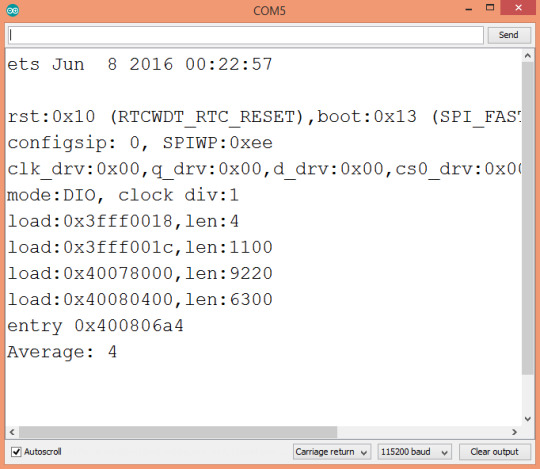
Figure 1 – Output of the program, showing the average value of all the elements of the array lesser than 100.Related Posts
ESP32 Arduino cpplinq: Getting started with the cpplinq library
ESP32 Arduino cpplinq: Filtering an array
ESP32 Arduino cpplinq: Getting minimum and maximum values from array
ESP32 Arduino cpplinq: The count operator
ESP32 Arduino cpplinq: Concatenating arrays
0 notes
Text
ESP32 Arduino cpplinq tutorial: the average operator
In this esp32 tutorial we will check how to obtain the average value of an array, using cpplinq as an Arduino library, running on the ESP32. The tests shown here were performed using an ESP32 board from DFRobot.
Introduction
In this esp32 tutorial we will check how to obtain the average value of an array, using cpplinq as an Arduino library, running on the ESP32.To make the example below slightly more complex, we will chain cpplinq operators to first filter only all the elements of the array that are lesser than 100, and then get the average of those elements.The tests shown here were performed using an
ESP32 board from DFRobot.The codeThe first thing we will do is importing the cpplinq library. After that, we will declare that we will be using the cpplinq namespace.
#include "cpplinq.hpp" using namespace cpplinq;
Moving on to the setup function, we will start by opening a serial connection. We will use it to output the result of our program.
Serial.begin(115200);
Then we will declare an array of integers, which we will first filter and then obtain the average value.
int ints[] = {5,5,2,100,200};
After this, we will need to convert the array to a range object, in order for us to be able to apply the cpplinq operators. We perform this conversion by calling the from_array function, passing as input our array of integers.
from_array(ints)
Then we will filter all the elements of the array that are lesser than 100. To do this, we will leverage the where operator, passing as input a function that implements the filtering criteria.Recall from
previous tutorials
that this function will be applied to all elements of the array and it should return true if a given element fills the criteria, and false otherwise. So, our function should return true if the integer is lesser than 100, and false if it is greater or equal.Note that we are going to use the C++ lambda syntax.
where([](int i) {return i < 100;})
After this, to get the average of the resulting array of filtered elements, we simply need to call the avg operator, without passing anything as input.
avg()
To chain all the previous function calls, we will use the >> operator. Note that the result of the expression tree should be an integer containing the average value of all the elements lesser than 100.
int result = from_array(ints) >> where([](int i) {return i < 100;}) >> avg();
To finalize, we will print to the serial port the result obtained.
Serial.print("Average: "); Serial.println(result);
The final source code can be seen below.
#include "cpplinq.hpp" using namespace cpplinq; void setup() { Serial.begin(115200); int ints[] = {5,5,2,100,200}; int result = from_array(ints) >> where([](int i) {return i < 100;}) >> avg(); Serial.print("Average: "); Serial.println(result); } void loop() {}
Testing the codeTo test the code, simply compile it and upload it to your device, using the
Arduino
IDE. After the procedure finishes, open the serial monitor.You should get a result similar to figure 1. As can be seen, it corresponds to the average of all the elements lesser than 100. Those elements where 5, 5 and 2. We obtained the value 4, which is the average value.
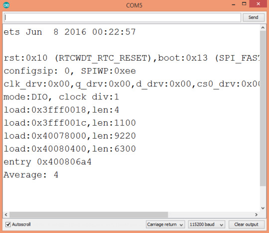
Figure 1 – Output of the program, showing the average value of all the elements of the array lesser than 100.Related Posts
ESP32 Arduino cpplinq: Getting started with the cpplinq library
ESP32 Arduino cpplinq: Filtering an array
ESP32 Arduino cpplinq: Getting minimum and maximum values from array
ESP32 Arduino cpplinq: The count operator
ESP32 Arduino cpplinq: Concatenating arrays
0 notes
Text
ESP32 cpplinq Tutorials: Concatenating arrays
In this esp32 arduino tutorial we will check how to concatenate arrays using cpplinq, running on the ESP32. The tests shown here were performed using an
ESP32 board from DFRobot.
Introduction
In this esp32 tutorial we will check how to concatenate arrays using cpplinq, running on the ESP32.The tests shown here were performed using an ESP32 board from DFRobot.
The code
We will start the code by including the cpplinq library and by declaring the use of the cpplinq namespace.
#include "cpplinq.hpp" using namespace cpplinq;
Then we will move on to the Arduino setup function, where we will start by opening a serial connection, to later output the results of our program.
Serial.begin(115200);
After this we will declare two arrays, so we can append one to the other. These will contain some arbitrary integer values.
int array1[] = {3,4,5}; int array2[] = {1,9,10,22};
Then we will start writing our cpplinq expression tree. The first thing we need to do is converting the first array to a range object, so we can apply the cpplinq operators over it.
from_array(array1)
Then, to concatenate the second array to the first one, we simply need to call the concat operator.This operator receives as input a range object, which will be concatenated to the range over which the operator is being applied. So, we need to convert array2 to a range object and pass is as input of the concat function.
concat(from_array(array2))
Finally, we should convert the resulting range to a type we can iterate. We will convert it to a
vector
. This is done by calling the to_vector operator.
to_vector()
The full expression tree can be seen below. Note that we are leveraging the
auto
keyword, so the compiler infers the type of the returned value.
auto result = from_array(array1) >> concat(from_array(array2)) >> to_vector();
After this, we will iterate the vector and print each value that composes it, to ensure we obtained a result that is the concatenation of both array1 and array2.
for(int i=0; i<result.size(); ++i){ Serial.print(result[i]); Serial.print("|"); }
The final source code can be seen below.
#include "cpplinq.hpp" using namespace cpplinq; void setup() { Serial.begin(115200); int array1[] = {3,4,5}; int array2[] = {1,9,10,22}; auto result = from_array(array1) >> concat(from_array(array2)) >> to_vector(); for(int i=0; i<result.size(); ++i){ Serial.print(result[i]); Serial.print("|"); } } void loop() {}
Testing the codeTo test the code, simply compile it and upload it to your device, using the
Arduino
IDE. Then, open the serial monitor.You should get an output similar to figure 1. As can be seen, the second array was concatenated to the first, as we expected.

Figure 1 – Output of the program, showing both arrays concatenated.Related posts
ESP32 Arduino cpplinq: Getting started
ESP32 Arduino cpplinq: Filtering an array
ESP32 Arduino cpplinq: min and max operators
ESP32 Arduino cpplinq: The count operator
0 notes