#Medium Voltage Cable
Explore tagged Tumblr posts
Visit Tumblr Blog
Explore Tumblr blogs with no restrictions, modern design and the best experience.
Last Seen Tumblr Blogs


acidicghostrose
585 posts

sublimeharmonycherryblossom2
No porn, only men and boy's of legal age , Not only in Belgium
1K posts

Fun Fact
Tumblr Inc. is using 66 technologies for its website.
Text
Medium voltage support insulator manufacturers in India | radiantenterprises
Elevate your electrical solutions with Radiant Enterprises, a top name among customised insulator manufacturers in India. Specializing in high-quality epoxy insulators, we cater to the specific needs of your projects with precision and expertise. As leading medium voltage support insulator manufacturers in India, we provide durable and reliable products that meet the highest industry standards.
Trust Radiant Enterprises for innovative and customized insulator solutions designed to enhance the performance and safety of your electrical systems.
#Epoxy insulator#Customised insulator manufacturers in India#Medium voltage support insulator manufacturers in India#epoxy bushing#epoxy insulator#epoxy resin#electrical company#electrical engineering#electrical industry#fuse cutouts#smart grid sensor#rail insulator#railway technology companies#train operating companies#locomotive#tramways#metro systems#traffic infrastructure#third rail#cable connector#innovative insulators#export quality
4 notes
·
View notes
Text
What is the Purpose of a Screen in MV Cables?
The screen in medium voltage cables plays a crucial role in ensuring safety and performance by containing electric fields, reducing interference, and preventing insulation damage. Dynamic Cables designs high-quality screened MV cables for optimal efficiency and durability in power distribution. Trust our expertise for reliable, long-lasting solutions in industrial and infrastructure applications.

0 notes
Text
Dynamic Cables – High-Quality Medium Voltage Cables for Efficient Power Solutions
Explore Dynamic Cables' range of medium voltage cables, designed to deliver exceptional performance, safety, and longevity. Perfect for industrial, commercial, and infrastructure applications, our cables provide reliable power distribution in even the most challenging conditions. With a focus on innovation and quality, Dynamic Cables is your trusted partner for dependable medium voltage solutions.

0 notes
Text
High-Quality Insulation End Caps up to 36 kV by Yamuna Densons
These Insulation End Caps upto 36 kV from Yamuna Densons help safeguard high-voltage cables from moistures, dust, and destruction. These electrical caps stop any electrical leak, and cables become safe for longer periods. Since they are built from strong insulating materials, they are widely used in power distribution and industries. They install easily and guarantee a tight seal to avoid issues. Whether for factory or utility applications, Yamuna Densons' insulation end caps ensure the reliable performance and safety of up to 36 kV rated cables.
Contact Us Today.

#shrinkable anti tracking#Insulation End Caps upto 36 kV#crimping type center palm lug#gis plug in termination#aluminium lugs for xlpe cable#medium voltage conductor cover#heat shrinkable heavy wall tubing upto 66 kv#epdm cold shrink tube
0 notes
Text
High-Quality Dry Cure CCV Lines Machine for Medium Voltage Cables – Supermac Industries (India) Ltd.
Supermac Industries (India) Ltd. specializes in dry cure CCV lines machine for medium voltage cables, providing advanced solutions for efficient and reliable cable production. Our machines ensure optimal performance, precision, and durability for medium voltage cable manufacturing. Explore our cutting-edge CCV line solutions today!
0 notes
Text
The Importance of Medium Voltage Cable Accessories in GIS Cable Termination
Medium voltage cable accessories play a critical role in gas-insulated switchgear (GIS) cable termination systems, ensuring reliable and efficient operation. This article explores the importance of medium voltage cable accessories in GIS cable termination, highlighting their functions, benefits, and significance in high-voltage applications.
Understanding Medium Voltage Cable Accessories
Medium voltage cable accessories encompass a range of components designed to connect, terminate, and protect medium voltage cables in electrical distribution and transmission systems. These accessories include terminations, joints, connectors, and insulation materials, among others. In GIS cable termination systems, medium voltage cable accessories are specifically designed to interface with the unique requirements of gas-insulated switchgear.
Key Functions of Medium Voltage Cable Accessories in GIS Cable Termination
The importance of medium voltage cable accessories in GIS cable termination stems from their essential functions:
Electrical Insulation: Medium voltage cable accessories provide electrical insulation to ensure the safe and reliable operation of cables within GIS environments. Proper insulation prevents electrical faults, such as short circuits and flashovers, which can lead to equipment damage and service interruptions.
Sealing and Environmental Protection: GIS cable termination accessories seal the cable terminations, protecting them from moisture, dust, and other environmental contaminants. This sealing is crucial for maintaining the integrity of the insulation and preventing corrosion or degradation of cable components.
Mechanical Support: Medium voltage cable accessories offer mechanical support to the cable terminations, preventing stress concentrations and ensuring the long-term stability and durability of the cable system.
Thermal Management: Cable termination accessories facilitate effective thermal management by dissipating heat generated during operation, preventing overheating and maintaining optimal temperature conditions within the GIS enclosure.
Electrical Connectivity: Medium voltage cable accessories ensure reliable electrical connectivity between cables and GIS equipment, minimizing electrical losses and maximizing power transmission efficiency.
Benefits and Significance in High-Voltage Applications
The importance of medium voltage cable accessories in GIS cable termination extends to their numerous benefits and significance in high-voltage applications:
Reliability: Properly selected and installed medium voltage cable accessories enhance the reliability of GIS cable termination systems, reducing the risk of electrical failures and downtime.
Safety: Medium voltage cable accessories provide electrical and environmental protection, enhancing safety for personnel and equipment operating in GIS environments.
Efficiency: Efficient cable terminations and accessories minimize power losses and improve system efficiency, contributing to energy conservation and cost savings.
Compliance: Compliance with industry standards and regulations regarding cable termination and insulation is ensured through the use of approved medium voltage cable accessories, reducing liability and regulatory risks.
Longevity: High-quality medium voltage cable accessories are designed for durability and longevity, minimizing maintenance requirements and extending the service life of GIS cable termination systems.
Conclusion: Ensuring Reliability and Performance in GIS Cable Termination
In conclusion, medium voltage cable accessories play a crucial role in GIS cable termination systems, providing essential functions such as electrical insulation, sealing, mechanical support, thermal management, and electrical connectivity. Their importance lies in their ability to ensure the reliability, safety, efficiency, and longevity of GIS cable termination systems in high-voltage applications. By selecting and installing the right medium voltage cable accessories, electrical utilities and operators can maximize the performance and lifespan of their GIS installations, ensuring uninterrupted power supply and operational excellence.
0 notes
Text
Optical Fiber Power Conductor Manufacturers in India

Power Cable is an electrical cable consisting of one or more electrical conductors, held together with an overall sheath. Power cables are mainly used for power transmission and distribution. Sterlite Power’s Integrated Power Cable manufacturing facility in Haridwar supplies Medium Voltage, High Voltage and Extra High Voltage cables.
Sterlite Power strongly believes in the importance of input quality and process emphasis for superior output. The power cables and Power Conductor are manufactured with the best raw materials in the industry and are approved by major approving bodies and leading consultants. They have been fully type tested as per applicable IS and IEC standards. Further, they are also certified for quality and endurance under several international accreditation programmes including the ‘Dow inside’ Partnership Programme. This consistent quality benchmarking has led major private and public utilities, industries and major EPCs to choose Sterlite Power cables. It is the only Indian company whose products are certified for their quality and endurance by ‘Dow Inside partnership’ programme.
1 note
·
View note
Link
#market research future#medium voltage cables#medium voltage cables types#medium voltage cables company#medium voltage cables industry
0 notes
Text
Comparative Analysis of Top Cable Termination Insulator Manufacturers
In the fast-paced world of electrical engineering, the demand for reliable and efficient cable termination insulators has never been higher. As industries evolve, so does the need for cutting-edge solutions that ensure safety, longevity, and optimal performance. In this blog post, we will take a closer look at Radiant Enterprises, one of the leading cable termination insulator manufacturers in India. We'll explore the nuances that set them apart and delve into the details of their offerings, with a focus on medium voltage cable fittings and customized epoxy termination plugs.

Understanding Cable Termination Insulators
Before we dive into the specifics of Radiant Enterprises, let's establish a foundational understanding of cable termination insulators. These crucial components play a pivotal role in electrical systems, providing insulation and sealing for cables at the point where they connect to various equipment. The right cable termination insulator ensures the prevention of current leakage, protects against environmental factors, and contributes significantly to the overall reliability of the system.
Radiant Enterprises: Setting the Standard
Radiant Enterprises has emerged as a key player in the cable termination insulator manufacturing sector, setting high standards for quality and innovation. Their commitment to excellence is reflected in their range of products designed to meet the diverse needs of medium voltage cable fittings.
Customized Epoxy Termination Plugs
One of the standout features of Radiant Enterprises is their expertise in providing customized epoxy termination plugs. These plugs are tailored to meet the unique requirements of different projects, showcasing a commitment to versatility and adaptability. The ability to customize termination plugs ensures that clients receive solutions that align precisely with their project specifications, a feature that sets Radiant Enterprises apart in a market that demands flexibility.
Medium Voltage Cable Fittings
Radiant Enterprises excels in the manufacturing of medium voltage cable fittings. These fittings are crucial for ensuring optimal performance in electrical systems operating at medium voltage levels. The precision and reliability of Radiant Enterprises' medium voltage cable fittings contribute to the overall efficiency and safety of the systems in which they are employed.
Comparative Analysis
1. Quality and Innovation
Radiant Enterprises leads the industry in terms of quality and innovation. Their continuous investment in research and development keeps them at the forefront of industry trends, offering cutting-edge solutions that consistently exceed customer expectations. The commitment to providing customized solutions, such as epoxy termination plugs, demonstrates Radiant Enterprises' dedication to innovation and client satisfaction.
2. Technological Advancements
Radiant Enterprises stands out for its focus on technological advancements. The incorporation of the latest technological features in their products ensures that clients benefit from state-of-the-art solutions. Radiant Enterprises consistently adopts advanced manufacturing processes and materials, positioning them as a manufacturer at the forefront of technological evolution in cable termination insulators.
3. Tailor-Made Solutions
The ability to provide tailor-made solutions is a key strength of Radiant Enterprises. The customization options available for epoxy termination plugs showcase their commitment to meeting the unique requirements of different projects. This bespoke approach not only sets them apart but also demonstrates a customer-centric focus that is crucial in the competitive landscape of cable termination insulator manufacturing.
Conclusion
In the realm of cable termination insulators, Radiant Enterprises stands as a beacon of quality, innovation, and customer satisfaction. Their expertise in providing customized epoxy termination plugs and their excellence in manufacturing medium voltage cable fittings make them a reliable choice for various projects.
As industries continue to advance, the cable termination insulator market is likely to witness further innovation and the adoption of cutting-edge technologies. Manufacturers that can adapt to these changes while maintaining a focus on quality and customer satisfaction, as exemplified by Radiant Enterprises, will undoubtedly lead the way in this dynamic industry.
#Customized epoxy termination plugs#Medium voltage cable fittings#Cable termination insulator manufacturers in India#Cable termination insulator
6 notes
·
View notes
Text
How to Do a Load Bank Test on a Generator?|EMAX Load Bank
Generators are critical assets for businesses and homes, providing essential backup power during outages. To ensure that a generator will perform as needed during an emergency, it is crucial to conduct regular maintenance and testing. One of the most effective ways to test a generator's performance is through a load bank test. This comprehensive guide will walk you through the steps of performing a load bank test on a generator, ensuring optimal performance and reliability.

What is a Load Bank Test?
A load bank test involves using a device known as a load bank to simulate electrical loads that the generator might encounter during operation. The test ensures the generator can handle its full rated capacity and helps identify any issues that could affect performance. Load bank tests are essential for maintaining the health of standby generators, ensuring they can provide reliable power when needed.

Why Perform a Load Bank Test?
Performing a load bank test has several benefits:
Verification of Performance: Ensures the generator can handle its maximum load without issues.
Identifying Potential Problems: Helps detect issues like wet stacking in diesel generators, which occurs when the engine doesn't reach optimal temperature.
Improved Reliability: Regular testing ensures the generator is reliable and ready for emergencies.
Compliance with Regulations: Some industries require regular load testing to comply with safety and operational regulations.

Types of Load Bank Tests
There are three primary types of load bank tests:
Resistive Load Bank Test: Simulates real-world loads such as lighting and heating. It is the most common type of test.
Reactive Load Bank Test: Simulates loads that include inductive (motors, transformers) and capacitive (capacitors) components.
Combined Load Bank Test: Uses both resistive and reactive loads to simulate the most realistic operating conditions.

Preparation for Load Bank Testing
Before performing a load bank test, follow these preparatory steps:
1. Review Manufacturer Guidelines
Consult the generator’s manual for specific instructions and safety precautions related to load bank testing. Adhering to manufacturer guidelines is crucial to avoid voiding warranties or causing damage.
2. Inspect the Generator
Conduct a thorough visual inspection of the generator. Look for any signs of wear, leaks, or damage. Ensure that the fuel, oil, and coolant levels are adequate and that all connections are secure.
3. Ensure Adequate Ventilation
Load testing generates a significant amount of heat. Ensure that the testing area is well-ventilated to dissipate heat and prevent overheating.
4. Gather Necessary Equipment
Ensure you have the following equipment ready:
Load bank unit
Load cables
Personal protective equipment (PPE)
Monitoring devices (e.g., multimeters, temperature sensors)

Step-by-Step Guide to Performing a Load Bank Test
Step 1: Connect the Load Bank to the Generator
Safety First: Wear appropriate PPE, including gloves and safety glasses.
Shut Down the Generator: Ensure the generator is turned off before making any connections.
Connect Cables: Attach the load bank cables to the generator’s output terminals. Ensure that the connections are secure to prevent arcing or loose connections.
Verify Connections: Double-check all connections to ensure they are tight and correctly aligned.
Step 2: Start the Generator
Start-Up: Follow the standard procedure to start the generator.
Warm-Up Period: Allow the generator to run for a few minutes to reach its normal operating temperature. This helps in accurate load testing.
Step 3: Gradually Apply Load
Incremental Load: Begin by applying a small load incrementally using the load bank. This gradual increase helps prevent sudden surges that could damage the generator.
Monitor Parameters: As you increase the load, continuously monitor the generator’s parameters, such as voltage, current, frequency, and temperature.
Stabilize Each Load Level: Allow the generator to stabilize at each load level for a few minutes. This helps in identifying any potential issues early.
Step 4: Apply Full Load
Full Load Application: Once the generator has stabilized at incremental loads, apply the full rated load. This step is crucial as it tests the generator’s ability to handle its maximum capacity.
Continuous Monitoring: Keep monitoring all critical parameters. Look for any signs of overheating, abnormal vibrations, or unusual noises.
Step 5: Maintain Full Load
Duration: Maintain the full load for a specified duration, typically around 30 minutes to an hour. This duration helps in identifying any long-term issues.
Document Readings: Record all readings and observations during the test. This documentation is valuable for future reference and maintenance planning.
Step 6: Gradually Reduce Load
Incremental Reduction: Gradually reduce the load in small increments until the generator is running without any load.
Cooldown Period: Allow the generator to run without load for a few minutes to cool down gradually.
Step 7: Shut Down and Disconnect
Shutdown Procedure: Follow the standard shutdown procedure for the generator.
Disconnect Cables: Safely disconnect the load bank cables from the generator. Ensure that all connections are secure and the generator is back to its standby mode.

Post-Test Analysis and Maintenance
Review Test Data
Analyze the data collected during the test. Look for any anomalies or deviations from normal operating parameters. Identifying trends or issues early can prevent major problems later.
Inspect Generator
Conduct a post-test inspection of the generator. Look for any signs of stress or damage caused by the load test. Check for leaks, unusual wear, or any other abnormalities.
Perform Necessary Maintenance
Based on the test results and inspection, perform any necessary maintenance. This may include changing filters, topping off fluids, tightening connections, or addressing any identified issues.
Update Maintenance Records
Keep detailed records of the load bank test, including all readings, observations, and maintenance actions taken. This information is crucial for tracking the generator’s performance over time and planning future maintenance.

Safety Considerations
Safety is paramount when performing a load bank test. Here are some key safety considerations:
Follow Manufacturer Guidelines: Always adhere to the generator and load bank manufacturer’s safety instructions.
Use PPE: Wear appropriate personal protective equipment, such as gloves, safety glasses, and hearing protection.
Secure Connections: Ensure all electrical connections are secure and correctly made to prevent electrical hazards.
Monitor Continuously: Never leave the generator unattended during the test. Continuous monitoring is essential to identify and address issues promptly.
Adequate Ventilation: Ensure the testing area is well-ventilated to dissipate heat generated during the test.
Conclusion
A load bank test is an essential part of generator maintenance, ensuring that your generator is capable of handling its full rated capacity and ready to provide reliable backup power during emergencies. By following the steps outlined in this guide, you can perform a load bank test safely and effectively. Regular testing, combined with routine maintenance, will help extend the life of your generator and ensure its reliability when you need it most.
Maintaining detailed records of each load bank test, addressing any identified issues promptly, and adhering to safety protocols will contribute to the long-term performance and reliability of your generator. By investing time and effort into regular load bank testing, you can have peace of mind knowing that your generator is ready to perform at its best when it matters most.
2 notes
·
View notes
Text
Dynamic Medium Voltage Cables: Reliable Power Solutions for Flexible Applications

Dynamic medium voltage cables provide reliable power solutions for flexible and demanding applications. Designed for continuous movement, these cables ensure durability, efficiency, and safety in harsh environments. Ideal for industrial, marine, and renewable energy sectors, they offer superior performance, resistance to mechanical stress, and stable power transmission in dynamic conditions.
0 notes
Text
Tano Cable
Henan Tano Cable Co., Ltd.( TANO CABLE for short), is a leading and professional manufacturer of cable and wire with nearly 30 years manufacturing experience, which is located in Zhengzhou city, Henan province, China.
Bare conductor(AAC, ACSR, AAAC, ACAR), overhead insulated cable, low voltage power cable, medium voltage power cable, high voltage power cable,concentric cable, building wire and so on for power transmission and distribution lines.
Bare conductor
Overhead insulated cable,
PVC insulated power cable
Medium voltage power cable
Rubber cable
Building wire
1 note
·
View note
Text
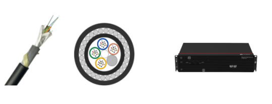
In-Depth Understanding of Fiber Optic Sensing Network
Fiber optic sensing network is a tendency for many applications. It supports a large number of sensors in a single optical fiber with high-speed, high security, and low attenuation. This article provides some information about fiber optic sensing networks.

What is Fiber Optic Sensing Network?
A fiber optic sensing network detects changes in temperature, strain, vibrations, and sound by using the physical properties of light as it travels along an optical fiber. The optical fiber itself is the sensor, resulting in thousands of continuous sensor points along the fiber length.
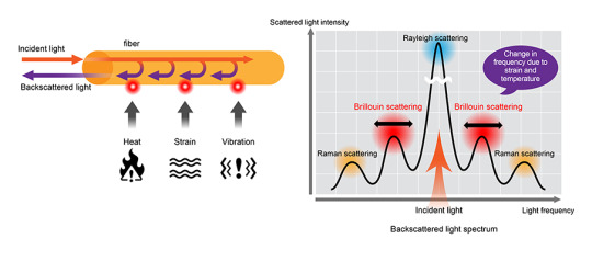
How Does Fiber Optic Sensing Network work?
A fiber optic sensing network works by measuring changes in the backscattered light inside of the fiber when it meets temperature, strain, and vibration.
Rayleigh scattering is produced by fluctuations in the density inside of the fiber. Raman scattering is produced by the interaction with molecular vibration inside the fiber. The intensity of anti-Stokes rays is mainly dependent on temperature. Brillouin scattering is caused by the interaction with sound waves inside the medium. The frequency is dependent on strain and temperature.
Operating Principle of Fiber Optic Sensing Network
Optical Time Domain Reflectometry (OTDR)
In the OTDR principle, a laser pulse is generated from solid-state or semiconductor lasers and is sent into the fiber. The backscattered light is analyzed for temperature monitoring. From the time it takes the backscattered light to return to the detection unit, it is possible to locate the location of the temperature event.
Optical Frequency Domain Reflectometry (OFDR)
The OFDR principle provides information about the local characteristics of temperature. This information is only available when the signal is backscattered in the function of frequency. It allows for efficient use of available bandwidth and enables distributed sensing with a maximum updated rate in the fiber.
Fiber Optic Sensing Network Technologies
Distributed Temperature Sensing (DTS): DTS uses the Raman effect to measure temperature distribution over the length of a fiber optic cable using the fiber itself as the sensing element.
Distributed Acoustic Sensing (DAS): DAS uses Rayleigh scattering in the optical fiber to detect acoustic vibration.
Distributed Strain Sensing (DSS): DSS provides spatially resolved elongation (strain) shapes along an optical fiber by combining multiple sensing cables at different positions in the asset cross-section.
Distributed Strain and Temperature Sensing (DSTS): DSTS uses Brillouin scattering in optical fibers to measure changes in temperature and strain along the length of an optical fiber.
Electricity DTS: Reliable temperature measurement of high-voltage transmission lines is essential to help meet the rising electricity demand. Fiber optic sensing, integrated into distributed temperature sensors on power lines, help ensure optimal safety and performance in both medium- and long-distance systems.
Oil and Gas DTS : Many lands and subsea oil operations rely heavily on DTS for improved safety and functionality in harsh environments. Fiber optic sensing ensures reliable performance and durability in high-temperature, high-pressure, and hydrogen-rich environments.
Oil and Gas DAS: The optical fiber in DAS creates a long sensor element that can detect high-resolution events throughout the entire length of the fiber.
Fiber Optic Navigation Sensing: Fiber optics are used in navigation systems to provide accurate information about location and direction. Aircraft, missiles, unmanned aerial vehicles (UAVs), and ground vehicles require advanced optical fiber navigation technology to ensure reliability and safety.
Fiber Optic Shape Sensing Technology: Reconstructs and displays the entire shape of optical fiber in 2D and 3D. The technology enables cutting-edge applications such as robotic, minimally invasive surgery, energy, virtual Reality (VR), etc.
Wavelength Division Multiplexing (WDM) Technology: Use of Fiber Bragg Gratings (FBGs) with different reflection wavelengths (Bragg wavelengths) in one optical fiber.
Applications
A fiber optic sensing network is used to monitor pipelines, bridges, tunnels, roadways, and railways. Also, it is used in oil & gas, power and utility, safety and security, fire detection, industrial, civil engineering, transportation, military, smart city, minimally invasive surgery, internet of thing (IoT), etc.

Conclusion
A fiber optic sensing network has high bandwidth, security, and stability, is immune to electromagnetic interference, and is lightweight, small in size, and easy to deploy. Sun Telecom specializes in providing one-stop total fiber optic solutions for all fiber optic application industries worldwide. Contact us if any needs.
2 notes
·
View notes
Text
Powering Networks: Medium Voltage Cable Accessories and GIS Cable Termination Insights
In the realm of power distribution, the efficiency and reliability of medium voltage (MV) cable networks are of paramount importance. Within this domain, two critical components stand out: medium voltage cable accessories and Gas Insulated Switchgear (GIS) cable termination techniques. In this article, we delve into the significance of these elements, exploring their roles, advancements, and insights for optimizing power networks.
Understanding Medium Voltage Cable Accessories
Medium voltage cable accessories are essential components that ensure the integrity and performance of MV cable networks. These accessories encompass a range of devices and technologies designed to facilitate cable installation, termination, and protection. From cable joints and terminations to insulation and earthing systems, each accessory plays a vital role in maintaining the reliability and safety of the network.
Advancements in Medium Voltage Cable Accessories
Recent years have witnessed significant advancements in medium voltage cable accessories, driven by the need for enhanced performance, durability, and sustainability. Innovations in materials, manufacturing processes, and design techniques have led to the development of accessories with improved electrical properties, mechanical strength, and environmental resistance.
Key Features and Benefits of Modern MV Cable Accessories
Modern medium voltage cable accessories boast a multitude of features and benefits that contribute to the efficiency and reliability of power networks. These include:
Enhanced insulation materials for improved electrical performance and longevity.
Innovative sealing systems to prevent moisture ingress and environmental degradation.
Integrated monitoring and diagnostics capabilities for proactive maintenance and fault detection.
Modular designs for easy installation, scalability, and flexibility.
Compatibility with renewable energy integration and smart grid technologies.
GIS Cable Termination Insights
Gas Insulated Switchgear (GIS) cable termination techniques are critical for ensuring reliable and efficient power transmission in high-voltage environments. GIS systems offer compact, space-saving solutions for substations and urban areas where space is limited. Cable terminations within GIS systems require specialized techniques and components to maintain electrical integrity and operational efficiency.
Challenges and Solutions in GIS Cable Termination
Despite their advantages, GIS cable terminations present unique challenges related to insulation coordination, thermal management, and installation complexity. Addressing these challenges requires innovative solutions such as:
Advanced insulation materials with high dielectric strength and thermal conductivity.
Precision-engineered termination components to ensure proper alignment and contact pressure.
Thermal management systems to dissipate heat and prevent overheating under high load conditions.
Robust sealing mechanisms to protect against environmental factors and maintain insulation integrity.
Conclusion: Optimizing Power Networks for the Future
In an era of increasing energy demand and environmental awareness, the optimization of power networks is essential for ensuring sustainability and reliability. Medium voltage cable accessories and GIS cable termination techniques play crucial roles in this optimization process, offering innovative solutions to enhance network performance, efficiency, and resilience. By leveraging the latest advancements in these technologies, power utilities and infrastructure developers can build robust, future-proof networks that meet the needs of today and tomorrow.
0 notes
Text
0 notes
Text
MV Onshore Accessories Market Trend Analysis, Latest Revenue Figures, Growth Insights and Forecast to 2030

MV Onshore Accessories MarketGrowth Trend & Forecast with latest research study released by Delvens evaluating the market risk side analysis, highlighting opportunities, and leveraging strategic and tactical decision-making support. The report provides information on market trends and development, growth drivers, technologies, and the changing investment structure of the Global market, the global MV Onshore Accessories Market size is projected to reach a CAGR of 5.9% and Forecast to 2030.
Get Free Sample Report: https://www.delvens.com/get-free-sample/mv-onshore-accessories-market
Manufacturers, suppliers, distributors, and service providers are some of the major market participants. They supply a vast selection of high-quality accessories that are specifically designed to fulfill the needs of onshore applications. To meet changing consumer expectations, these businesses frequently highlight technical improvements, safety features, and energy efficiency in their product offerings.
The medium voltage onshore accessories market is a crucial industry that offers essential parts and services for onshore applications' medium voltage electrical systems. With the ongoing development in demand for dependable and effective power distribution and technological improvements, the market is driven by innovation and competition, guaranteeing the provision of trustworthy and affordable solutions for various onshore industries.
Asia-Pacific to Dominate the Market
The Asia-Pacific region is expected to be the largest region in the MV Onshore Accessories market during the forecast period.
The Asia Pacific area is positioned as a significant market for MV onshore accessories because of nations like China, India, Japan, South Korea, and Southeast Asian states that are leading this expansion.
The prominent players in MV Onshore Accessories Market
ABB Ltd.
Schneider Electric SE
Siemens AG
General Electric Company
Nexans S.A.
Prysmian Group
Eaton Corporation
Legrand SA
Hitachi, Ltd.
TE Connectivity Ltd. and More
Recent Developments
ABB introduced the UniGear Digital switchgear, which incorporates digital technology for enhanced monitoring, control, and maintenance of medium voltage systems.
Schneider Electric launched the Premset Live switchgear, featuring embedded digital capabilities for real-time monitoring, predictive maintenance, and energy management.
Key Findings
The product type segment is further segmented into Cable Joints & Terminations, Switchgear & Circuit Breakers, Transformers, Surge Arrestors, Insulators, and Others. The demand for cable joints and terminations in the MV onshore accessories market is expected to grow steadily.
The voltage rating segment is further fragmented into Home 1 kV to 15 kV, 15 kV to 30 kV to 45 kV, and Above 45 kV. With regard to various voltage ratings, the need for MV onshore accessories differs.
The End-User Industry segment is further segmented into Utilities, Industrial, Commercial and Residential, and Renewable Energy. The renewable energy segment is expected to witness the most growth in the MV onshore accessories market.
Access Full Report: https://www.delvens.com/report/mv-onshore-accessories-market
In addition to the market data for MV Onshore Accessories Market, Delvens offers client-centric reports customized according to the company’s specific demand and requirements.
More Related Reports:
EHV AC and HVDC in XLPE Onshore Land Cables and Accessories Market
Electric Power Transmission and Distribution Equipment market
About Us:
Delvens is a strategic advisory and consulting company headquartered in New Delhi, India. The company holds expertise in providing syndicated research reports, customized research reports and consulting services. Delvens qualitative and quantitative data is highly utilized by each level from niche to major markets, serving more than 1K prominent companies by assuring to provide the information on country, regional and global business environment. We have a database for more than 45 industries in more than 115+ major countries globally.
Delvens database assists the clients by providing in-depth information in crucial business decisions. Delvens offers significant facts and figures across various industries namely Healthcare, IT & Telecom, Chemicals & Materials, Semiconductor & Electronics, Energy, Pharmaceutical, Consumer Goods & Services, Food & Beverages. Our company provides an exhaustive and comprehensive understanding of the business environment.
Contact us:
Unit No. 01, 3rd Floor, Plot No. 56, Block B
Sector 2 Noida, Near Noida Sector 15 Metro Station 201301, IN
+44 20 3290 6466
+0120- 4903958
0 notes