#Si5351
Explore tagged Tumblr posts
Link
Si4732 + Si5351 + STM32F103C8T6 Receptor multimodo https://www.te1.com.br/?p=44922 Por Toni Rodrigues Toni Eletrônica Circuitos...
0 notes
Text
Test odbiornika (z p.cz. na mosfetach) z docelową syntezą Si5351 z BFO g...
youtube
0 notes
Text
Arduino superheterodyne receiver
In this project, we extend the shortwave superheterodyne receiver we developed a few years ago. Like the previous design, this receiver operates on the traditional superheterodyne principle.
In this upgrade, we enhanced the local oscillator with Si5351 clock generator module and Arduino control circuit. Compared to the old design, this new receiver uses an improved version of an intermediate frequency amplifier with 3 I.F transformers.
youtube
In this new design, we divide this receiver into several blocks, which include, mixer with a detector, a local oscillator, and an I.F amplifier. The I.F amplifier builds into one PCB. The filter stage, mixer, and detector stages place in another PCB.
In this prototype build, the Si5351 clock generator drives using an Arduino Uno board. With the given sketch, the user can tune and switch the shortwave meter bands using a rotary encoder. The supplied sketch support clock generation from 5205kHz (tuner frequency : 4750kHz) to 16285kHz (tuner frequency : 15830kHz). If required, this range can further extend or reduce by modifying the Arduino source code. In the given source code, we use Etherkit's Si5351 library to control the clock generator module.

This receiver uses a conventional 455kHz I.F transformer kit in an intermediate frequency amplifier. We use a 2SC724 transistor for each filter stage. The value of this transistor is not critical and can be replaced with any suitable mid-frequency NPN transistor, for example, 2SC930, BF494, BC337, or 2SC829, etc.
The 2nd PCB consists of a filter, mixer, and detector circuit. This mixer stage also uses the NPN low power transistor and can replace with any of the above transistors. The crucial component of the detector phase is the OA90 or 1N34 Germanium diode. It can also change with any suitable Germanium signal diode.
The front filter stage constructs using a pair of ready-made 1µH inductors.

Both I.F amplifier and mixer PCBs design using commonly available through-hole-type components. The I.F transformer used in this circuit base on a standard 455kHz I.F transformer kit. Typically, this kit consists of 42IF101 (yellow), 42IF102 (white), and 42IF103 (black) I.F transformers with capacitors. These days I.F Transformers is a little hard to find. During our search, we found few local stores and online stores that sold above I.F transformer kits. We also noticed some AliExpress and eBay vendors selling the correct 455kHz I.F transformer kits online.
In this prototype, we will use the Si5351 module commonly found in online stores. Generally, this circuit works with any Si5351 module with CLK0 output. The module we used has a built-in I2C level-shifter and voltage regulator, so we connect this module straight to the Arduino Uno 5V supply and I/O terminals.

The suggested supply voltage to this tuner is 6V to 9V. The complete assembly and tuning process of this circuit shows in the video available with this article.
To fine-tune the intermediate frequency amplifier, we feed the known (7MHz) AM signal into the receiver and adjust the I.F transformers.
For testing, we connect this tuner to the external T antenna. During the test, in the morning and evening, we received a good reception on the 41m, 25m, and 19m bands. Although we received frequencies of 16m band and above, it was observed that the sensitivity was slightly low compared to the above meter bands. Due to proximity, we got good reception on several CRI and AIR broadcasts.
All the schematic, KiCAD design files, wiring diagrams, and Arduino sketch files of this project are available on the GitHub repository. All the design files of this project were released under the Creative Commons Attribution 4.0 International license. The Arduino sketch is released under the MIT License.
#tuner#radio#receiver#2SC724#2SC930#2SC829#BF494#BC337#superheterodyne#KiCAD#42IF101#42IF102#42IF103#arduino#Si5351#clock generator#OA90#1N34#Youtube
0 notes
Text
Arduino Becomes Superhet with a Little Help From Friends
A radio receiver is always a fun project. [Jayakody2000lk] decided that his new superheterodyne design would use an Arduino and it looks like it came out very nicely. The system has four boards. An off-the-shelf Arduino, a Si5351 clock generator board (also off-the-shelf), and two custom boards that contain the IF amplifier and mixer.
The receiver started out in 2015 without the Arduino, and there’s a link in the post to that original design. Using the Si5351 and the Arduino replaces the original local oscillator and their have been other improvements, as well. You can see a video about the receiver below.
Tuning is by a rotary encoder and the current software lets you tune from about 4.75 MHz to a little over 15.8 MHz. Of course, you could change to any frequency the Si5351 can handle as long as the mixer and other components can handle it. The IF frequency is the usual 455 kHz.
If you decide to build this yourself, the design files are on GitHub. Overall a very nice and neat design. We are always amazed how little radio architecture has changed since Edwin Armstrong’s day. Of course, we have better components, even if they aren’t meant for radio purposes.
youtube
Arduino Becomes Superhet with a Little Help From Friends was originally published on PlanetArduino
1 note
·
View note
Text
YOTA Croatia 2022 – Day 6
What did you get up to on Day 6? After breakfast we went off to hunt small Si5351 based transmitters around the nearby park. We were able to track down a total of nine transmitters using CW from 80m receivers. Another activity followed shortly after where we got hands-on experience of how to assemble a […] http://dlvr.it/SWVrNT
0 notes
Text
Si5351A Si5351 I2C 25MHZ Controller Clock Generator Board 8KHz To 160MHz 3-5VDC For IDE
Si5351A Si5351 I2C 25MHZ Controller Clock Generator Board 8KHz To 160MHz 3-5VDC For IDE

lastest_volume
0
Just For Today
Click Here To Visit The Shop
N€W Si5351A Si5351 I2C 25MHZ Controller Clock Generator Board 8KHz To 160MHz 3-5VDC For IDE
0 notes
Text
Agilenano - News: The $50 Ham: WSPR-ing Around the World
Everybody has a bucket list, things to be accomplished before the day we eventually wake up on the wrong side of the grass. Many bucket-list items are far more aspirational than realistic; very few of us with “A trip to space” on our lists are going to live to see that fulfilled. And even the more realistic goals, like the trip to Antarctica that’s been on my list for ages, become less and less likely as your life circumstances change — my wife hates the cold. Luckily, instead of going to Antarctica by myself — and really, what fun would that be? — I’ve recently been getting some of the satisfaction of world travel through amateur radio. The last installment of “The $50 Ham” highlighted weak-signal digital modes using WSJT-X; in that article, I mentioned a little about the Weak Signal Propagation Reporter, or WSPR. It’s that mode that let me test what’s possible with very low-power transmissions, and allowed me to virtually visit six continents including Antarctica and Sweden-by-way-of-Alaska. Whispers in the Noise Ask a random amateur radio operator what’s on his or her mind at any given moment and chances are pretty good the answer will be, “How are the bands right now?” That’s shorthand for what the current state of the ionosphere is, which largely determines how well RF signals will bounce off the various layers of charged particles that wrap around the planet. These layers shift and move in diurnal cycles, and undergo longer-term cycles of strengthening and weakening that depend on the cycles of magnetic activity on the Sun. Assessing the state of the ionosphere and finding out which bands have a path to which points on the globe used to be something that hams had to do by spinning the dial and listening for beacon stations. Beacons are stations that transmit a generally low-power signal from a fixed, know location on a regular schedule. If you can hear the beacon, chances are good that you’ve got a propagation path between you and the general area of the beacon on that frequency. While beacons are useful, they have their limits. They depend on the kindness of strangers, who devote resources to running and maintaining the beacon station. Beacons are also subject to occasional maintenance outages, so not hearing a beacon you expect does not necessarily mean that you don’t have a path between two points. But perhaps the most limiting aspect of traditional beacons is that they operate on a pull model — you have to sit down at your radio and intentionally tune into the beacon’s frequency and decode what you hear — beacons almost always use continuous wave (CW) mode with Morse code. Add to that the fact that whatever you learn about the propagation paths available to you stays pretty much within your shack, and beacons have limited utility. WSPR signal by Louis Taber, CC BY-SA 4.0 With those limitations in mind, Joe Taylor (K1JT) began working on a digital mode in 2008 specifically for exploring propagation paths. The protocol was dubbed WSPR, which of course everyone pronounces as “whisper,” which given its capabilities is an apt name indeed. WSPR is a digital mode that employs special digital signal processing algorithms to decode signals with a signal-to-noise ratio (SNR) of -28 dBm in a bandwidth of 2,500 Hz. When transmitting, WSPR sends a compressed 50-bit message that encodes the station’s callsign, the grid location, and the transmitter power. The message is modulated using frequency-shift keying at a very low bit rate — less than 1.5 baud. This means an entire message with error correction takes almost two full minutes to send. Transmissions are synchronized by the WSPR software to begin one second into each even-numbered minute, making accurate time synchronization essential. Propagation Made Visual The shape of things to come — east coast stations are hitting Antarctica on 20 meters, which means I might too in a few hours when the Sun sets over my QTH. As cool as the WSPR protocol is, the magic of WSPR comes from the “R” part of its name: reporting. This is where WSPR closes the loop that traditional beacons leave open, since WSPR client software can be configured to log any WSPR signals received and decoded by a station to a central database. WSPRnet.org is the place where all the reports go; the site contains a searchable database of all “spots” reported as well as a map that shows current contacts by many, many stations. The map on WSPRnet is admittedly a bit janky — it’s based on Google Maps, and an error dialog pops up every time you load a new view. There are other visualizations, though, but even with the issues, WSPRnet’s map is a great way to see what propagation paths may be available to you at the current time. For example, I took a quick peek at the 20-m band just now and found that from my area, I’ve got solid paths to pretty much all of North America. More importantly, I can see that I have no paths into Europe or Asia, and very little to the south into Central and South America. But, by looking at what’s going on with paths on the east coast of the US, where the sun is currently setting and which are actively reaching several stations in and just offshore of Antarctica, I might have a path to the bottom of the planet coming up as the sun sets over me. Doing My Part As I mentioned in my first weak-signals article, I’ve currently got WSJT-X running on a Raspberry Pi 4 that I have dedicated to ham radio use. WSJT-X has a built-in WSPR mode, which makes it easy to switch back and forth between exploring possible propagation paths with WSPR and exploiting that information to make actual QSOs using FT8 or one of the other supported modes. The beauty of using WSJT-X for WSPR work is that it’s basically completely automated. Depending on how you set it up, you can either be a dedicated WSPR receiving and reporting station, or you can choose to also transmit. When I’m going to be in the shack / office, which is almost always, I set up WSJT-X to transmit on WSPR with a 20% duty cycle — that is, one out of every five two-minute blocks will be dedicated to transmitting. That way, I can do my part contributing to the WSPR map — there generally aren’t many WSPR beacons operating in my part of North Idaho, so I figure this is my way of pitching in. Plus, I get the occasional bonus of nabbing a cool contact, like the aforementioned hit on DP0GVN-1, a German research vessel parked off the coast of Antarctica that I reached on the 30-m band using just five watts. Sweden, By Way of Alaska As cool as it is to know you’ve made a solid contact over a path of about 10,000 km on less power than it takes to run an LED light bulb, there’s also a lot to be said for the unusual stations you receive when you leave your WSPR station running. Case in point: the other day I glanced up at WSJT-X and noticed a strange callsign, SA6BSS. After a while of looking at callsigns you get to know which general areas they come from, and I suspected this was a “rare DX” coming from Europe, which is really hard for me to hit with my antenna from the inland Pacific Northwest. A quick lookup on QRZ.com confirmed that SA6BSS is a ham named Mikael Dagman, based in southern Sweden — cool! I quickly spun up the WSPRnet map and was surprised to see that Mikael’s station was reporting its position as coming from Alaska rather than Sweden. I zoomed in the map a little and found that the signal was coming from a grid hundreds of kilometers south of Unalaska Island in the Aleutians. What in the world would a Swedish ham be doing in the North Pacific in February? I shot Mikael a quick email about the contact, and he confirmed that I had indeed received a correct position report from his WSPR station, currently floating around the world on a party balloon! Since he released the balloon on Feb 23, it has traveled at around 11,000 meters altitude from Sweden to the Middle East, across Asia, and over the Pacific to just off the coast of Oregon. There it took a hook and headed back out to sea; as I write this it’s heading roughly in the direction of Hawaii. Literally WSPR-ing around the world — at least halfway so far. SA6BSS launched a balloon carrying a WSPR transmitter on Feb 23 that crossed the Pacific; I copied it when it was south of the Aleutians. Mikael was kind enough to include a little information on the WSPR transmitter he included on his balloon, which is completely solar-powered and weighs in at only 2.6 grams. The spareness of his design is almost comical — it’s just a GPS module, an ATMega328, and an Si5351 for the transmitter. It’s a perfect example of what can be done on a budget, which is right in line with “The $50 Ham” concept. So naturally, building a lightweight, inexpensive WSPR beacon will be the basis of the next installment in this series. #JoeTaylor #WSJT-X #Propagation #The$50Ham #WeakSignal

Agilenano - News from Agilenano from shopsnetwork (4 sites) http://feedproxy.google.com/~r/Agilenano-News/~3/71GKKpe0ScU/the-50-ham-wspr-ing-around-the-world
0 notes
Photo

AURSINC Vector Network Analyzer 50KHz -900MHz HF VHF UHF Antenna Analyzer Measuring S Parameters, Voltage Standing Wave Ratio, Phase, Delay, Smith Chart
https://huntinggearsuperstore.com/product/aursinc-vector-network-analyzer-50khz-900mhz-hf-vhf-uhf-antenna-analyzer-measuring-s-parameters-voltage-standing-wave-ratio-phase-delay-smith-chart/
This is a DIY product that provides perfect vector network measurement capabilities, tiny and handheld, stand-alone with 2.8-inch LCD display, portable with battery powered or USB powered The improved frequency algorithm can use the odd harmonic extension of si5351 to support the measurement frequency up to 900MHz. The 50535-300MHz frequency range of the si5351 direct output provides better than 70dB dynamic, The extended 300M-600MHz band provides better than 60dB of dynamics, and the 600M-900M band is better than 50dB of dynamics The default firmware main function is used for antenna performance measurement. The TX/RX method can measure the complete S11 and S21 parameters. If you need to obtain S12 and S22, you need to manually replace the transceiver port wiring
0 notes
Text
Arduino FT8 bāka
Padalīšos ar mazu projektiņu, ko lietainā naktī, virtuvē uzbūvēju un uzprogrammēju.

Arduino FT8 bāka. Sūta iepriekš ieprogrammētu FT8 signālu ar signāla ģeneratoru (bez WSJT-X, bez datora). Testam iedarbināju pa tiešo no Si5351 signāla ģeneratora (0.06W)

144MHz 2km attālumā cauri visām pilsētas mājām, no websdr.lrg.lv uztvēru un dekodēju. Iespējams sūtīt jebkādu 13 simbolu tekstu.
Notestēju gan 10 gan 2 metros, bet vajadzētu uztīt mazus filtriņus tālākiem testiem, lai nav harmonijas. (Si5351 ģenerators veido kvadrātviļņus diapazonā līdz 200MHz)

Projektam ir potenciāls spēt ģenerēt FT8 ziņas pa tiešo no WSJTX bez radio, pielikot kādu nelielu pastiprinājumu. Tādā veidā FT8 kontaktu iespējams nodibināt ar 15EUR rtl-sdr resīveri un 30EUR transmiteri (arduino, ģenerators, pastiprinājums 1-5W, filtri).
Izmantotie materiāli / literatūra:
Par mikrokontrolieri izmantoju mazu ķīniešu ESP8266 ar iebūvētu OLED displeju - Heltec Wifi Kit 8. (AliExpress) Processora 80 megaherci noder lai FT8 ziņas saģenerētu pietiekoši ātri (salīdzinot ar 8MHz Arduino).
Platītes Adafruit Si5351A Clock Generator klons (AliExpress)
Etherkit Si5351Arduino - biblioteka Si5351 signālģeneratora kontrolei pa i2c.
Etherkit JTEncode - biblioteka FT8 un citu FSK režīmu frekvenču aprēķināšanai.
0 notes
Text
LimeSDRをGQRXで使ってみる
キャンペーンは昨年の4月でした。デリバリは11月予定だったはずなのでちょっと遅れたというところです。
2016/4/29 キャンペーン開始
2016/4/29 さっそくBackする
2016/6/22 ファンディング成功
2016/7/29 コネクタをMicro-Bに変更
2017/1/27 出荷
2017/2/5 受領
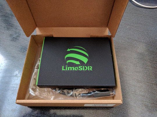
箱は黒いスリーブにレーザカッターでロゴが抜かれて内箱の緑が見えています。添付はUSB micro-Bのケーブルのみです。電源補助用のAプラグが二股になっています。

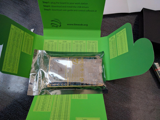
内側には携帯やWiFiなどのバンド番号と周波数(DL/UL)の表が書かれています。地味に有り難いです。
基板は小さく密度は高いです。購入時にUSBコネクタを選べますが、USB micro-Bにしました。他にUSB Aプラグタイプが選択肢にあります。
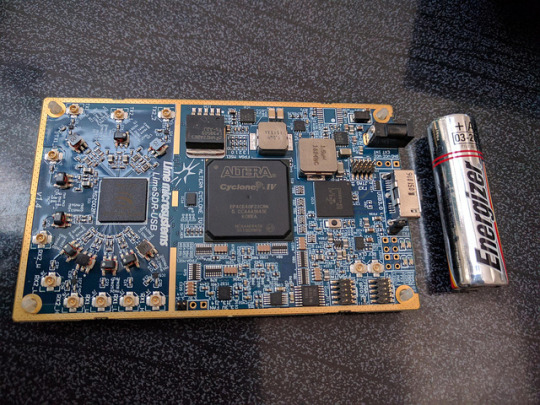

裏面にも部品が詰まっています。プラの6角スタッドが足として付いています。おぉっと思ったのは、おなじみのSi5351が使われています(AではなくC)。
bladeRFとくらべるとかなり小さいです。bladeRFは部品の配置に余裕があり、さらに拡張コネクタも装備されていました(結局使いませんでしたが)。それに対してLimeSDRは部品の密度も高く、拡張コネクタもFPGAから出ている10ピンのGPIOのみです(JTAGと同じコネクタ形状)。
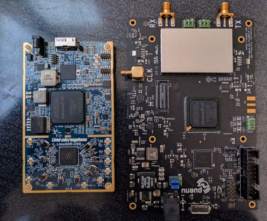
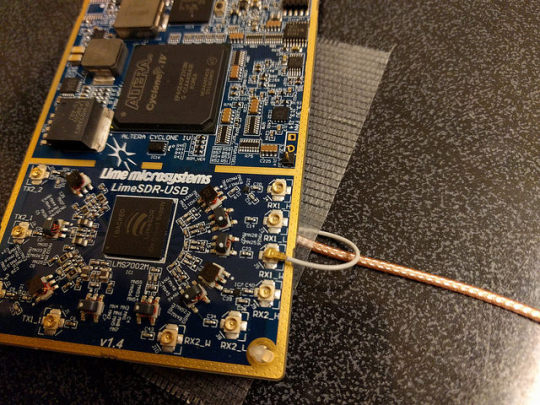
肝心のRFコネクタですが、なんとU.FL(IPX)でごく小さいのです。TX,RXともに2チャネルずつ用意され、さらにTXはチャネル毎に2つ、RXもチャネル毎に3つコネクタが装備されているので、合計2x2+3x2=10個もあります。このようにポート数がとても多いため、SMAではスペースが確保できずU.FLを選択したのだと思われますが、ちょっとやり過ぎの感も否めません。U.FLは機械的強度がとても弱いので、何度も付け外しを繰り返すことができません。早急にケースに入れてケーブルを固定してしまうことが必須だと思われます。今回は仮にUFLのついたケーブルを机にテープで仮止めして外れないようにしています。
ソフトウェアは、例によってmacosにセットアップします。これを機会にようやくsierra(10.12)にバージョンアップしました。
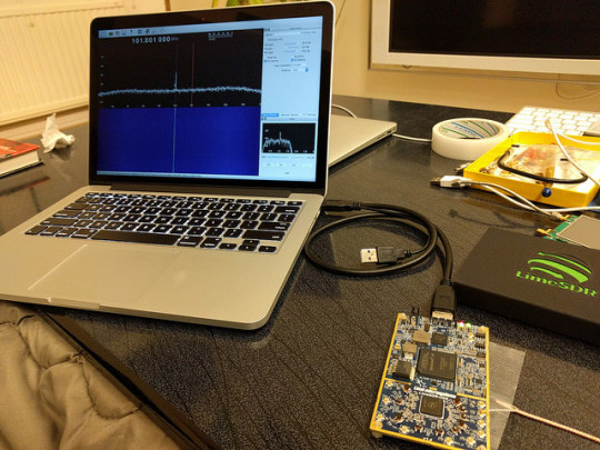
LimeSDR用にLimeSuiteとしてツールがいくつか用意されています。これも公式ページに従ってbrewでインストールしておきます。
$ brew tap pothosware/homebrew-pothos $ brew update $ brew install limesuite
コマンドラインツールのLimeUtilでボードが認識できたら、さっそくファームウェアをアップデートしておきます。
$ LimeUtil -info $ LimeUtil -update
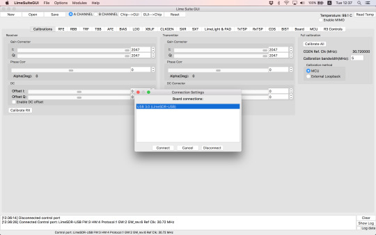
LimeSuiteGUIというグラフィカルツールも用意されています。ボードに載っている各デバイスを細かくコントロールできるようです。動作させるためには、メニューのOptionsからConnection Setupでまずは接続を行う必要があるようです。ちょっとまごつきます。
SDRソフトウェアとしてgqrxをlimesdrで動作させることができるようです。そのためにはソースからビルドする必要があるため、各種ツールキットをインストールします。下記はbrewであっさりとインストール可能です。soapysdrは、SDR関連のライブラリやツールをまとめたSuiteとのことです。
gnuradio
soapysdr
下記はコードからビルド必要でしたが、今回brewのFormulaを用意/アップデートしました。githubに上げてありますので、brew tap ttrftech/gqrxで利用可能です。
gr-iqbal
gr-osmosdr
gqrx
インストールに成功したら、gqrxを起動します。LimeSDRはsoapyというインターフェースで使用する必要があるので、デバイス設定として、
driver=lime,soapy=0
を指定します。起動がうまくいかないことがたまにありますが、もう一度実行するとOKだったりします。Input rateは8000000(8Msps)から55000000(55Msps)程度が指定可能でした。仕様上は上限60Mspsだったはずですが、これを指定すると起動できませんでした。

50Mspsの指定で動作させてみます。RTLドングルに付属していたアンテナをU.FLコネクタに接続します。最初は何も受信できずに焦りました。

設定が2箇所必要でした。まずアンテナポートを選択する必要があります。デフォルトではNONEになっているので何も受かりません。アンテナを接続したポートをプルダウンメニューで選択します。LNAH,LNAL,LNAWがRX1-H,L,Wにそれぞれ対応しているようです。RX2には未対応のようです。
そしてもう一つは、ゲイン設定を上げる必要があります。必須なのはLNAでこれは最大にします。他の設定ではレベルは変化しますが、NFは変化しないようです。適宜設定します。


そうすると受信できるようになりました。この画面では地上デジタルTVの3波がわずかの隙間を空けて並んでいるのが見えています。
ちょっと周波数を上げるとこちらも地デジが1チャネル分の隙間を空けて並んでいます。サンプリングレートが高いので、50MHzの帯域を一度に見ることができます。
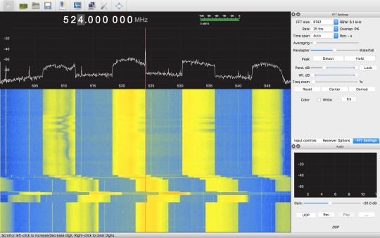
もっと周波数を上げると携帯の周波数が見えてきます。 4つの帯の左からKDDIのLTE, 3G, Docomoの3G,LTEのDL(Down Link)です。
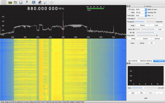
1.5G帯にも携帯の太い帯が見えています。

2.4Gでは室内の通信が見えています。一瞬出る横幅の太い線はWiFi(11gの20MHz幅)。点々と散らばっているのはおそらくBluetoothの周波数ホッピング(FH)です。

とりあえず、受信機として正常に使えているようです。
LimeSDRは0.1〜3800MHzというとても広い帯域に対応していることが謳われていました。気になる低い周波数ですが、300MHz以下を受信可能なことは一応確認しました。しかし顕著に感度は下がって行くようです。特にHF帯ではちょっと実用性は無さそうな感じです。資料を読むと30MHz以下の低い周波数の対応は、チューナではなく信号処理段で特別な処理を行うようですので、もしかすると使い方が足りていないか、まだ対応がされていない可能性もあります。
もう一つ気になることは、300MHz以下ではイメージが顕著に出ることです。例えば180MHzにチューニングすると明らかに地デジの帯が出てきます。右には違う周波数帯の携帯も見えています。チューニングをずらすとばらばらにズレていきます。このチップ(LMS7002)のチューニングスキームを理解できていませんが、300MHz以下の受信をしたい場合には、広帯域信号では不都合があります。適当なLPFで帯域を絞った信号を入れる必要があるようです。
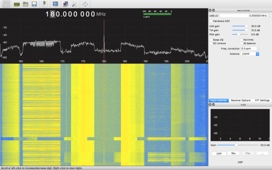
使っているとチューナチップとFPGAどちらも結構発熱します。USBからは7〜800mA消費しているようです。
gqrxでの受信を試してみた印象ですが、300MHz以上の周波数帯では感度も良く、快適に使えそうです。元来WiFiやBluletoothの実験に供することを主眼に設計されているようですので、当然かもしれません。一方、低い周波数での応用は、特に無線用途では難しいと思われます。謳われているスペックを鵜呑みにするとがっかりすることになると思います。
さて、LimeSDRは受信だけでなく、信号生成機能もあります。bladerfではコマンドを使ってデータストリームを送受できたのですが、limesdrでは見当たりません。おそらくgnuradioを使うことで利用できるのではと思うのですが、こちらはまた探ってみたいと思います。
リファレンス
クラウドファンディングサイト CrowdSupplyでのLimeSDRキャンペーン https://www.crowdsupply.com/lime-micro/limesdr
LimeSDR公式 https://wiki.myriadrf.org/LimeSDR
ユーザガイド https://wiki.myriadrf.org/LimeSDR-USB_User_Guide
クイックスタートガイド https://wiki.myriadrf.org/LimeSDR_Quick_Start
LMS7002 Datasheet (wiki) https://wiki.myriadrf.org/LimeMicro:LMS7002M_Datasheet
公式のLimeSuiteインストール手順 https://wiki.myriadrf.org/Lime_Suite#OSX_homebrew
Gqrx http://gqrx.dk/
参考にした先人のgqrx構築手順 https://discourse.myriadrf.org/t/anyone-been-successful-in-getting-limesdr-osx-gqrx-working/657/14
今回作成してみたHomebrewのFormula https://github.com/ttrftech/homebrew-gqrx
3 notes
·
View notes
Text
CircuitPython on Raspberry Pi: UPDATED GUIDES for AMG88XX, IS31FL3731, LSM9DS1, PCA9685, SI5351
CircuitPython on Raspberry Pi: UPDATED GUIDES for AMG88XX, IS31FL3731, LSM9DS1, PCA9685, SI5351
That’s right! It’s CircuitPython on Raspberry Pi! Wire up your favorite sensors and use the same great CircuitPython code you’ve been using with microcontrollers right on your Raspberry Pi!
We’ve got tons of projects, libraries and example code for CircuitPython on microcontrollers, and thanks to the flexibility and power of Python it’s easy to get it working with micro-computers like Raspberry…
View On WordPress
0 notes
Text
An Arduino As A PLL
At the heart of many amateur radio and other projects lies the VFO, or Variable Frequency Oscillator. Decades ago this would have been a free-running LC tuned circuit, then as technology advanced it was replaced by a digital phase-locked-loop frequency synthesiser and most recently a DDS, or Direct Digital Synthesis chip in which the waveform is produced directly by a DAC. The phase-locked loop (PLL) remains a popular choice due to ICs such as the Si5351 but is rarely constructed from individual chips as it once might have been. [fvfilippetti] has revisited this classic circuit by replacing some of its complexity with an Arduino (Spanish language, Google Translate link).
The internals of a PLL frequency synthesiser. Image by Chetvorno – CC0
A PLL is a simple circuit in which one oscillator is locked to another by controlling it with a voltage derived from comparing the phase of the two. Combining a PLL with a set of frequency dividers creates a frequency synthesiser, in which a variable frequency oscillator can be locked to a single frequency crystal with the output frequency set by the division ratios. The classic PLL chip is the CMOS 4046 which would have been combined with a pile of logic chips to make a frequency synthesiser. The Arduino version uses the Arduino’s internal peripherals to take the place of crystal oscillator, dividers, and phase comparator, resulting in an extremely simple physical circuit of little more than an Arduino and a VCO for the 40 metre amateur band. The code can be found on GitLab, should you wish to try for yourself.
It would be interesting to see how good this synthesiser is at maintaining both a steady frequency and minimal phase noise. It’s tempting to think of such things as frequency synthesisers as a done deal, so it’s always welcome to see somebody bringing something new to them. Meanwhile if PLLs are new to you, we have just the introduction for you.
An Arduino As A PLL was originally published on PlanetArduino
0 notes
Photo

Shirt Pocket Transceiver with the Si5351 and OLED http://ift.tt/2iusB2t
0 notes
Text
SDR-YAGI Ver.3のHard評価→GND引き回しに改善の余地あり
SDR-YAGIのVer.3基板と一緒に発注していたドータボード達が届きました。いつも通りなんちゃってリフローで部品を載せて、一発OKで動いてくれました。自分で設計しているので、回路図見なくてもどの部品をどこに載せるか把握できているので楽です(笑)
写真は今回、段数を増やして、かつ小型化したクリスタルフィルタの測定の様子です。測定にはいつもお世話になっているAPB3のネットアナ機能を使っています。負荷容量は設計値からだいぶずらす必要がありましたが、所望の特性に追い込めました。

クリスタルフィルタの特性を測定中

測定系外見
また、前回バージョンの評価時に測定した結果から、クリスタルフィルタの入出力インピーダンスは計算値とぴったり合うことが確認できているので、今回は測定を省こうかとも思いましたが、念のため測定して設計値通りになることを確認しました。下の写真は測定に用いた自作のインピーダンスブリッジです。これとAPB3の組み合わせで測定を実施しました。

自作インピーダンスブリッジ
これらの測定でクリスタルフィルタの特性が把握できたので、プログラムを書き込んでいつも通りラジオを受信してみました。フィルタの切れ味が良くなっていることが音でも実感できました。ちゃんと機能しているようです。
前回の投稿で紹介した、RF Front End基板も一緒に届きました。写真を載せます。まだ何も評価してません(笑)今週末にJA7YAAのOB会があり、宮城に帰る予定なので、それに合わせてこのFront Endボードも組み上げて、大きなアンテナで受信を試したいなぁという希望があります(笑)実はまだラジオ以外は受信したことがないのです。なぜなら...アンテナがないから!!
マンションはアンテナ設置には何かと苦労しそうです。実家のアンテナのありがたみを感じます。

RF Front End基板とRFユニバーサル基板
どうでもいいことですが、今回の投稿から、撮影するカメラをスマホからミラーレス一眼に変更しました。パンケーキレンズで撮ってますが、やはりスマホとは段違いに良く撮れますね!

[GNDの分割方式について(メモ)]
表題のGNDの引き回しについてですが、いろいろと測定やらパターンカットやら試していて細かくは説明しきれないのです。結論としては、今回の回路に関しては「各機能ブロックごとにGNDプレーンを分割して、戻り電流のルートを明確にする」ことが最善と判断しました。今まではアナログGNDとデジタルGNDの二系統構成でしたが、この構成ではLO信号によってGNDが揺れていることが観測されました。この辺のGND処理方法は基板や回路ごとに対応する必要があり、なかなか予想しにくい領域ですね。これがソフトな時代に生きるハード屋さんの存在価値でもあると思います。
あとは、このLOノイズを退治すれば、目的信号のみのクリーンな送信信号が得られます。もっとも、現時点でもRF Front End基板に載せる送信LPFで十分退治可能なレベルにはなっていますが。オンエアも近づいてきてますね!
早くUI実装しよっと。いつも後回しになっちゃう(笑)
0 notes
Text
10kHz to 225MHz VFO/RF Generator with Si5351 - Version 2 - Arduino Project Hub
0 notes